_GOTOBOTTOM
Dioramas
Do you love dioramas & vignettes? We sure do.
NEWS
Russian Railway Switch by Armor35
JPTRR
Staff MemberManaging Editor
RAILROAD MODELING
#051
Visit this Community
Tennessee, United States
Joined: December 21, 2002
KitMaker: 7,772 posts
Armorama: 2,447 posts
Posted: Friday, February 22, 2013 - 05:49 AM UTC
Armor35 announces a switch in subjects with this 1/35 rail trackwork switch!

Link to Item

If you have comments or questions please post them here.

Thanks!
velotrain
Visit this Community
Massachusetts, United States
Joined: December 23, 2010
KitMaker: 384 posts
Armorama: 320 posts
Posted: Friday, February 22, 2013 - 07:26 AM UTC
Hi Fred -

Make that 5' gauge, or 4.98688' based on the Google conversion.

> they are preparing a Soviet 6-foot gauge (1520 mm) switch

For anyone who wants some historical background, see:

http://en.wikipedia.org/wiki/Standard_gauge

There is still a fair amount of meter gauge in Europe and a lot elsewhere. There were also 500mm and 600mm feldbahn lines in much of Europe, mostly for short runs in aggregate (clay, peat, sand, gravel) transort or industrial usage, and some two-foot lines in the US - most notably the "Maine two-footers", which all closed down during the Depression, but you can still see (and ride) the original equipment along the Portland, ME waterfront - www.mainenarrowgauge.org/
Two foot and close (1' 11.5") lines were also used a lot across the UK, particularly in the slate quarries of Wales. In the past few years the Welsh Highland Railway has been rebuilt - completed, and they run some unusual and impressive 2' gauge Garratt steam engines brought in from South Africa.


They also built some huge ones in S.A. at a wider gauge, and one has been restored in Australia - video here: http://www.youtube.com/watch?v=aPNSWBGTffk
If anyone runs live steam in their garden, I foolishly bought a 1:20 version a few years back - PM for info.

Charles
JPTRR
Staff MemberManaging Editor
RAILROAD MODELING
#051
Visit this Community
Tennessee, United States
Joined: December 21, 2002
KitMaker: 7,772 posts
Armorama: 2,447 posts
Posted: Friday, February 22, 2013 - 04:49 PM UTC

Quoted Text

Make that 5' gauge, or 4.98688' based on the Google conversion.


Charles - thanks! How'd I mess that up? At least I correctly stated 5' gauge in other reviews!
velotrain
Visit this Community
Massachusetts, United States
Joined: December 23, 2010
KitMaker: 384 posts
Armorama: 320 posts
Posted: Monday, February 25, 2013 - 04:28 AM UTC
I’m a bit surprised that this is being marketed as a switch, when in reality it only comprises perhaps 15% of what a railroad considers a switch. Although the section shown is very handsomely reproduced with excellent detail, I have to wonder just how many modelers will choose to use this fragment of a switch in a diorama, as I’m uncertain as to just what it adds by itself – other than confusion. No doubt the main reasons for this situation are the dioramatist’s limited space and Armor35’s design and production costs. I suspect that at some future point they will release the missing components – for those modelers who are willing to allocate the space for it.

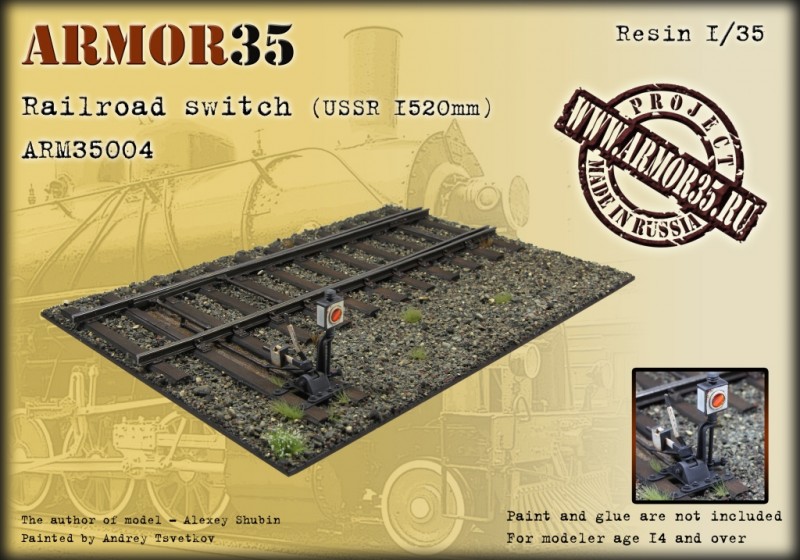
I tried to find the dimensions of this component, but Armor35 doesn’t yet list this product on their website. I would guess that the additional required segments would bring the total length out to about 36”, but that depends largely on what “number” they are assigning to this switch, which has to do with the radius of the diverging track just beyond the point of the “frog”.


This number is the ratio of a measurement taken at any point between the frog point rails, and how many multiples of that measurement this location lies from the point of the frog. Industrial sidings have a very low switch number (~6-8), as a freight train switching them will be moving quite slowly. However, switches for a high-speed passing track on a main line will be a much higher number (~20-30). The main line is always that route taken by the straight track, on the basis of it carrying the higher speed traffic. The guard rails across from the frog ensure that the outer wheel (of each axle) is pressed firmly against the stock (outer) rail, so that the inner wheel has no opportunity to jump to the other track while passing through the frog. This system is not foolproof, and sometimes a car will have one truck (2 axles) follow one track, while the second truck goes the other way, which is known as “splitting the switch” – invariably leading to that car derailing and an accident; the degree of which depending on many factors.

Much research has led to improvements in switches, greatly improving safety in allowing express trains to pass through switches at a much higher speed - even if taking the divergent track. Part of the need for this is the increased instance of “single track mains”, where trains traveling at varying speeds in opposite directions need to quickly duck into a siding to let a priority train pass by, but then quickly resume their own journey. There are many special situations requiring specialized types of switches, and information on these can be found on the web.


This model switch (properly termed a “turnout”, to distinguish it from the many electronic switches on a model railroad) illustrates a “dual-gauge switch”. The “standard gauge” only goes straight through this switch, while the “narrow gauge” can either turn left (approaching from the left), or also continue straight. I won’t hazard a guess as to why the points are currently set in this way, as for the time being no train of either gauge can (safely) pass through this switch. It’s simply a matter of following the lines of the rails, and at the moment the points do not connect with either the narrow or standard gauge stock rails.

Although many of you are possibly overwhelmed at this point [sic], this is merely the visible tip of the iceberg as far as switch technology goes. The isolated switch in this kit is manually operated at the switchstand (usually kept locked against vandalism), but in complex junction areas all the switches are controlled in a centralized location to facilitate communication and coordination. In modern times electronic “switch motors” are remotely controlled from perhaps hundreds of miles away, while formally the “Armstrong” method of throwing a lever in a local interlocking tower would transmit the mechanical motion to the switch “throwbar” by an elaborate connecting system of rods and levers, as partially illustrated here by the restored “signal frame” of St. Albans South in England. We will leave the color codes for another time.


pzturm
Visit this Community
Sør-Trøndelag, Norway
Joined: February 03, 2013
KitMaker: 10 posts
Armorama: 9 posts
Posted: Monday, February 25, 2013 - 05:48 AM UTC
velotrain: thanks for an informative reply.
A little off topic, but what are the "clocks" on the shelf inside the interlocking tower?

Regards
srmalloy
Visit this Community
United States
Joined: April 15, 2012
KitMaker: 336 posts
Armorama: 298 posts
Posted: Monday, February 25, 2013 - 07:41 AM UTC

Quoted Text


This model switch (properly termed a “turnout”, to distinguish it from the many electronic switches on a model railroad) illustrates a “dual-gauge switch”. The “standard gauge” only goes straight through this switch, while the “narrow gauge” can either turn left (approaching from the left), or also continue straight. I won’t hazard a guess as to why the points are currently set in this way, as for the time being no train of either gauge can (safely) pass through this switch. It’s simply a matter of following the lines of the rails, and at the moment the points do not connect with either the narrow or standard gauge stock rails.


Actually, a train can safely go through the switch from right to left on any of the track routes; this is a 'trailing' move, since the points are facing away from the rolling stock for such a move, and the wheels will push the points into the correct position for the movement in that case (as opposed to a move from left to right, a 'facing' move, where the switch points would have to be definitively thrown in one direction or the other).

The switch is sitting that way because it's in a neutral position, being unconnected to anything. In a prototype switch, the points are actually bent into position when the switch is thrown, and the 'neutral' position of the points has neither point in contact with the rails (this increases the gap between the rail and the other point when the switch is thrown to prevent a wheelset from catching the wrong point if it's gauged wrong). The points would be connected to each other by one or two throw bars, one of which would extend out -- generally on the straight side of the switch -- to the throw mechanism, which moves ('throws') the points to one limit or the other and applies extra pressure to hold the points in position until the throw mechanism is reset. The throw mechanism incorporates a mechanical advantage to reduce the effort to throw the switch (the points in a main line turnout can weigh up to 1200 pounds, so you can see why switchmen had to be strong before mechanical throw linkages were replaced with electrically-driven throw mechanisms).
velotrain
Visit this Community
Massachusetts, United States
Joined: December 23, 2010
KitMaker: 384 posts
Armorama: 320 posts
Posted: Monday, February 25, 2013 - 10:51 AM UTC
Sean -

Given the weight of the points that you mention, is it guaranteed that the train will throw them? Particularly on the NG side, where the train would have less weight/mass. I know that modelers will have sprung switches for automated reversing loops, routing, etc, but I don't believe they do that on the proto.

Charles
velotrain
Visit this Community
Massachusetts, United States
Joined: December 23, 2010
KitMaker: 384 posts
Armorama: 320 posts
Posted: Monday, February 25, 2013 - 11:45 AM UTC

Quoted Text

velotrain: thanks for an informative reply.
A little off topic, but what are the "clocks" on the shelf inside the interlocking tower?

Regards


Clemens -

That isn't really OT, but I don't know. The British are very good at writing things up, so I suspect it wouldn't be that hard to find. Maybe try using "railway signalbox".

Charles
JPTRR
Staff MemberManaging Editor
RAILROAD MODELING
#051
Visit this Community
Tennessee, United States
Joined: December 21, 2002
KitMaker: 7,772 posts
Armorama: 2,447 posts
Posted: Thursday, February 28, 2013 - 12:37 PM UTC

Quoted Text

A little off topic, but what are the "clocks" on the shelf inside the interlocking tower?


This is from my UK RR SME (Subject Matter Expert):
Hi Fred,

Those clocks are the faces of machines called 'Block Instruments'. In very, very simple terms the needle on the clock points to a series of sectors that show whether a line is clear or not and thus whether the signalman can accept the offer of a train from the next interlocking tower (signalbox in UK English).

British railway signalling is an immensely complex subject thanks to the density of the network and its services and also, the British obsession with railway safety. That all started when Stephenson's Rocket ran down and killed one of the most important politicians in the land on day 1 of the UK's first inter-city railway in 1830. I'm not much of an SME on signalling so it's far better for me to point you towards a few links. See here...

http://www.railsigns.co.uk/info/ablock1/ablock1.html

http://en.wikipedia.org/wiki/British_absolute_block_signalling

http://www.railway-technical.com/sigtxt1.shtml

and best of all probably...

http://www.signalbox.org/block.shtml

The colour codes on the levers are standard across the UK and here's a list of what they mean...

http://modratec.com/mud_lev01.php

Saint Alban's signal box is rather a small example as it was at the end of a not very busy branch line (short line). Many signal boxes had over 100 levers and the largest survivor has 180. Mechanical signalling like this is now rare in the UK and limited to a few small geographic areas. Typically, I don't think there is any mechanical signalling left in London now.

I hope this helps.

All the best

Ian
pzturm
Visit this Community
Sør-Trøndelag, Norway
Joined: February 03, 2013
KitMaker: 10 posts
Armorama: 9 posts
Posted: Friday, March 01, 2013 - 04:16 AM UTC
Thanks for your reply. Very informative links there!
Many of my questions where answered.
srmalloy
Visit this Community
United States
Joined: April 15, 2012
KitMaker: 336 posts
Armorama: 298 posts
Posted: Friday, March 01, 2013 - 09:30 AM UTC

Quoted Text

Given the weight of the points that you mention, is it guaranteed that the train will throw them? Particularly on the NG side, where the train would have less weight/mass. I know that modelers will have sprung switches for automated reversing loops, routing, etc, but I don't believe they do that on the proto.


Narrow-gauge track will have lighter rails. Having watched it happening in proto, I know that it works for standard-gauge; it's also deprecated, first because it slams the switch mechanism around, and second because for the kind of low-traffic areas where there wouldn't be a dedicated switchman, it is common practice to lock the switch mechanism so that it can't be thrown (to keep someone from maliciously throwing the switch to unexpectedly redirect cars or accidentally leaving it set wrong), and rolling stock that tries to push through a switch where the throw mechanism has a lock keeping it from moving will derail the truck.
velotrain
Visit this Community
Massachusetts, United States
Joined: December 23, 2010
KitMaker: 384 posts
Armorama: 320 posts
Posted: Friday, March 01, 2013 - 11:10 PM UTC

Quoted Text

and rolling stock that tries to push through a switch where the throw mechanism has a lock keeping it from moving will derail the truck.


Actually, they don't want that to happen anywhere near the switch, as the car would almost certainly foul the switch, blocking the other track - which could be a mainline.


Not totally on topic, but I love this photo.
My caption is, "No, I go first".

 _GOTOTOP