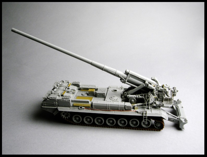
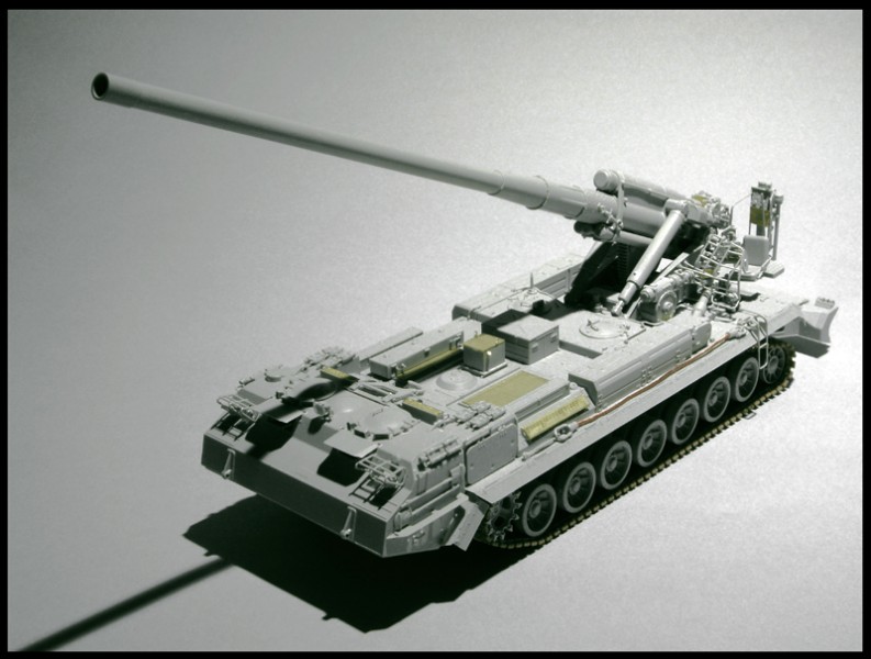
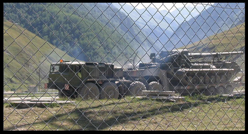
The 2S7 Pion (Peony most Self-Propelled guns are named after trees or flowers, not unlike America's "Peace Keeper" missiles :-) , is a huge weapon and has the longest range of fire compared with any other modern field artillery unit. It is also the largest self-propelled artillery gun in the world . While it is only partially armored and weighs 50.7tons/46-mt, it is 43' 3/12.8 ~13.20-meters long (the hull is 10.5 meters alone), 11' 1 /3.5~3.38-meters wide and 9' 10/3~3.5 meters high. That roughly translates into 366mm x 100 mm x 100 mm in 1/35 scale, the 2A44 itself is huge barrel length is 11240 mm (321 mm in scale).
The design of the 2S7 gained momentum in response to The 6 Day War of 1967 to counter the success that the Israelis were having using their American made 175-mm M107s in the counter battery fire versus the Egyptian forces in the fight over the Suez Canal. New objectives were, to build a gun that would be able to outrange the enemy artillery and engage them with both conventional, as well as the nuclear and chemical rounds. The new weapon, dubbed Article 216, while under preliminary development by the end of 1967, was developed in two different directions:
Article 216sp1 used components of the T-10 heavy tank and a V-2-type diesel engine;
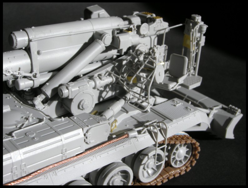
Article 216sp2 used the driveline of the T-72 tank but with the running gear of the T-80 series tanks (individual, torsion with stopping hydro absorbers); though with 7 road wheel stations and six track-return rollers (that support the inside of the track only) for the longer hull. Chief designer was N. S. Popov, who was the head of KB-3, the descendent of the Kotin design bureau in Leningrad, and who was also developing the T-80 series tanks at the same time.
Both variants were combined with the massive 2A44 203mm gun, designed by the famous "Barrikady" factory in Volgograd (Stalingrad.) The later variant, Article 216sp2, won out and was fully developed with it's V-46-1, the V-type 12-cylinder diesel engine completed with turbocharger; reaching a maximum power of 750 hp. The official designation SO-203(2S7) is its GRAU designation. It was identified for the first time in 1975 in the Soviet army and so was called M-1975 by NATO (the 2S4 Tyulpan also received the M-1975 designation). One brigade of 72 of these guns became part of the 34th Artillery Division in GSFG during the late 70's. Later, this chassis was used to develop and improve a number of other heavy vehicles.
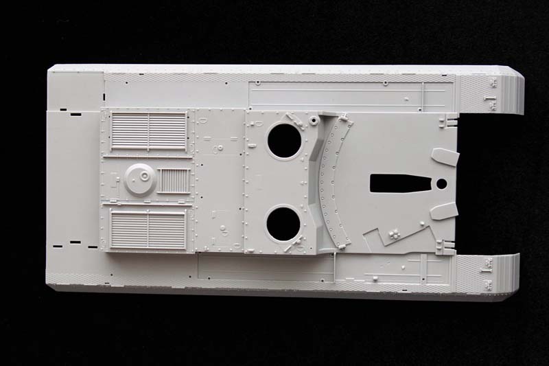
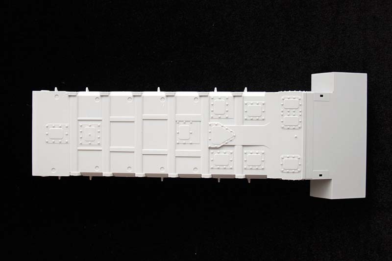
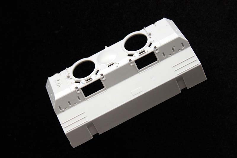
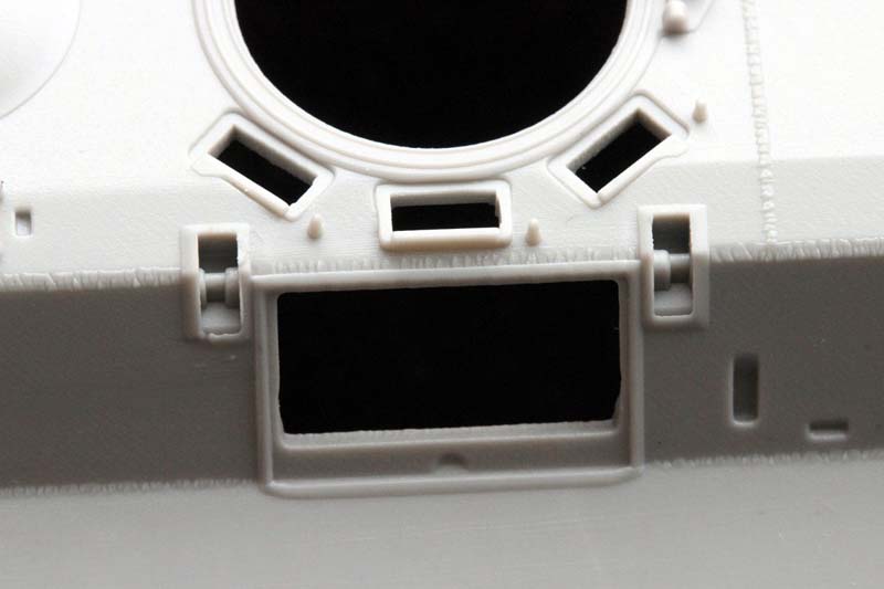
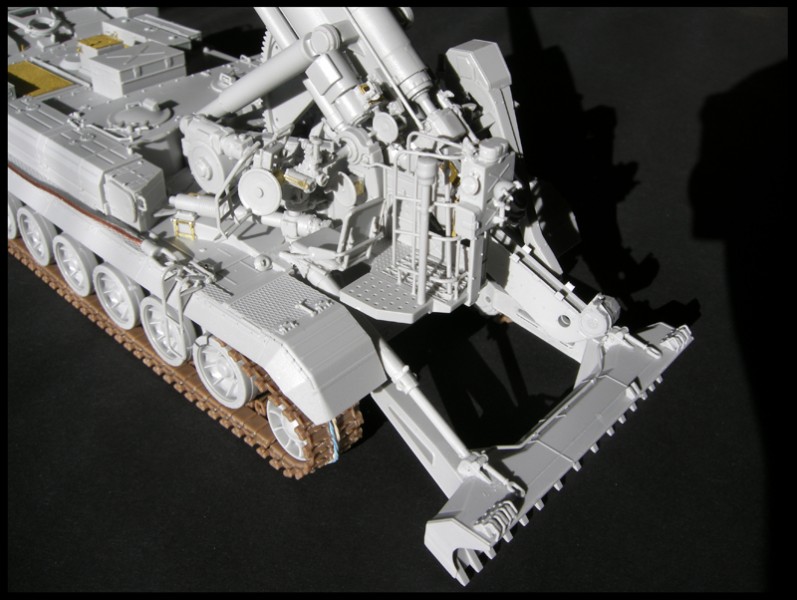
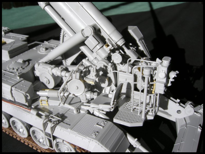
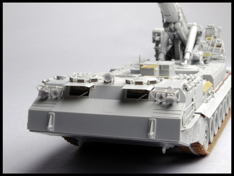
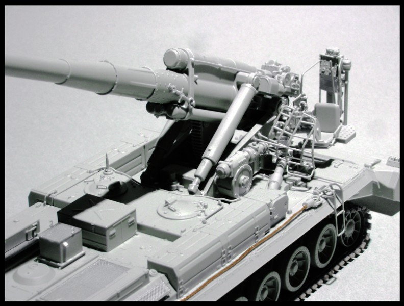
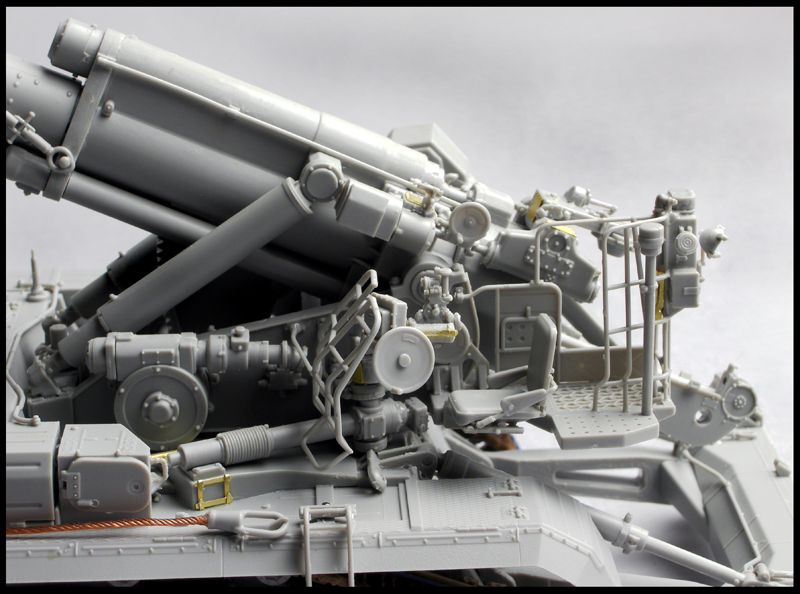
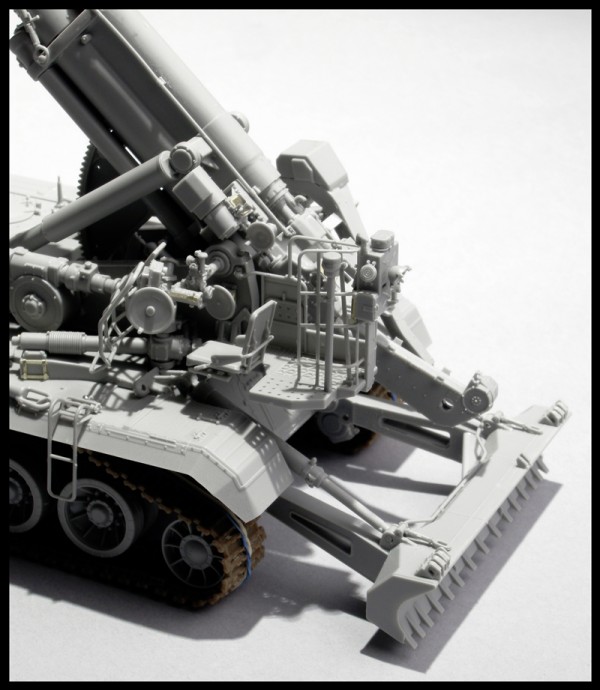
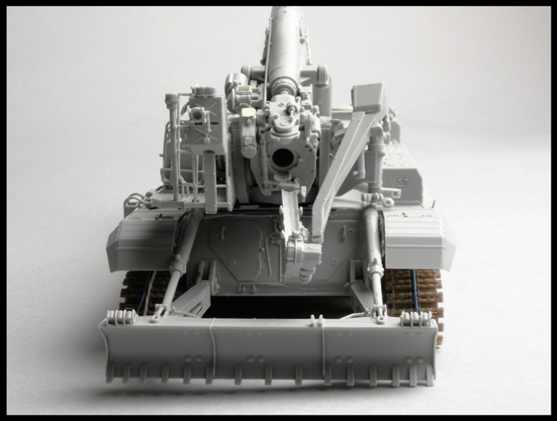
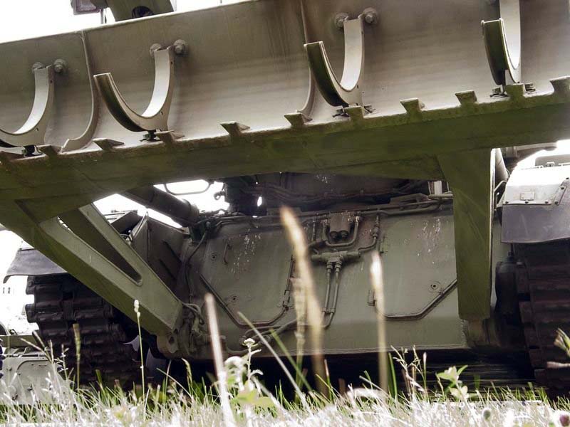
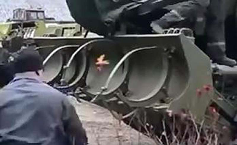
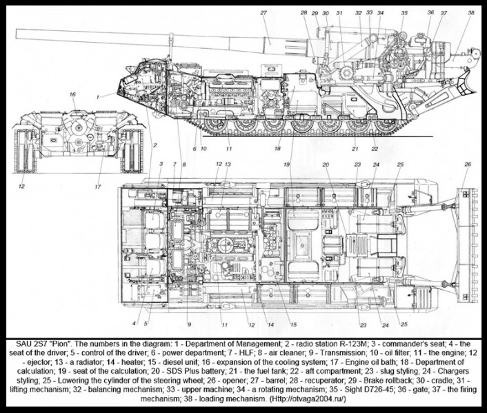
The cabin protrudes forward creating counterweight for the main gun. This fully enclosed crew compartment has seats for the commander, driver and two other crew members. The commander and driver are each provided with a circular roof hatch and in front of these are periscopes for forward observation. In front of them are windows that, when in a combat area, are covered by an armored shutter hinged at the top. In addition, there is a single forward-facing periscope in the forward part of the roof between the commander and driver. The torsion bar suspension has seven dual rubber-tired road wheels either side with the drive sprocket at the front and the idler at the rear(lowered to the ground in combat order),... looking like a backwards tank hull. Along either side of the hull are a series of large stowage boxes, along with the 203-mm gun, which is not fitted with a fume extractor or a muzzle brake, being mounted at the rear. One piston of the recoil brake and recuperator is located on the gun with the other two pistons beneath it and these limit recoil to a maximum of 140cm/4.6ft. The 2A44, when traveling is held in position by a manually operated lock mounted on top of the cab. Mounted at the very rear of the 2S7 is a large hydraulically operated spade that is lowered to the ground before firing commences. This spade digs in the ground approximately 700mm/28in and provides good fire stability. Standard equipment includes tank internal communication device, radio equipment, fire prevention equipment, an NBC system of the overpressure type and night vision equipment.
2S7 had its advantages and disadvantages.
The advantages were long range ( 23.3-miles/37.5-km with the regular HE round, while the nuclear round had a minimum of 11.2-miles/18-km, and a maximum range of 18.6-miles/30-km.The RAP round could go all the way to 34.2-miles/55-km). with this reach it had the ability to deploy and leave the firing position in short order; that upon inception, made it impervious to counter battery fire. Its fairly high speed (31mph /50 Km/h ) and good cross country mobility, allowed it to keep up with armored columns.
The disadvantages were very high cost and large size (Length 13100M Width 3380m Height 3000m ), absence of the turret and limited traverse ( Elevation range is between 0 degrees and 60 degrees and traverse range is 30 degrees (only 15 degrees to each side)., only carring 4 rounds for immediate use, as well as low rate of fire; 1.5-round per minute. This was later improved to 2.5-rounds per minute on the 257M.
CONTENTS
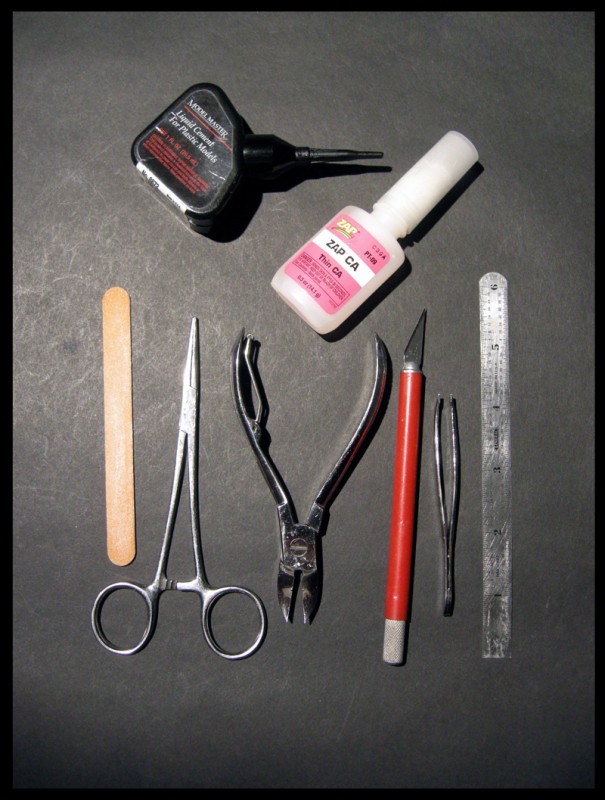
The kit is packaged to usual Trumpeter standards in a very sturdy cardboard box which contains the following:
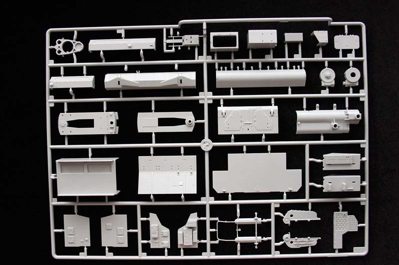
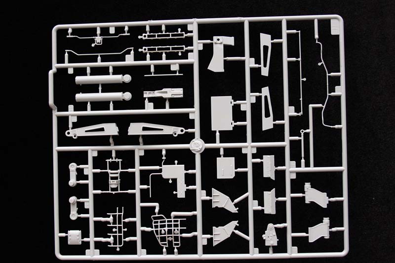
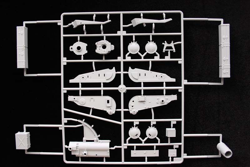
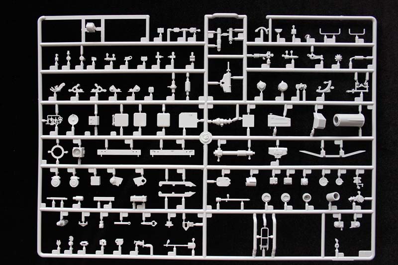
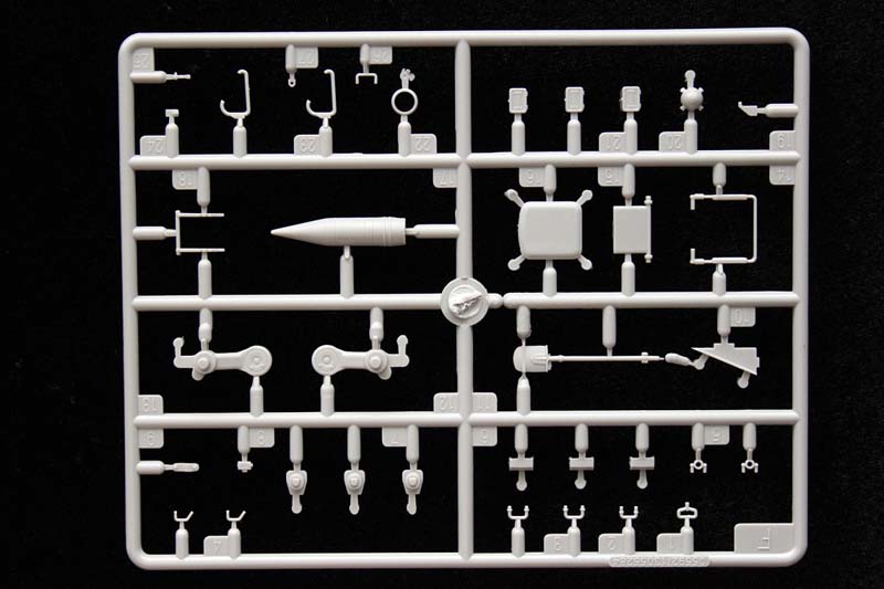
18 Sprues of grey plastic parts
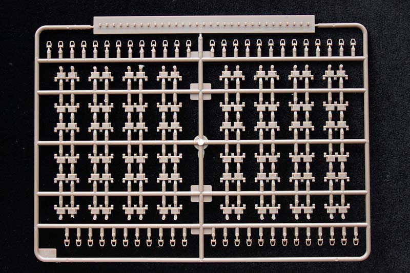
4 Sprues of Brown plastic parts (tracks)
3 Separate hull pieces
2 Sprues of clear plastic
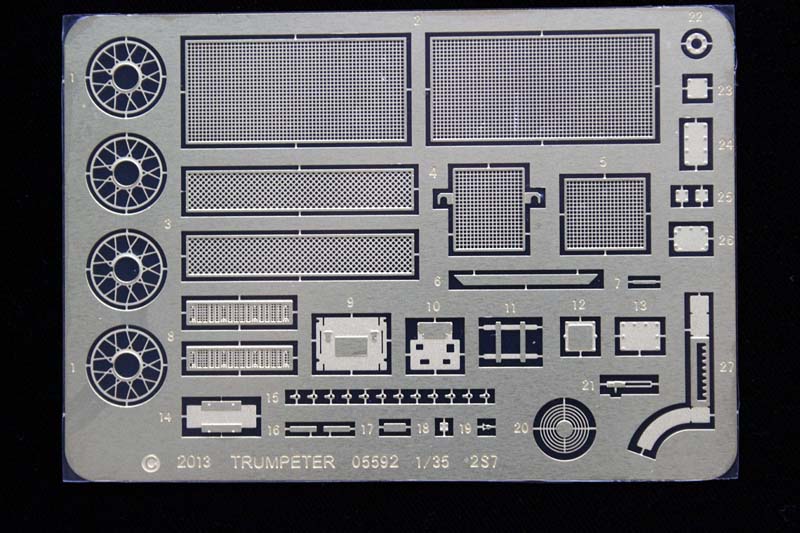
1 Fret of Photo-etched Parts
1 Length of Metal cable
2 Small rubber wheels
1 Decal sheet
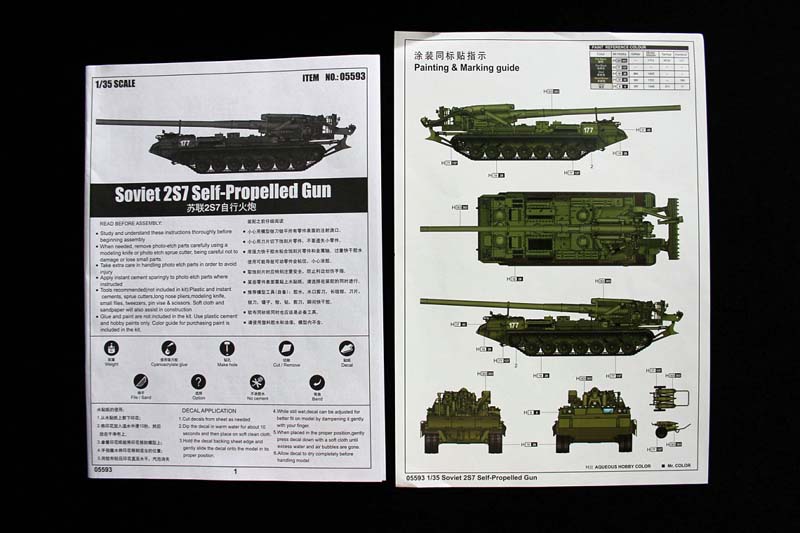
28 Page black and white Instruction booklet (35 steps)
1 sided color paint reference page With; Mr Hobby, as the primary paint referenced.
(Vallejo, Model Master, Tamiya, and Humbrol also referenced)
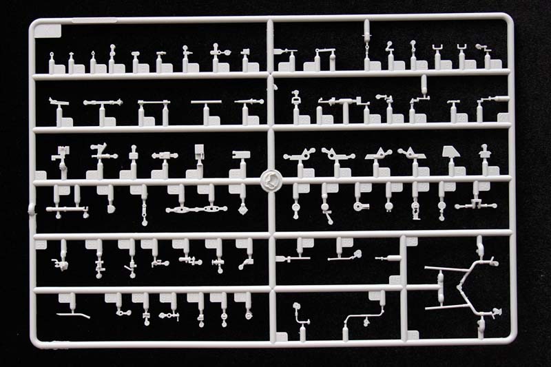
The parts are finely molded with no flash and excellent detail throughout.
Review and Build
As one of the largest artillery pieces placed on top of an extended tank base; more care and attention is needed in terms of studying the instructions thoroughly to determine the best build and paint order. Trumpeters instructions do a good job of staging the constuction for the most part, but there are a couple of steps along the way where altering the order bit, makes life easier. I've made note of these .
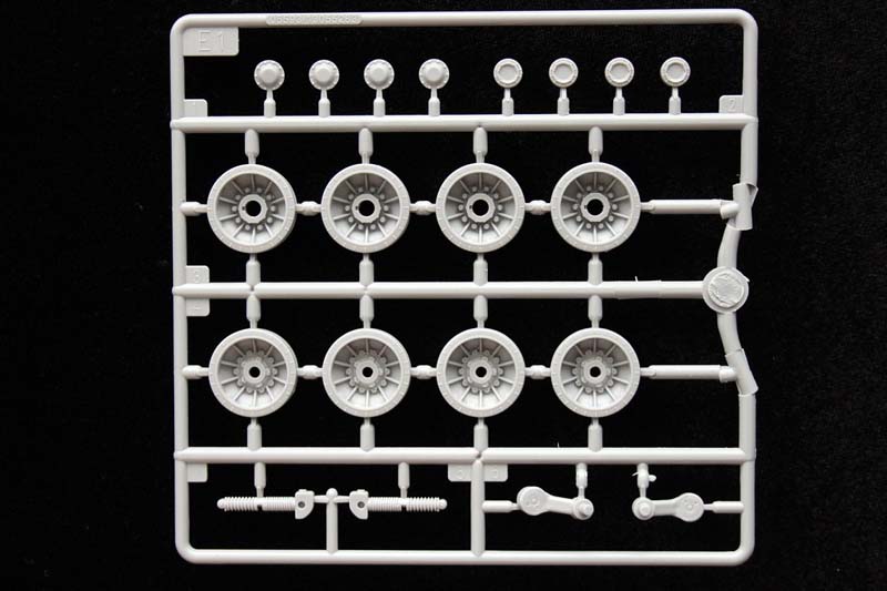
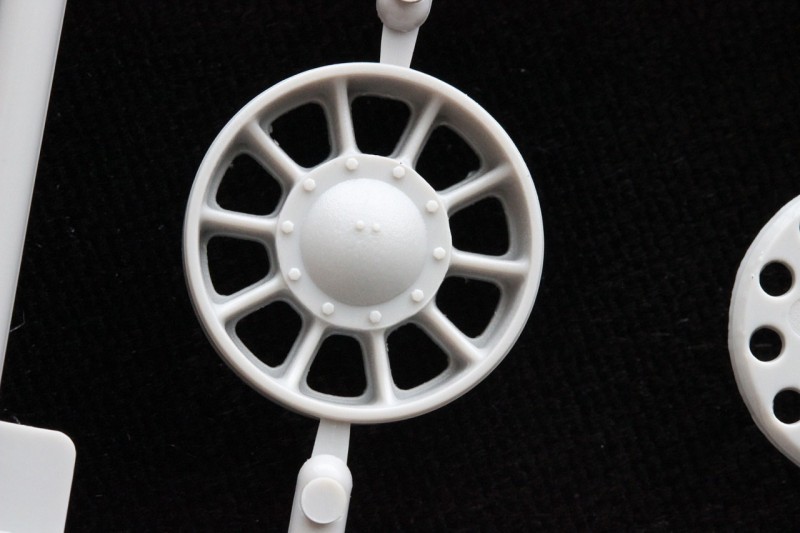
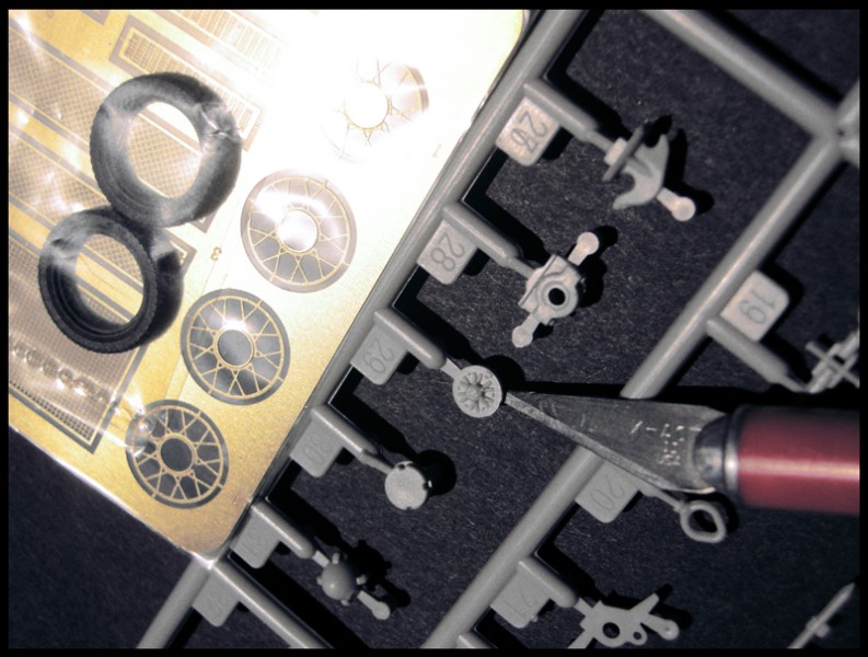
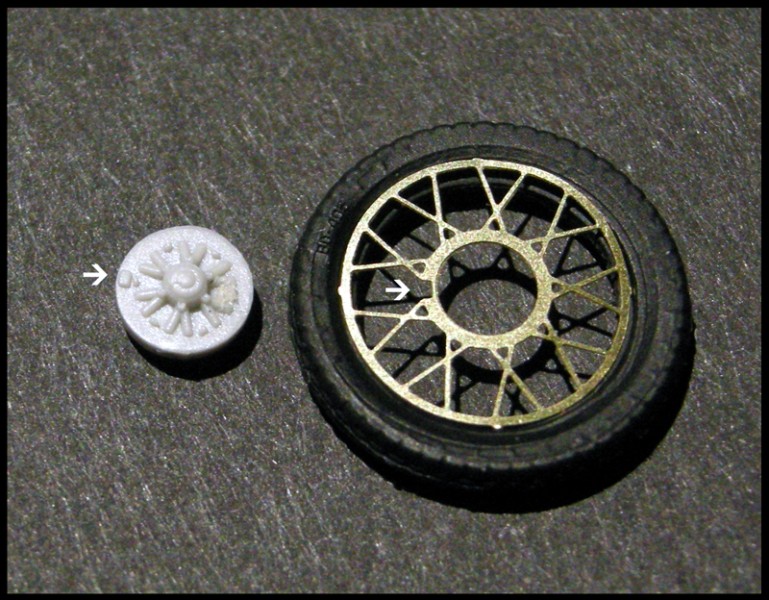
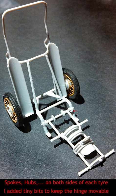
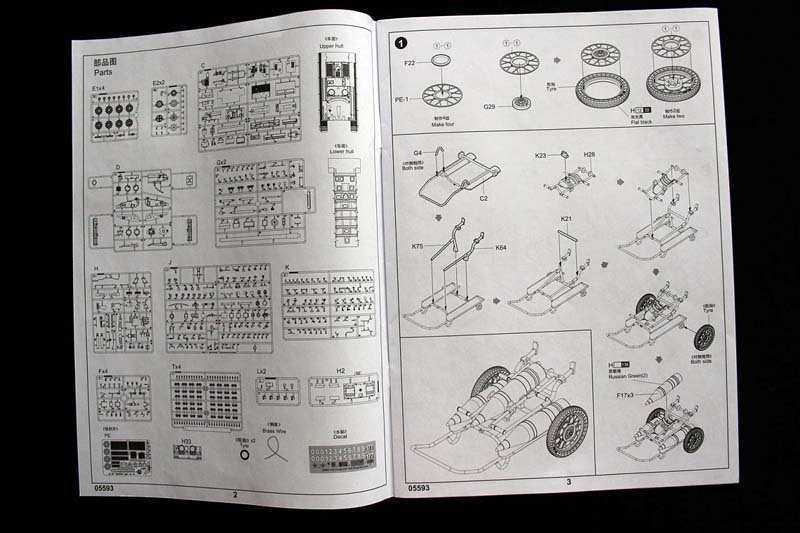
Work begins with... ['page 3/step 1'] unlike any other tank build I've seen, with the construction of a 'bicycle wheel like' ammunition carrier. The spokes of the wheels are photoetched, one each side of a tyre. (As I later got to Step 20's 'birdcage' I guessed that the small ammunition carrier, was possibly a small test to see if the purchaser is truly capable of the complications and details of this build.) Right off the bat you are foreshadowed. The kit is complex and the instructions are not always detailed enough. The positioning keys are drawn, but not called out.
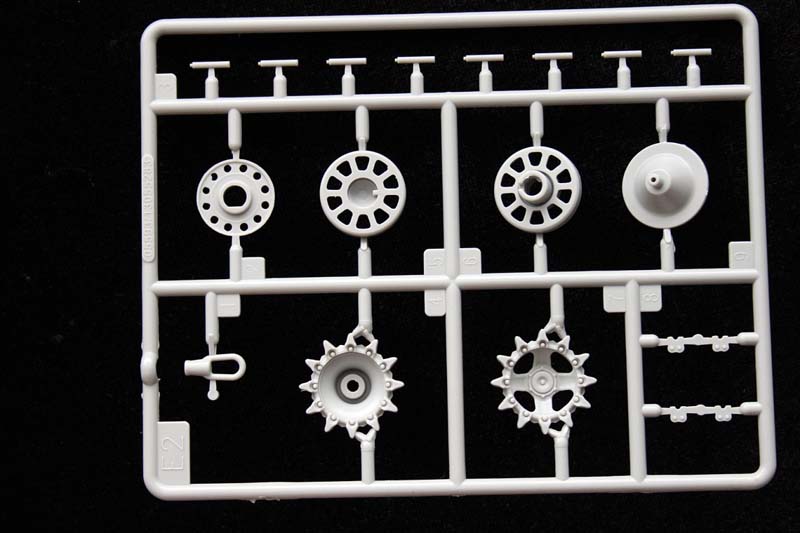
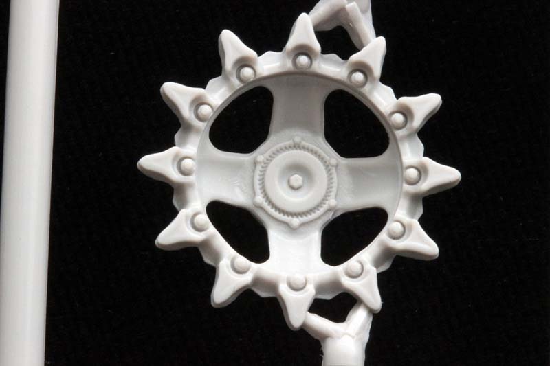
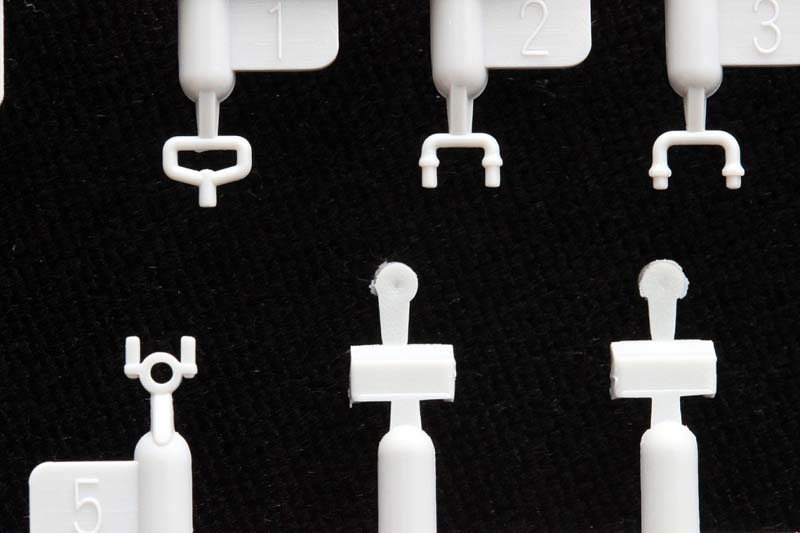
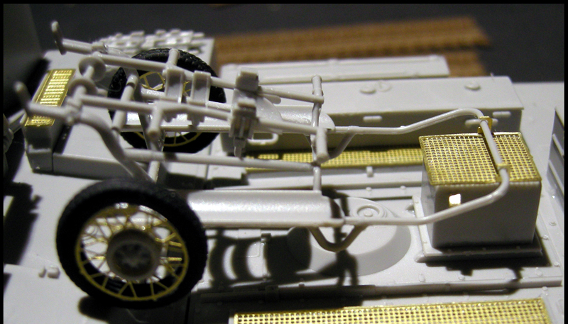
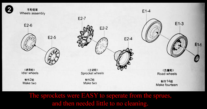
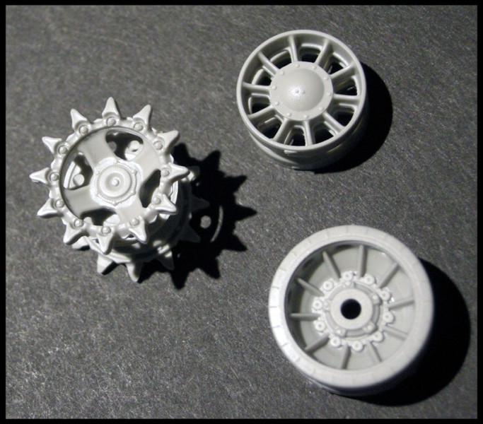
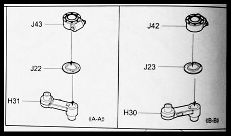
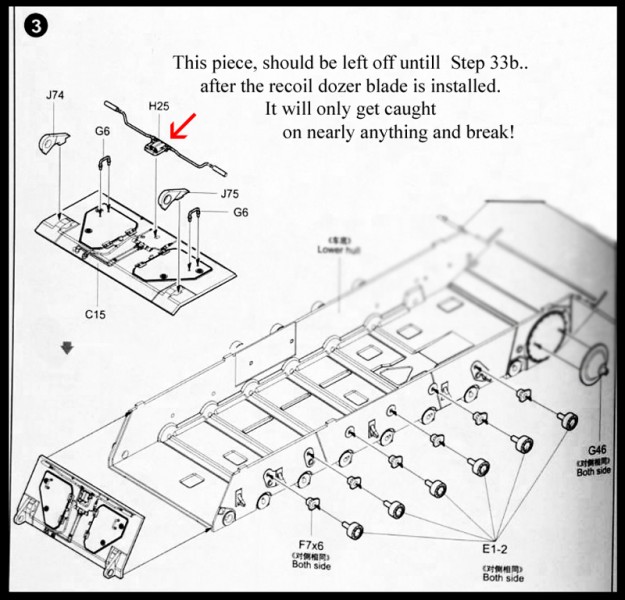
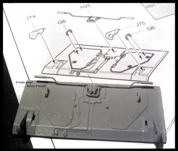
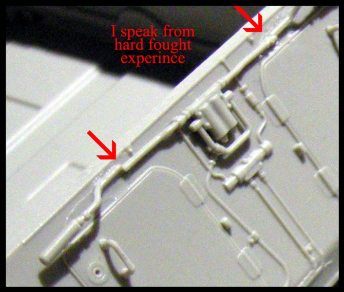
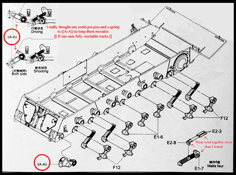
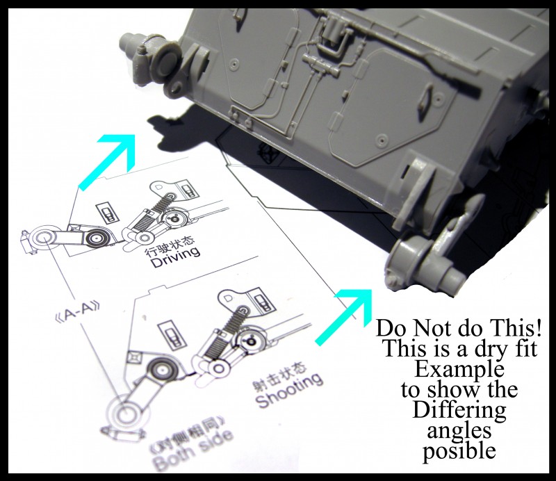
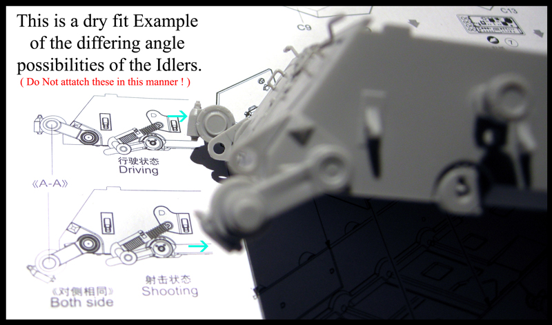
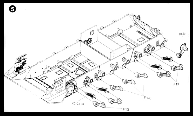
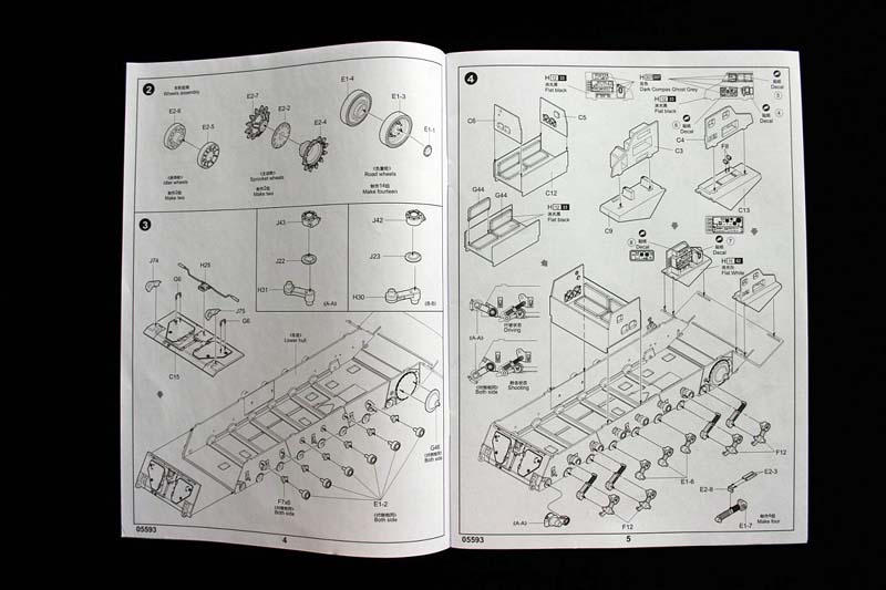
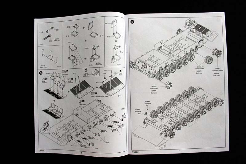
Wheel assembly ['page 4/step 2'] is next up; however I postponed the wheels until after I finished the lower hull assembly ['page 4/step 3 through ''page 6/step 5']. Of note: I recommend delaying the attachment of part H25. The suspension arms in steps 3,4,&5, are nicely detailed and fit well. The sprocket wheels are finely molded; and the ease of trimming E2-7 & E2-4 off the sprues was so gracefully easy, unlike another review of a different company I did last year. At the bottom of the page - putting on the roller arms on the right side. Be sure to use the correctly numbered arms (F-12 and F-13 are side specific). I found the small pistons (stopping hydro absorbers) easier to make than I originally thought. Nice detail. Remember to not glue in 'A-A' (nor 'B-B' on the next step); until you've decided what position you want for the final display: Driving or Shooting.
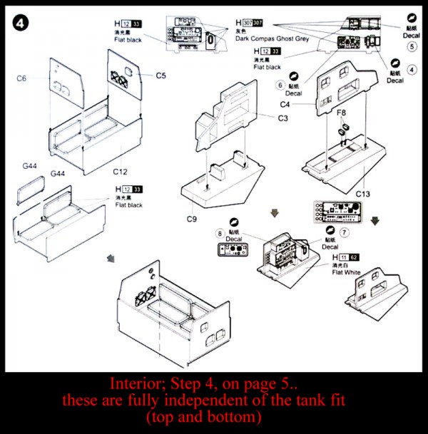
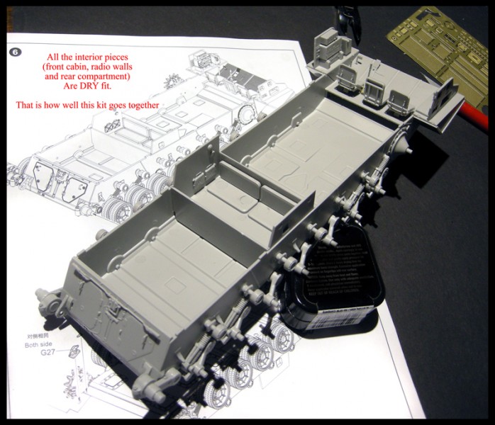
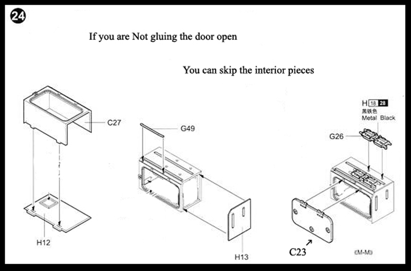
Starting with ['page 5/step 4'] the instructions work with the interior of the hull, driver's compartment and crew section. Note: you can build the model without using any of the interior parts. If you don't attach any hatches in the open position, the interior is hardly visible. The fit of the rear compartment is so good I forgot I didn't glue the sides C-5 & C-6 to C-12 or C-4 & C-3 until I took the kit apart in photo 2S7_Page_28_Step-34_&_35_Photo01B . Its really great you can build the kit nearly in entirety and then decide if you want to put a lot of work into the interior. Also, the quality of the lower hull fit - would make an after market engine/transmission/generator and armament carriers - easy to drop in. It would elevate this kit to the heights of completeness achieved by Meng Models M2A3 with Busk. I have one question though...where does the crew of the center interior section put their legs? ...Maybe the two benches are actually futons? (with huge ejection pin marks) Continuing on the interior ['page 6/step 5'] you can see that the subassembly C-11 drivers compartment fits so snug into the lower hull I didn't see the need to glue it in until my final fitting (around Step 30)
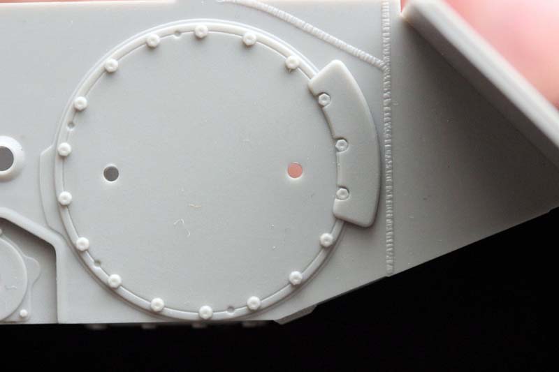
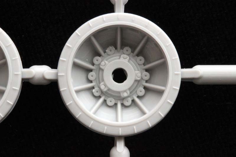
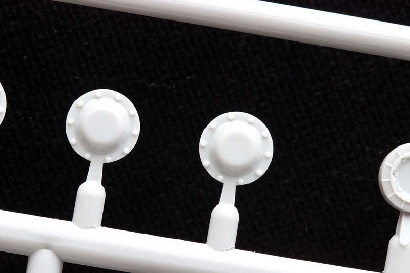
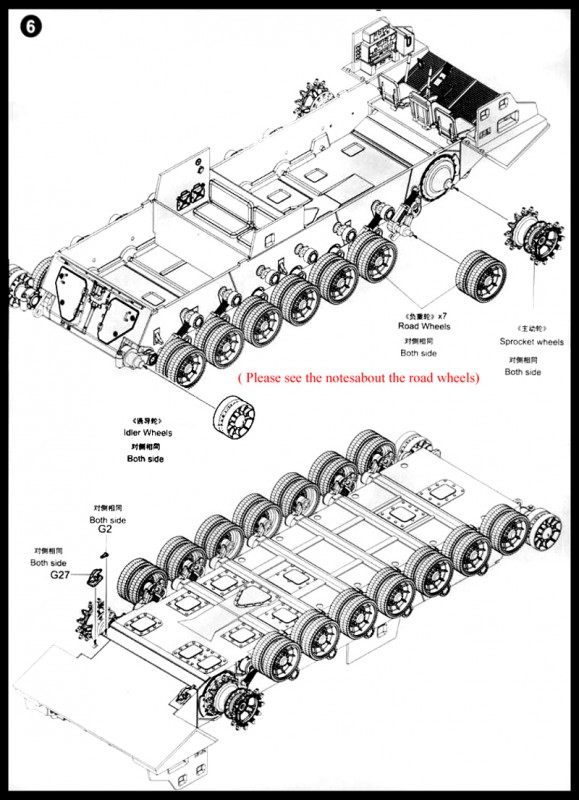
The instructions show finishing the lower hull with ['page 7/step 6'] with Idler, Road, & Sprocket wheels.
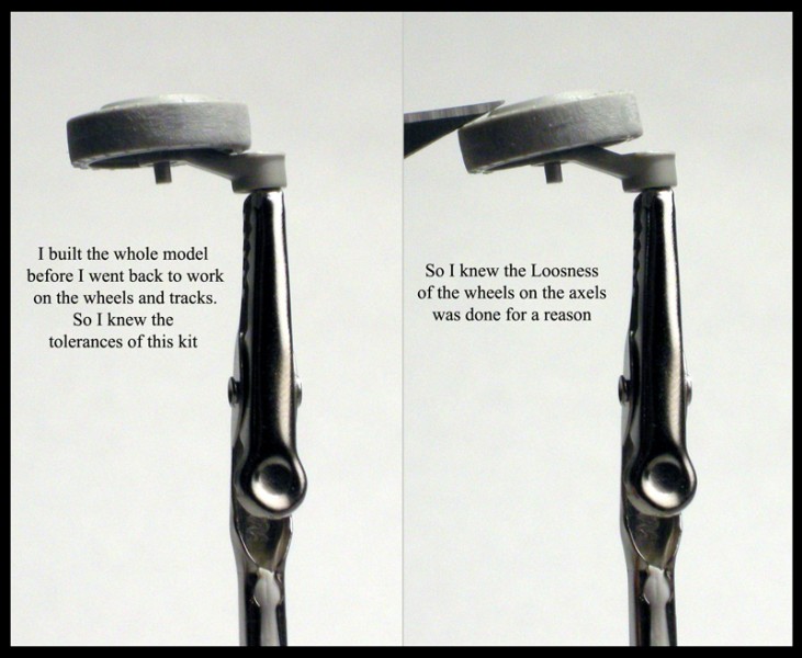
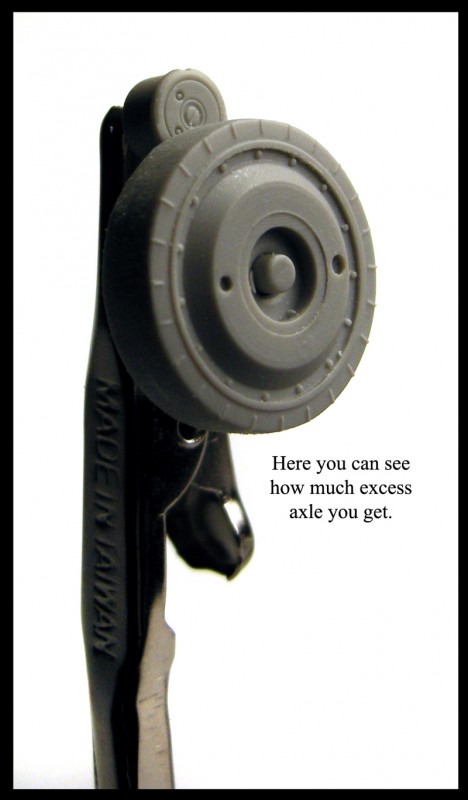
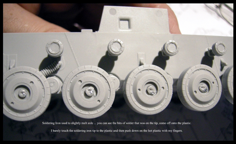
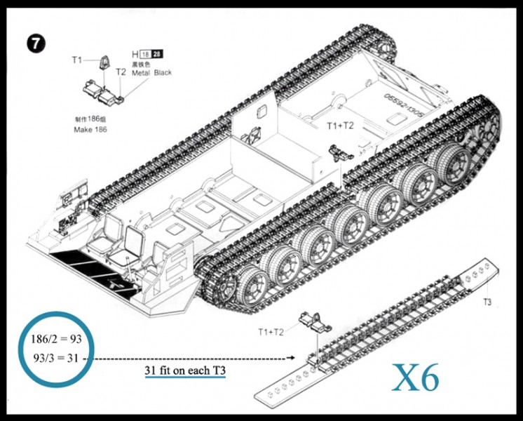
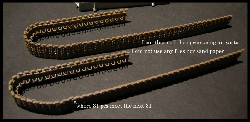
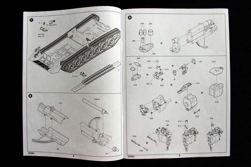
As shown in photo 2S7_Page_04_Step-02_C I postponed the wheel attachments until Step 30, as I also did with ['page 8/step 7']. I also postponed the track build until I finished the entire model (NOTE you must put on the finished tracks Before gluing the top hull to the lower hull). For this model I am forced to agree that individually glued together tracks are most appropriate. In all my research I did not find any photos of relaxed track slump along the return rollers.
Step Eight:
I remember what it was like the first time I read Tom Clancy's "Red Storm Rising". I stayed up to 5am for days, unable to put the book down. The complexity, the pace, and it was well written to boot!
[ https://en.wikipedia.org/wiki/Red_Storm_Rising ]
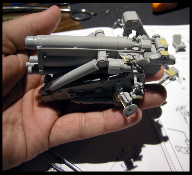
That is exactly what this build felt like to me; from step eight through step twenty one, I was fully immersed in the pieces, their complexity, workability, and their fit. I haven't had that absorption effect about a model in a very long time.
Step nine:
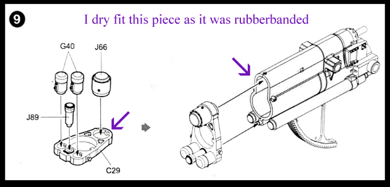
Easy; G40s are keyed. J66 is keyed
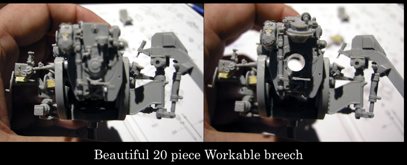
Step nine B:
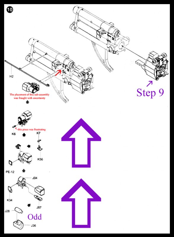
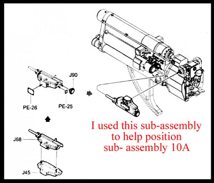
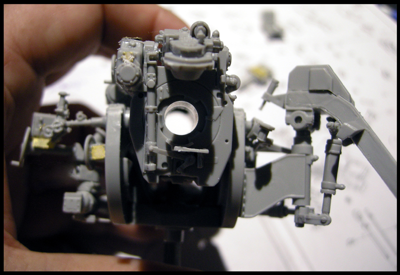
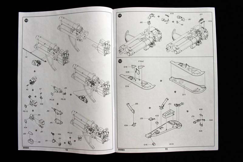
Here is this wonderful 21 piece Workable Breach It looks like K42 and K62 are meant to be workable too, but I was not easily able to figure out exactly how and gluing it in a certain position left the Gun Plug still able to move. Step ten: Here is a subassembly running up the left side of the page. The entire kit only gave me eleven fit challenges...three of those are on this page. J36 is not keyed to J4. K6 just took 5 tries to fit, and the placement of the finished subassembly is a guess; that I used the middle subassembly of J45 and J68 as a guide to where to glue it down to.
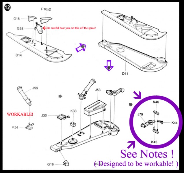
Step twelve:
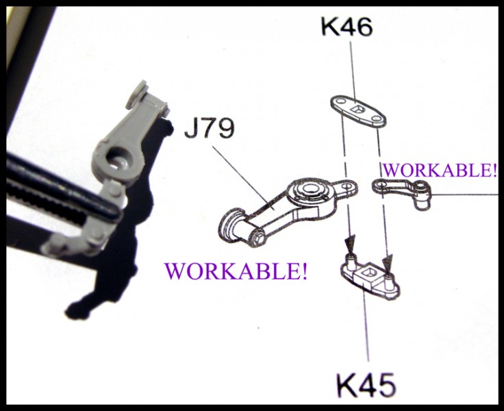
Be alert in trimming G38 off the sprue. I messed up and trimmed off the retaining straps. G18 and F10 went together with a nice tight fit J99 is WORKABLE - do NOT glue to K54 (instructions forget to mention this). The sub assembly in the lower right hand corner of the page is a three point working part be careful how you make this.
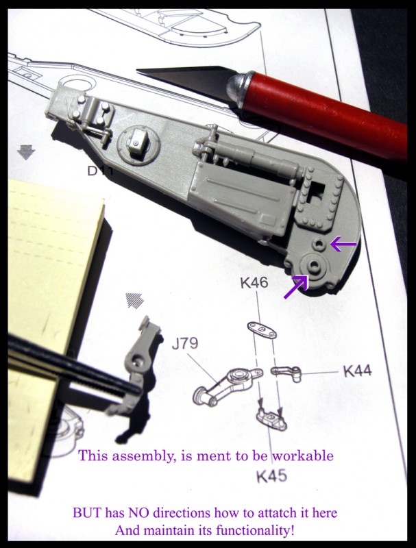
Here is where I'm going to question the intent of the company that put out the kit and its instructions. There are SO MANY Workable pieces to this kit; but they don't write out the exact steps to use/understand the 'why' of these options. I fail to understand how any company can hope to gain the top place in the hearts of their customers, or the highest status, spoken in Honor, if they short change the intelligence of quality modelers. I mean how much can an extra page or two add to the bottom line; of these new, complex, and expensive models.
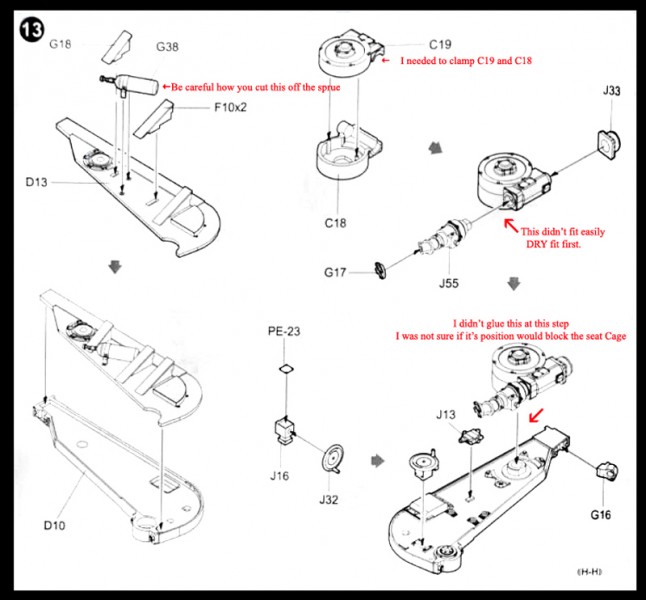
Step thirteen:
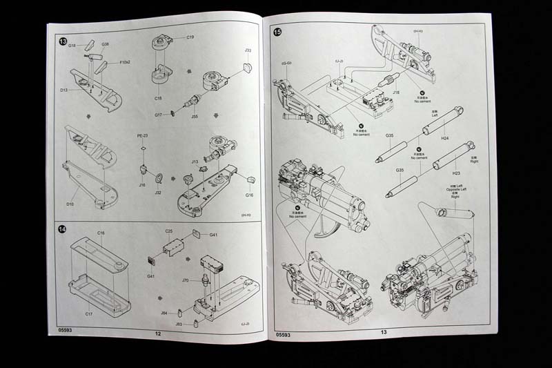
Very similar to Step 12. I had to clamp C19 and C18, these pieces were the worst fitting of the entire kit for me. But a clamp made it work. J55 didn't fit that easy either. This finished assembly was loose at its attachment point, and I wasn't sure it would block some of the birdcage places of attachment; so I waited to glue it in place until the end of Step 21.
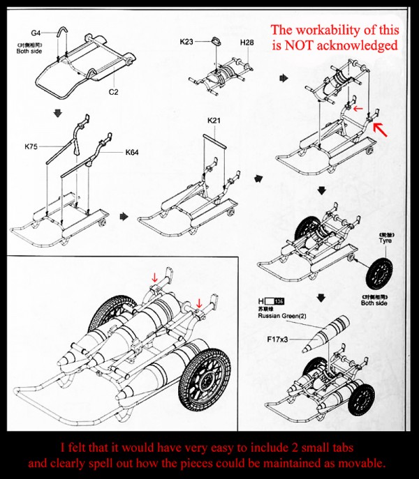
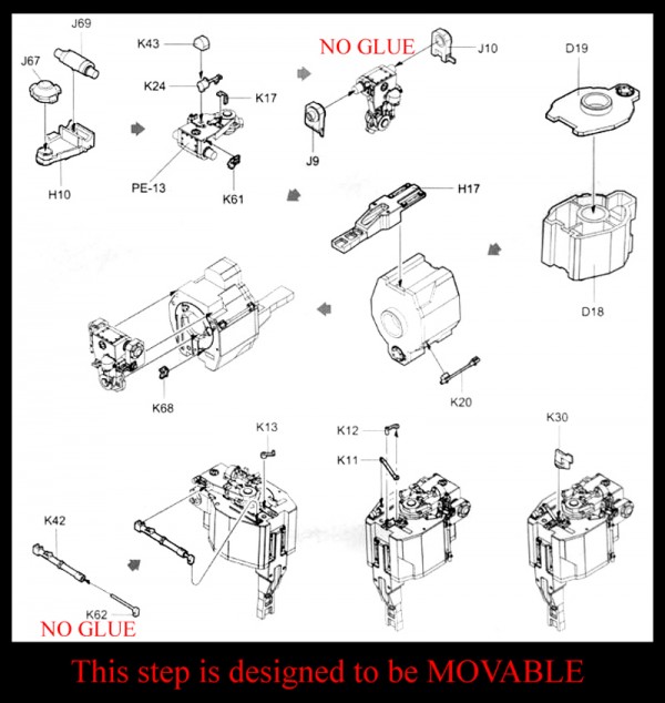
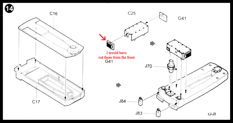
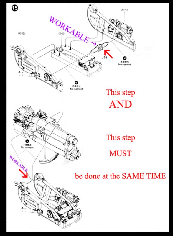
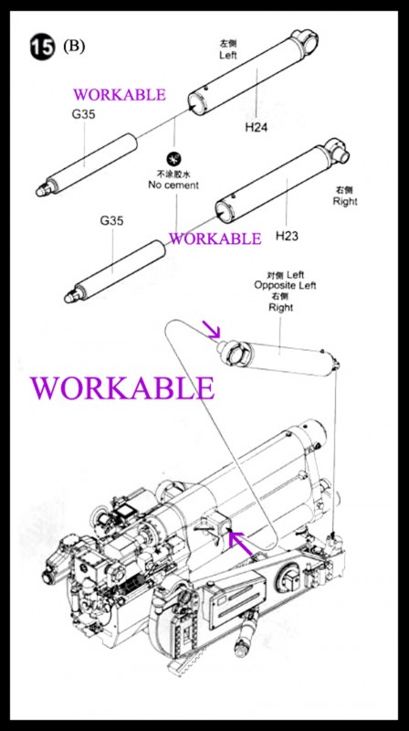
Step fourteen and fifteen were fairly easy, although I'd cut parts G41 off the sprue from the front so it wouldn't chip out the part's face. Finally the instructions say "No Cement". Put the gear and the gun in between and at the same time. Stubs on H23 and H24 are the guide to the side they go on.
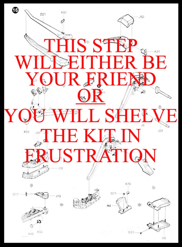
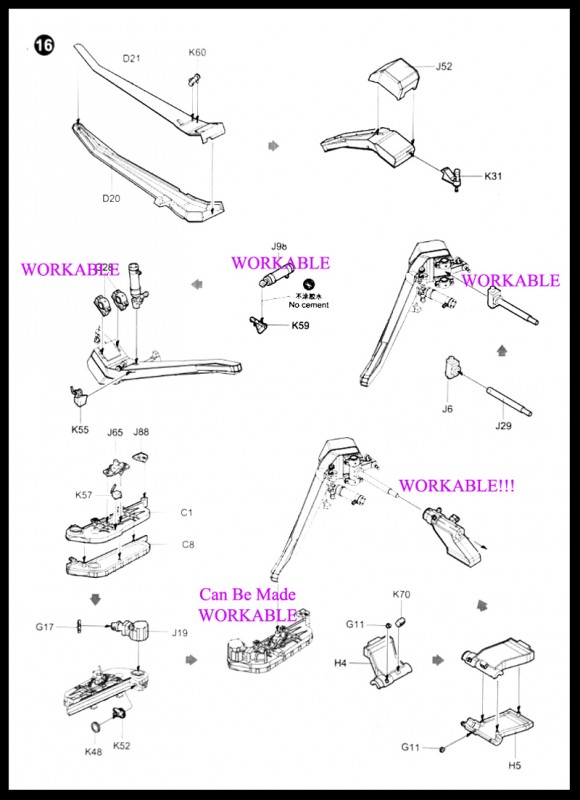
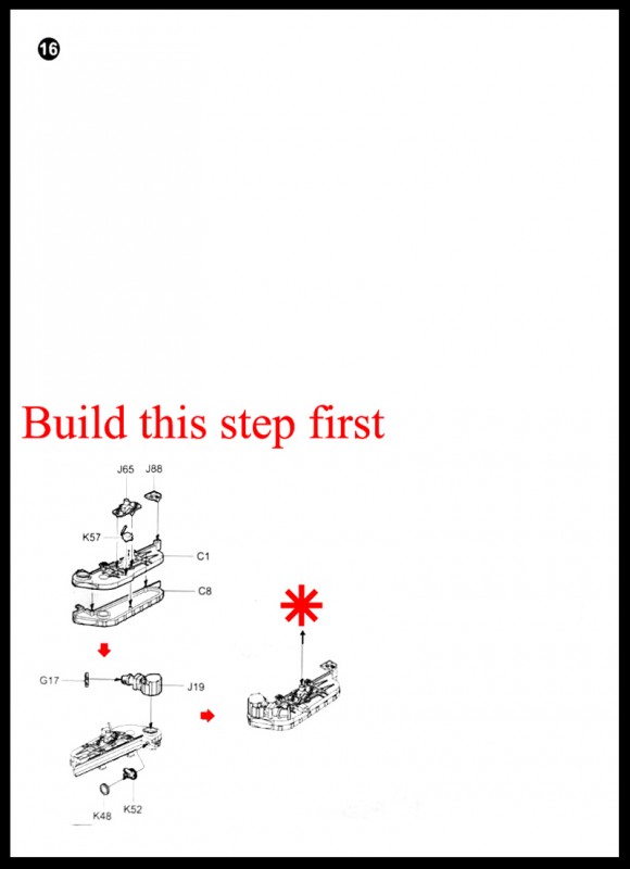
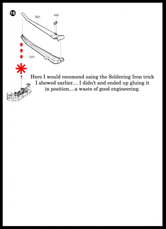
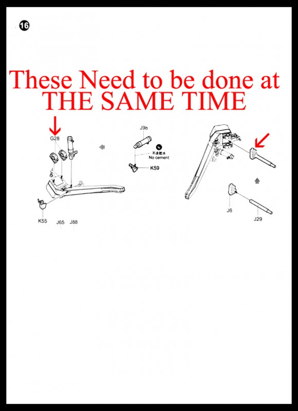
Step sixteen, was difficult because there was no heads up what was coming. I think my photos '2S7_Page_14_Step-16' through '2S7_Page_14_Step-16D' explain this page. The changes in order and attachments are Only My Opinion.. Always dry fit / test .... then glue ....Maybe )
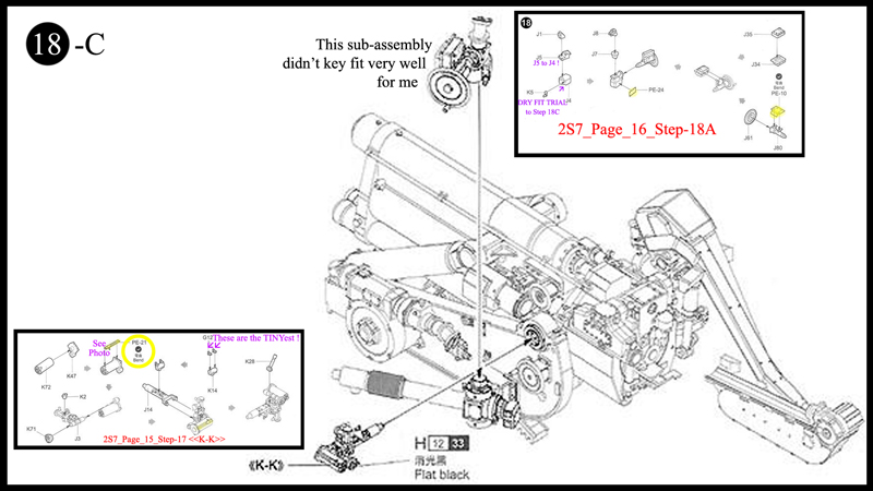
Step seventeen:
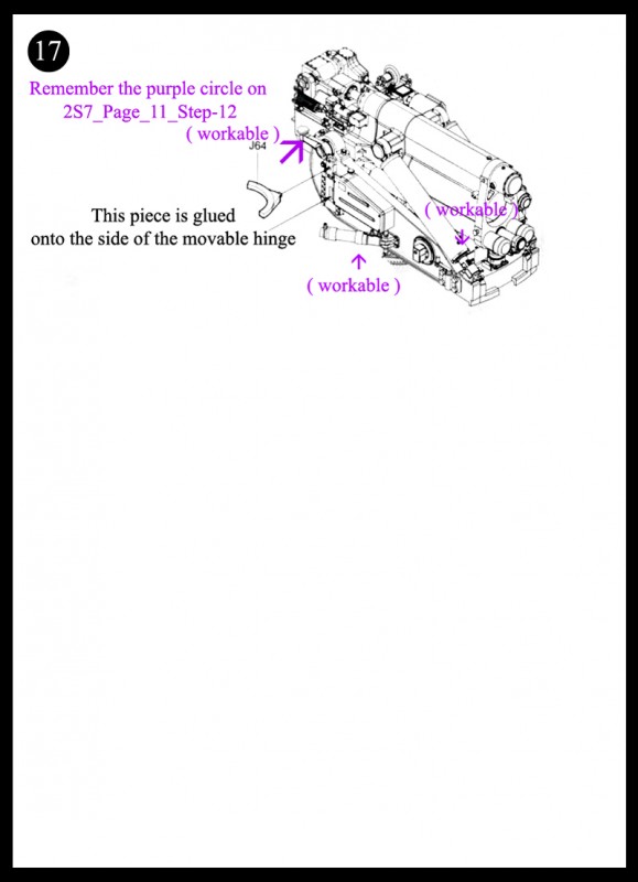
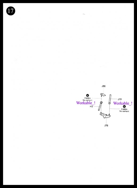
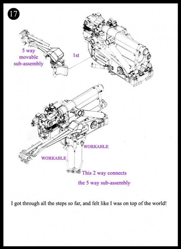
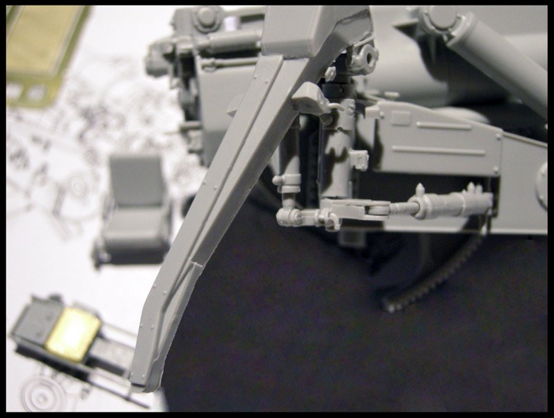
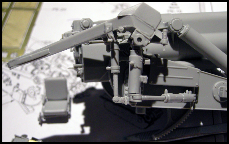
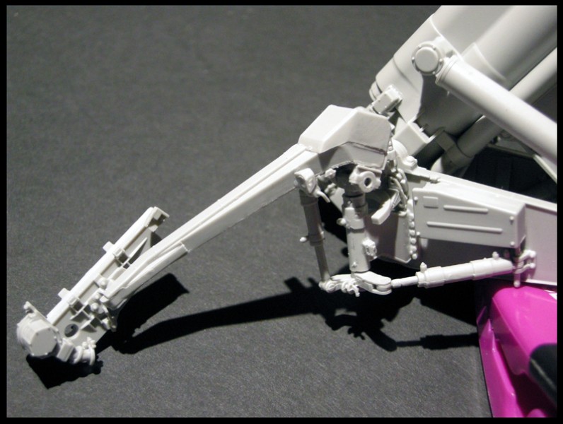
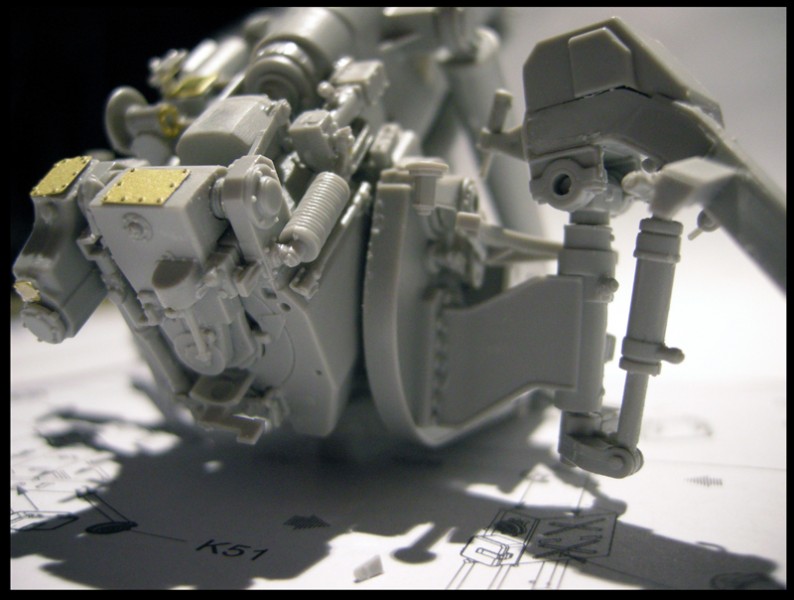
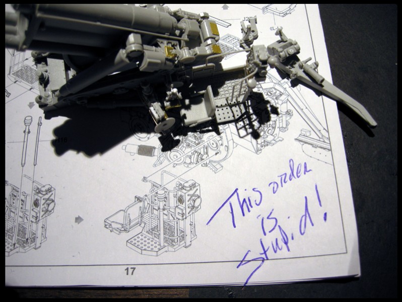
Gluing J64 in place brings to fore a problem I encountered. Because the entire shell loading crane is made to be workable, any movement will knock off the workable assembly you made on the lower right hand corner of page 11. There should be an explanation of how all these pieces should work together. After all my troubles at the end of page 17. I ended up just gluing the dang assembly in the purple circle on page 11 in a guesstimated position so it wouldn't interfere with the shell crane's functionality. Its frustrating because you do a lot of small and complicated work and the instructions leave you short. The next subassembly is the easy part to make the entire crane workable ... be careful jamming J15 into J76. I sanded J15 a VERY small amount to get the fit.
We now tackle the (just as complicated) other side of the gun cradle.
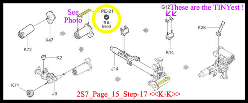
At the bottom of Step seventeen on Page 15, is the assembly of very small pieces. I wrote down on my instructions page, that G12 was TOO small. Also I flailed around with the placement of PE-21. All it would have taken is the inclusion of a photo (The following images are used for discussion in this not for profit piece of Journalism) like 2S7_Page_15_Step-17F.
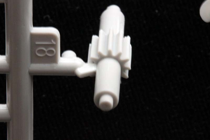
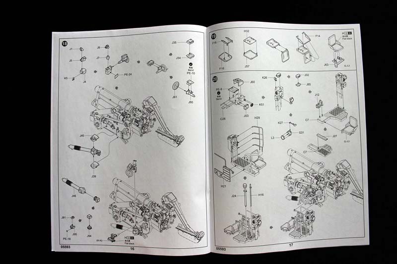
Step eighteen:
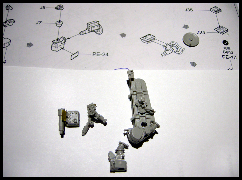
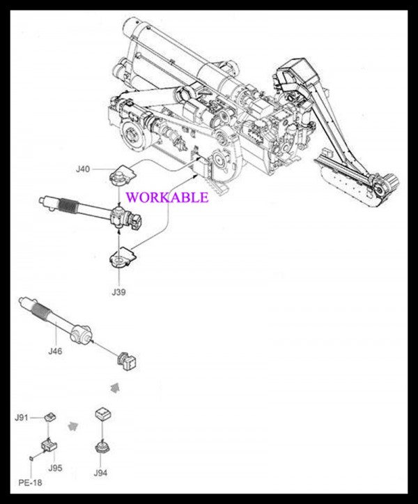
It gets harder here.... I struggled with J4 and J5 placement my keys didn't catch. On the top right of the page... PE-10 says bend... but gives no side view example of how... J46 is workable...instructions should warn 'No Cement between J40 and J39. I had 'keyed' issues with the subassembly at the top of the page and its final spot on J40.
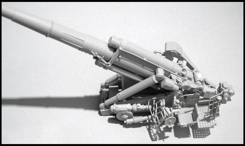
Oooohhh at this point ... I had to sit back and admire my work.
Even More Complexity on the left side coming.
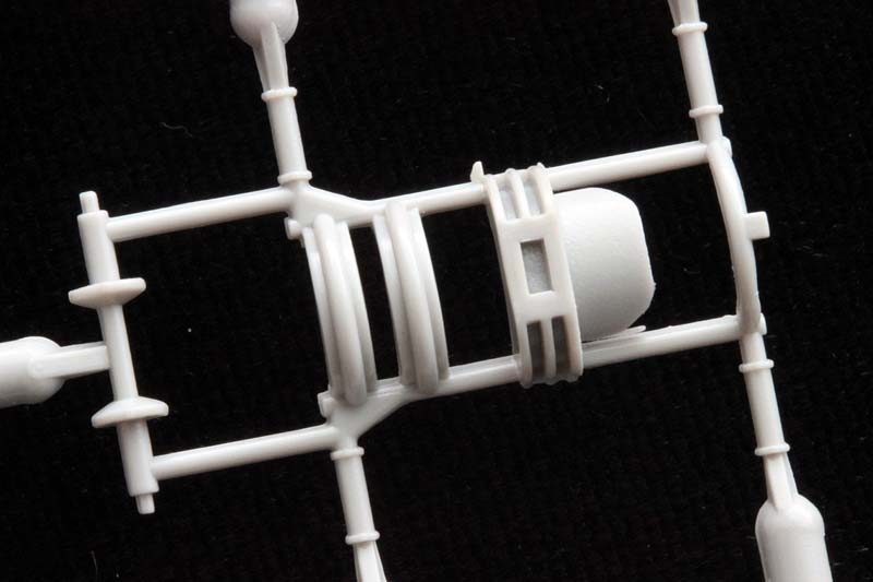
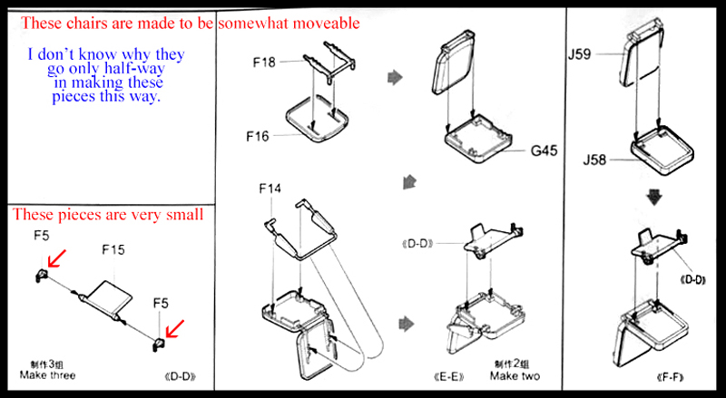
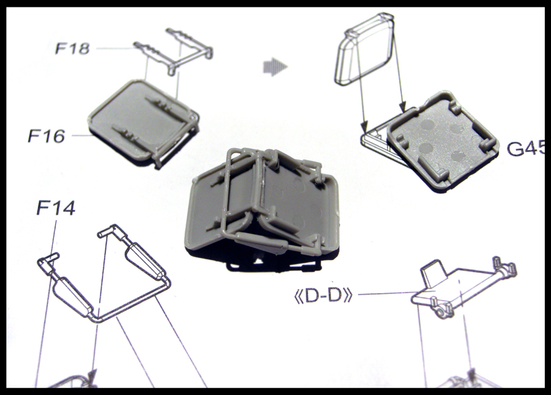
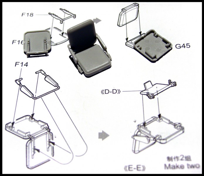
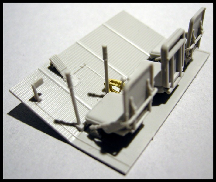
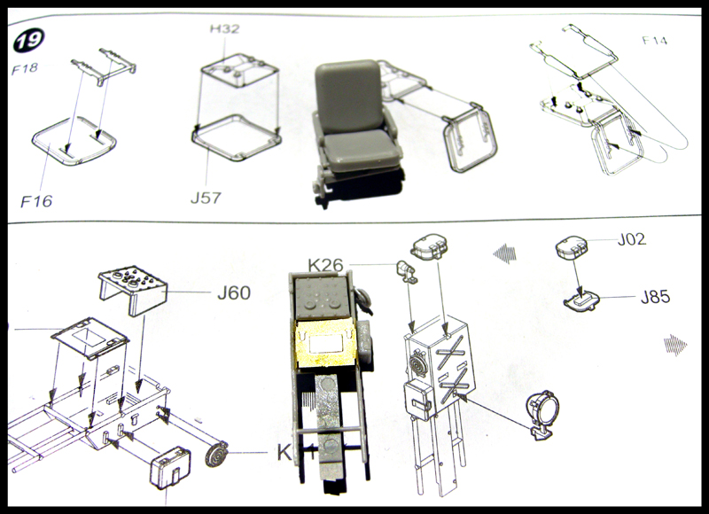
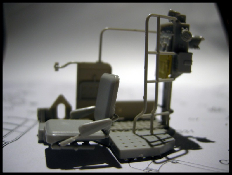
Step nineteen: Great detail on the seats. I wish the seat had been fully functional foldable.
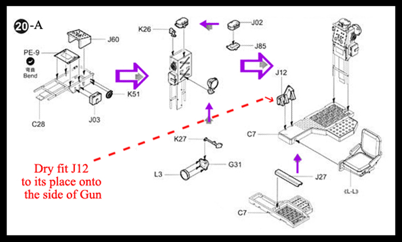
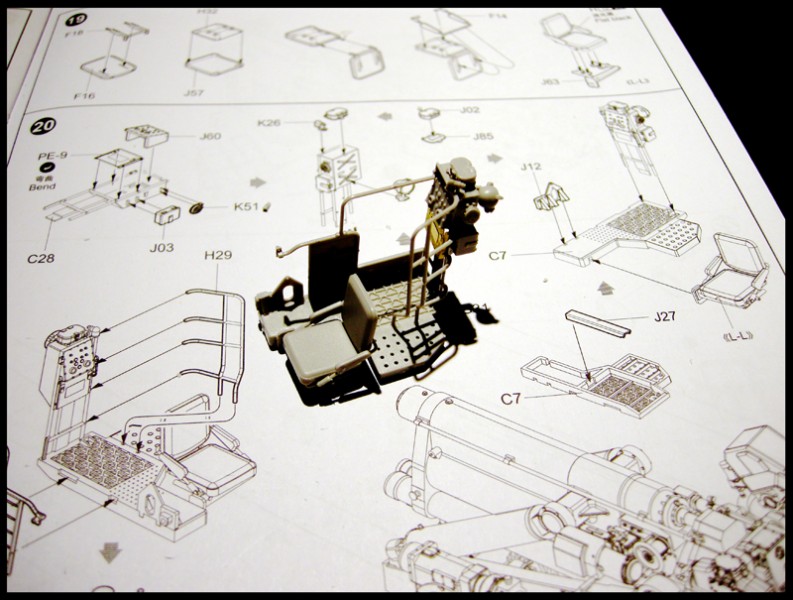
Step twenty: PE-9 again gives no side view example of how to bend it.
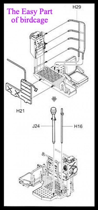
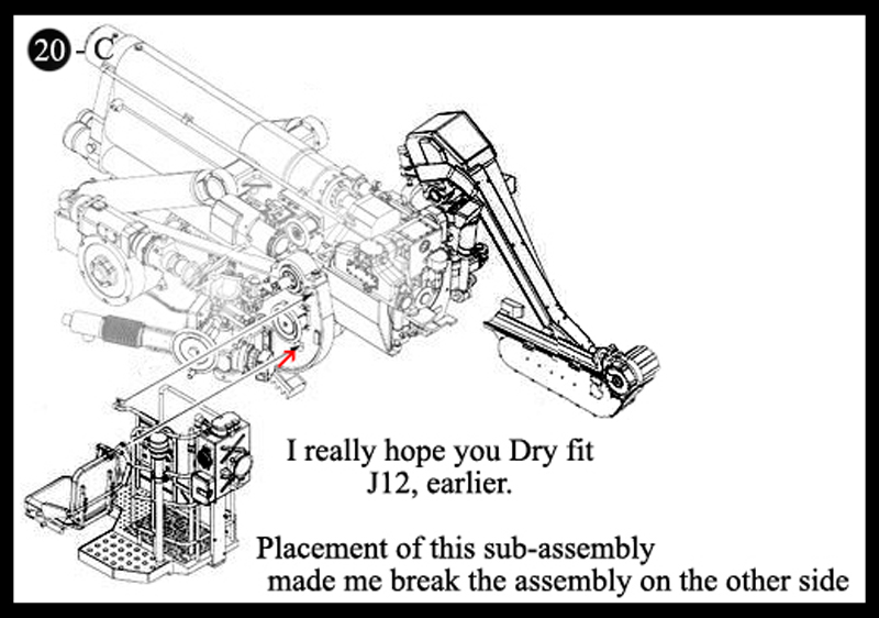
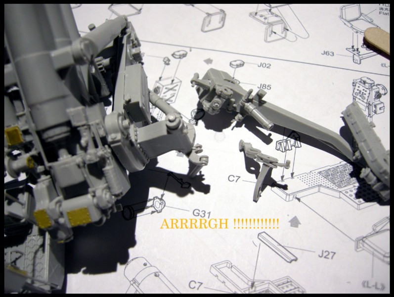
The attachment point of the entire subassembly in Step 20 is by J12 to D10 ! PLEASE test this fit before the whole bird cage assembly is even made. Once its made and then you have any difficulty, you risk breaking other parts of this complicated gun. (As I did) All that work.......to keep things workable :-(By step twenty-one we are gluing on the front bird cage in place by 3 little points of contact Let the cage fully dry! ...then I glued the subassembly from step 13 in place.
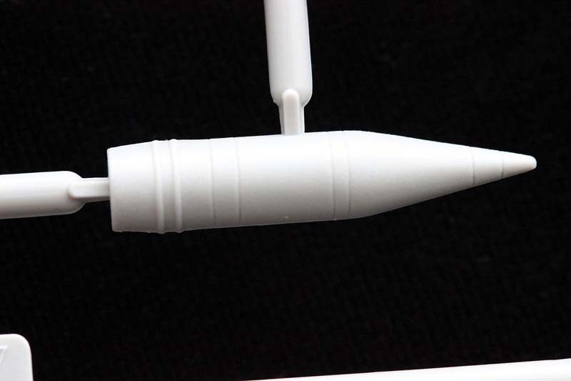
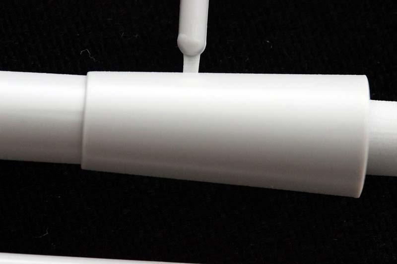
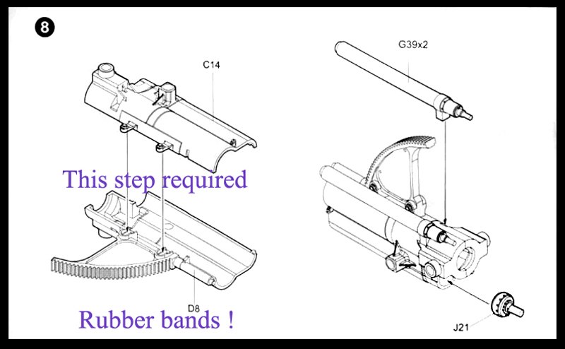
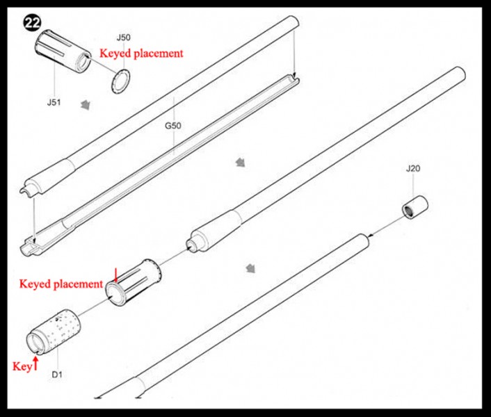
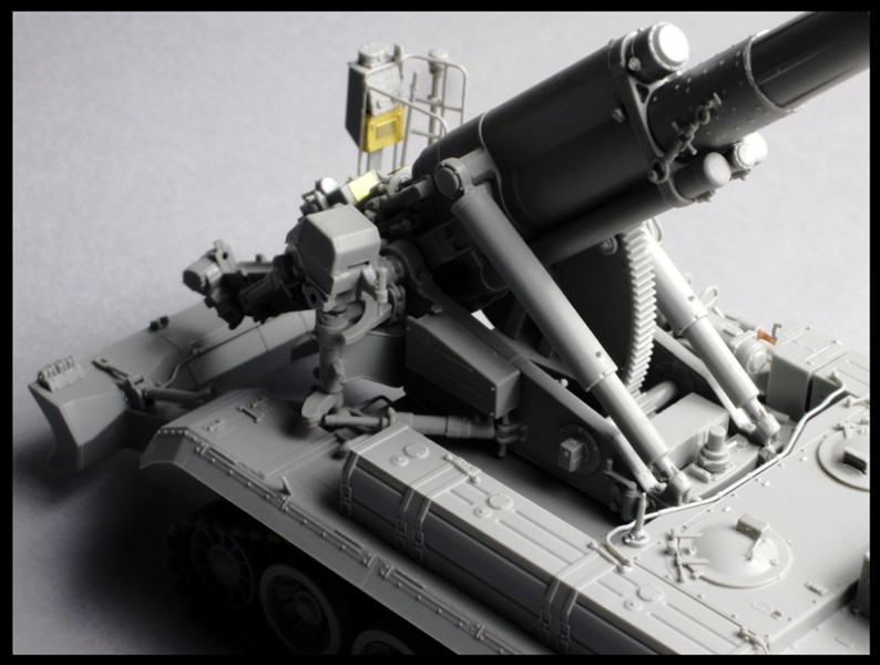
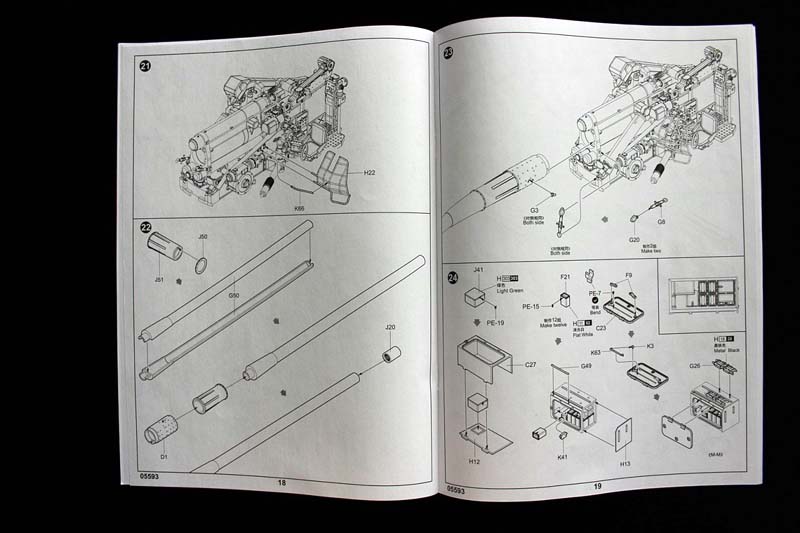
The gun barrel went together for me like a charm, in step twenty-two. Using rubber bands to keep the fit tight; I put glue drops on the inner seams to hold the pieces together. I love AM metal barrels, but in this case it seems to me I wasted money when I bought the $12 barrel. ( Yes, for me the fit and clean-up is that good ).
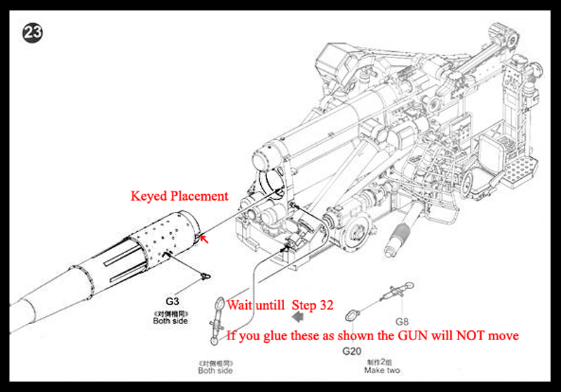
An Important step (twenty-three) that is NOT explained... If you glue the G20/G8 combo as it shows you will NOT be able to raise the Movable Gun!
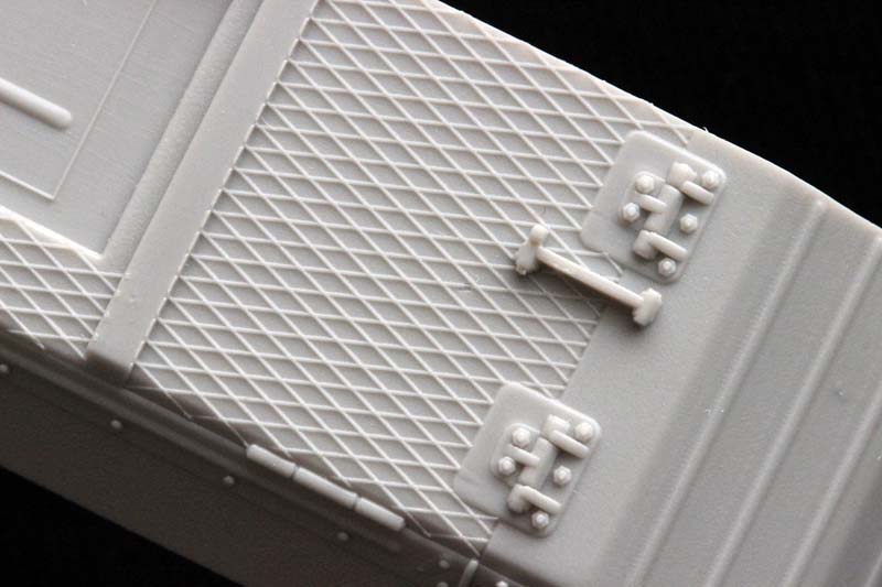
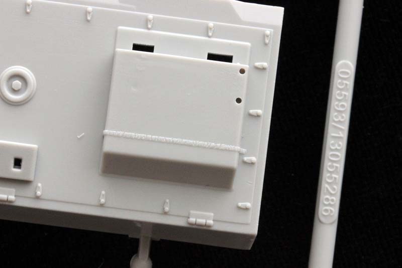
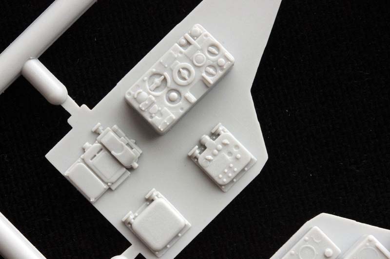
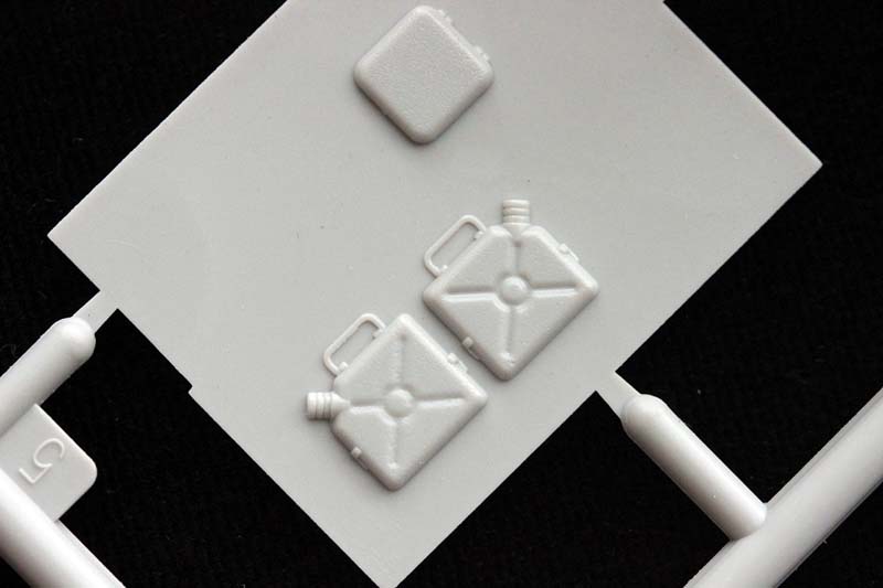
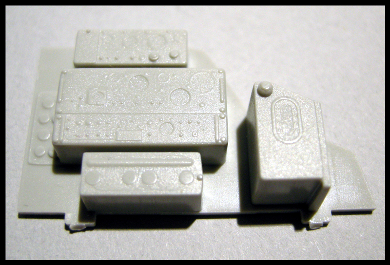
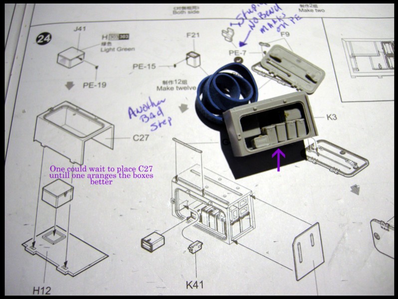
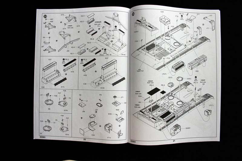
Starting with step twenty-four we are constructing stowage boxes, and other hull add ons. PE-7 is a bit freeform; ithas no marks on it to show the bending points.
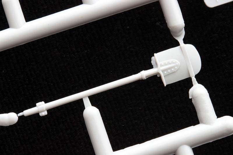
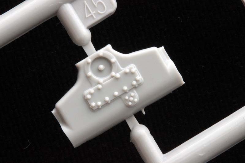
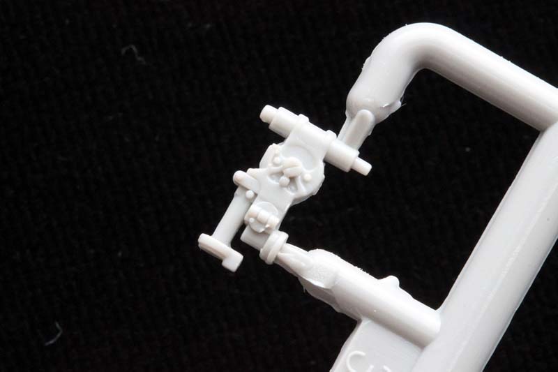
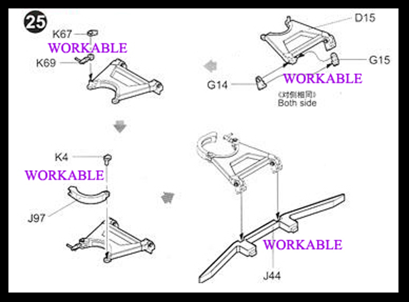
Step twenty-five A starts with the barrel lock Be Careful with the glue... the gun lock is made to be functional.
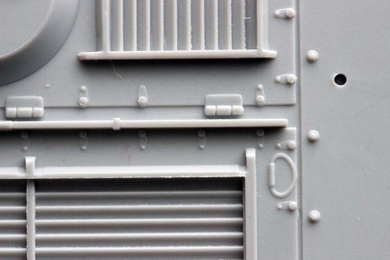
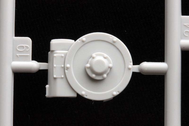
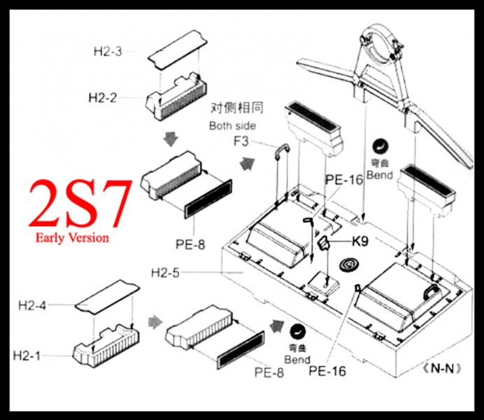
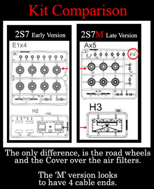
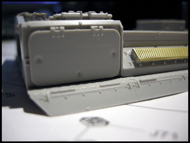
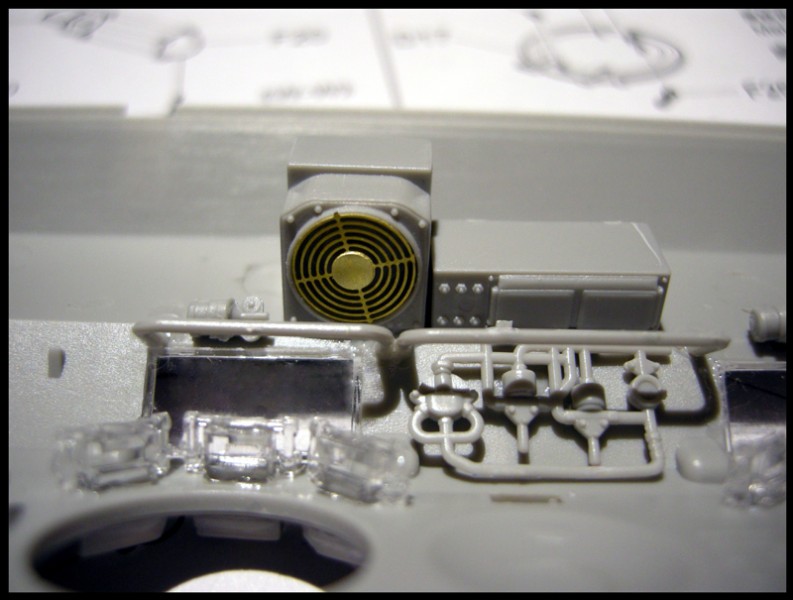
This next set of photos shows the only difference (other than the wheels) between 2S7 and the 2S7M.
Here are the air intakes for the 2S7 Pion.
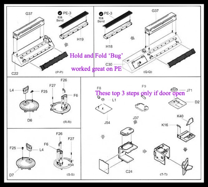
The rest of the page covering Step twenty-five- B~F, is straight forward, and of little difficulty. ( I used a 'Hold And Fold on the PE-3's ).
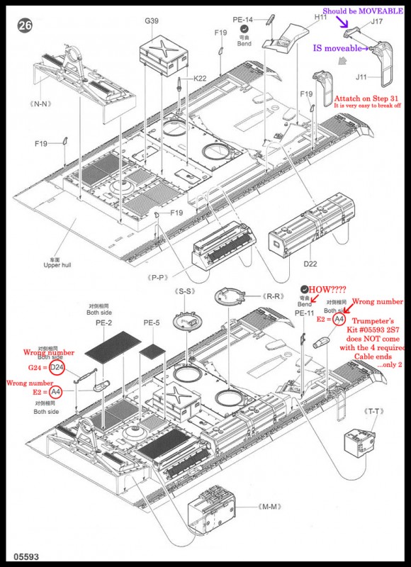
Step twenty-six:
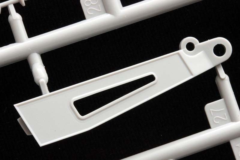
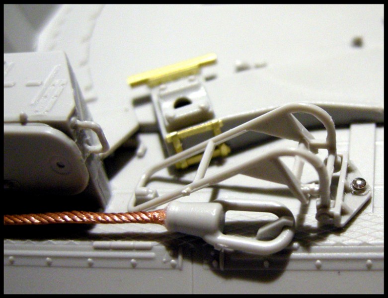
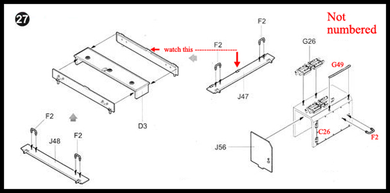
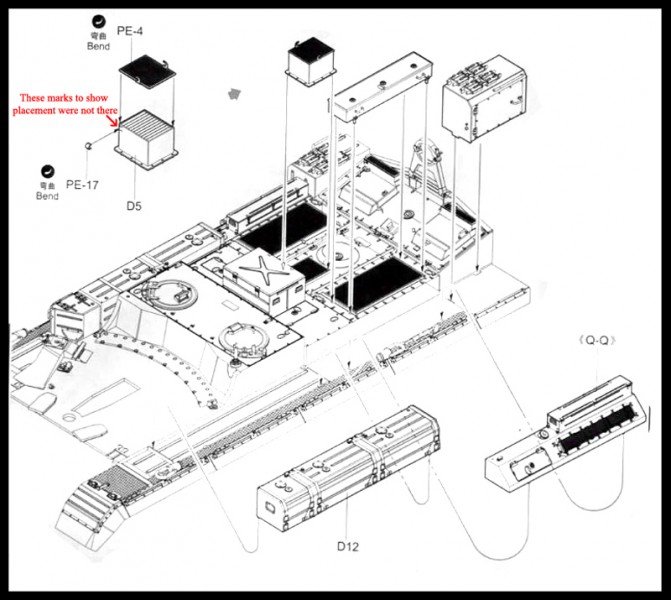
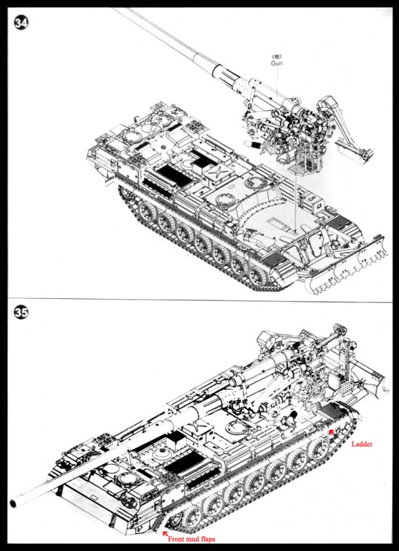
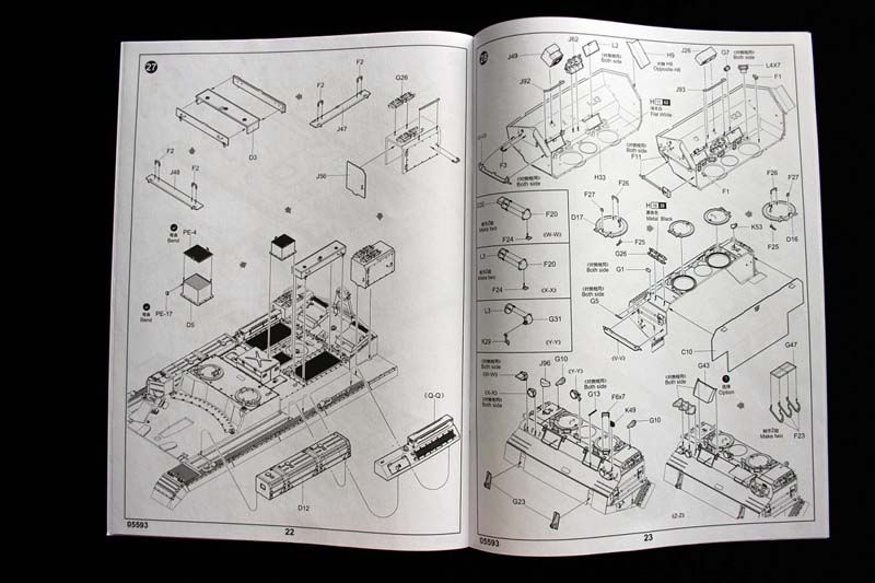
If I glued the ladder into the position shown in the instructions, it would break off before the tank was finished. I'd wait until step 35. Or you could do what I did; I pinned the ladder to the hull. This left it movable into the correct position for stowage. Frustratingly; I guessed wrong as how to fold PE-11 (again a missing piece of information). Step twenty-seven focuses on 5 storage boxes. D5 was a bit of a placement guess on the hull, but PE-17 was an entire guess, I could not see any marks for its placement.
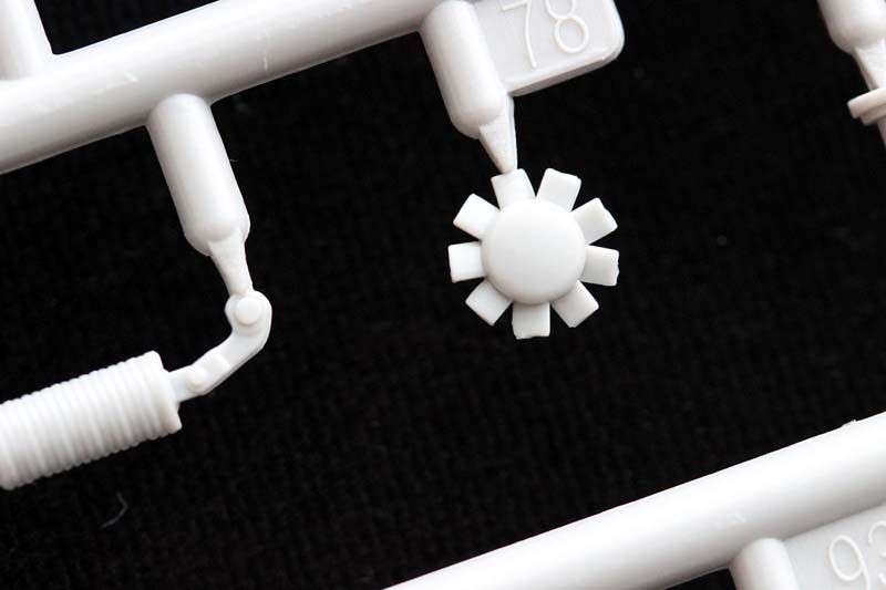
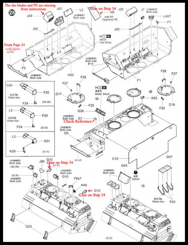
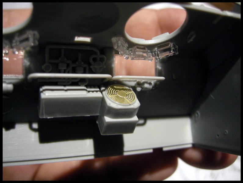
By step twenty-eight we go back to work on the inside of the drivers compartment. The instructions leave off the fan blades and fan PE placement....yes one could say any good modeler would be able to figure it out... But...I received the kit from Jim after an unboxing review...everything was fine when it got to me, but a few pieces were loose on the sprues, and a few pieces came off when I 'dish-racked' the sprues. One of the pieces that came off was the fan blades, so when I went to try and figure this subassembly...I missed the idea that there were blades until, in later steps removed the dish-rack and was shaking out the box.
Part J62 discombobulated me for a bit...but after review of a couple of different walk-arounds; this is the way this piece installs (in the: as pictured upside-down front cab "H").
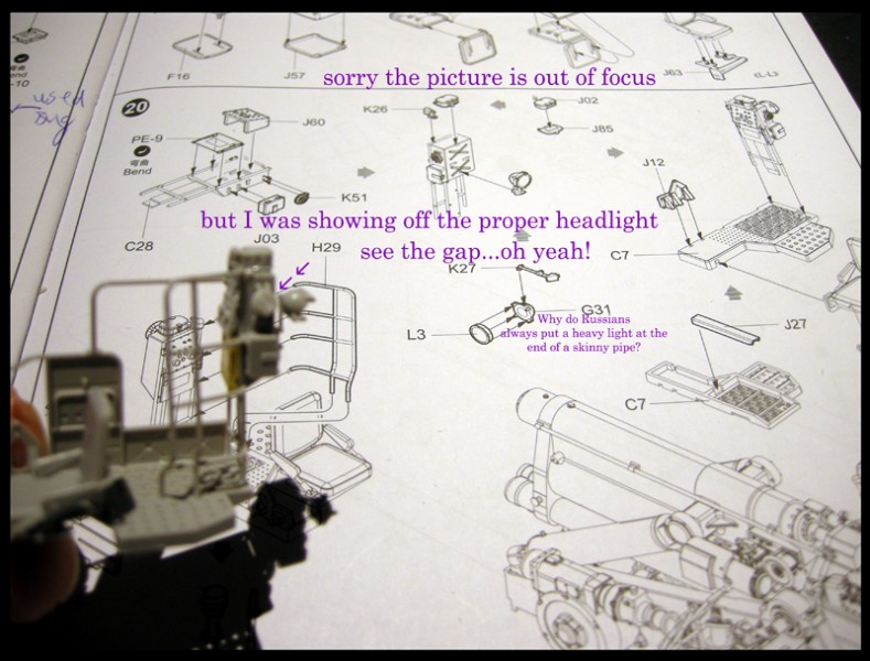
I've finally learned the difficulties with soviet head lights, and put the clear parts on.Then glue the connecters...LET DRY...for a day then try to cantilever them. The handles J92 and J93 can be a bit of a juggle until the glue dries. I used props to hold them in place. I didn't use the G9's from the next pages subassembly build as they broke on the sprues.
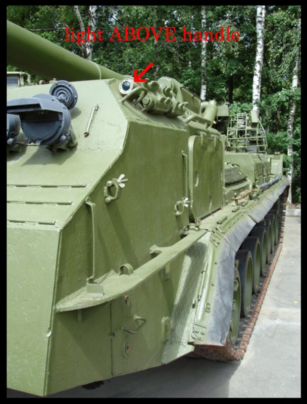
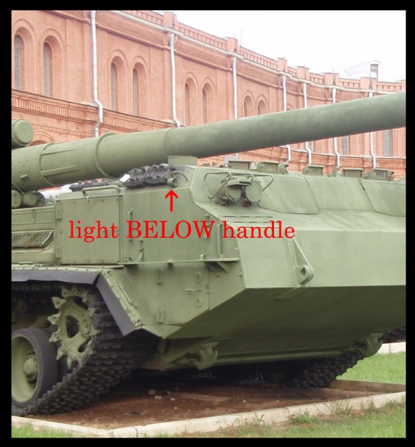
The G1 running lights are shown in the instructions to be placed above the handles (G5)...But I have seen reference photos that show their placement 'below the handles' ... I'm not sure why, maybe the difference is about the "M" variant, but the walk-around photos where I see light placement don't show the air filter covers.
Now to the F23&G47 build...its easier now one has had practice on the ammo carrier, and on the gunner's bird cage. I got very close, but as a speed build, I tried to place the light cage before it had completely dried - moving one out of alignment.
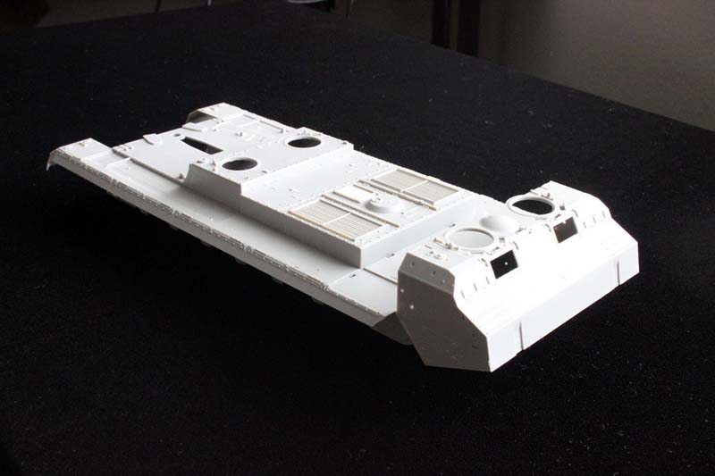
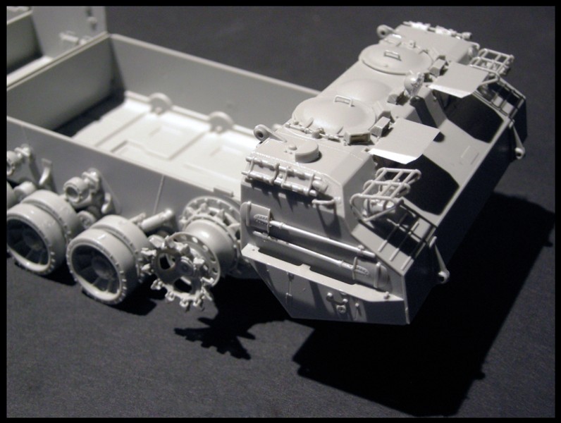
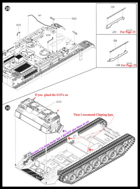
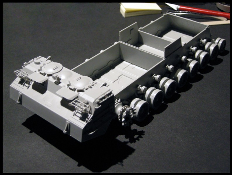
Step twenty-nine was easy; once I paid attention to the direction of the hull I was working on it is between these two steps I went back and dealt with the wheels, idlers, sprockets, and tracks.
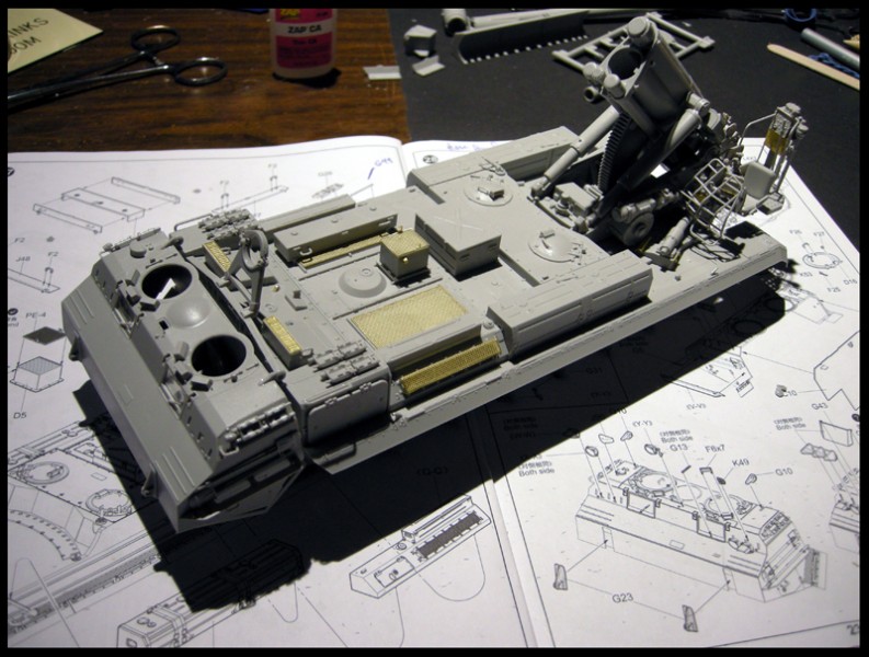
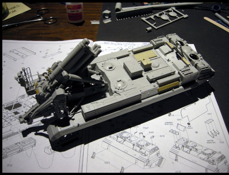
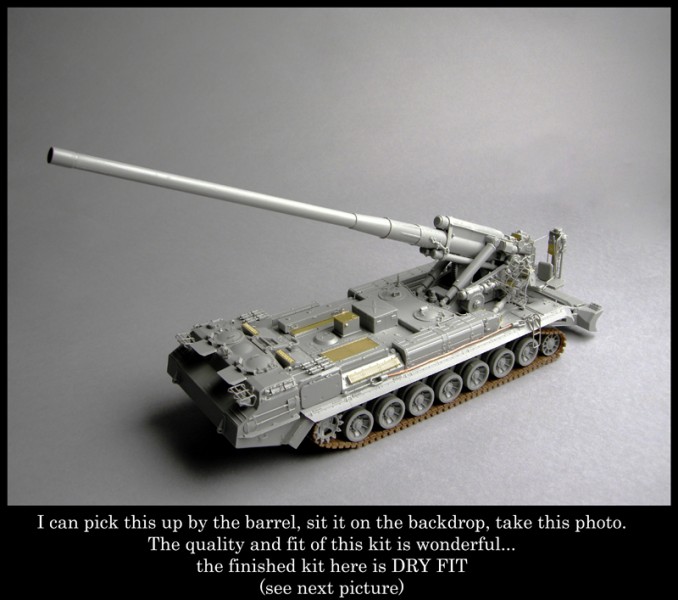
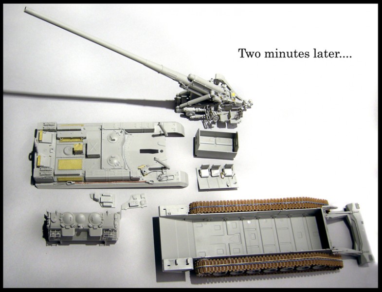
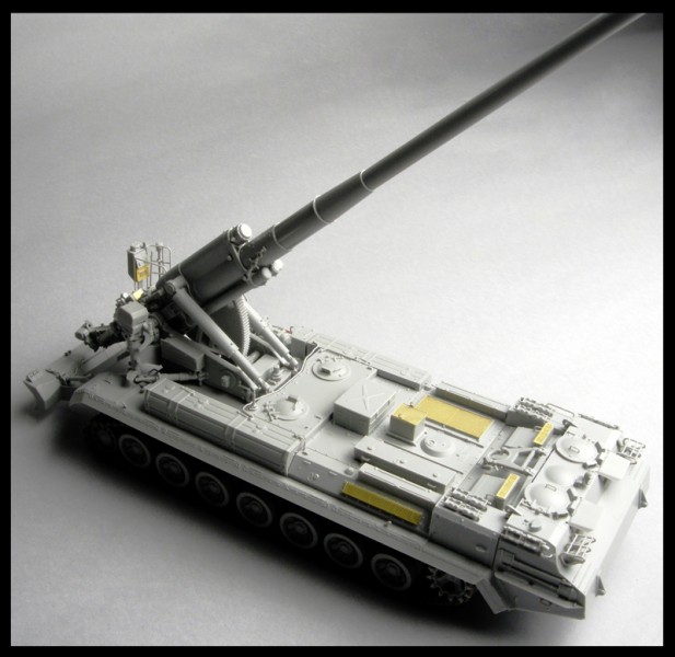
Step thirty: My lower hull now looks like the picture in Step30. This step shows how one could now glue the cab top on... I dry fit for the photos, because the kit fits together So well!
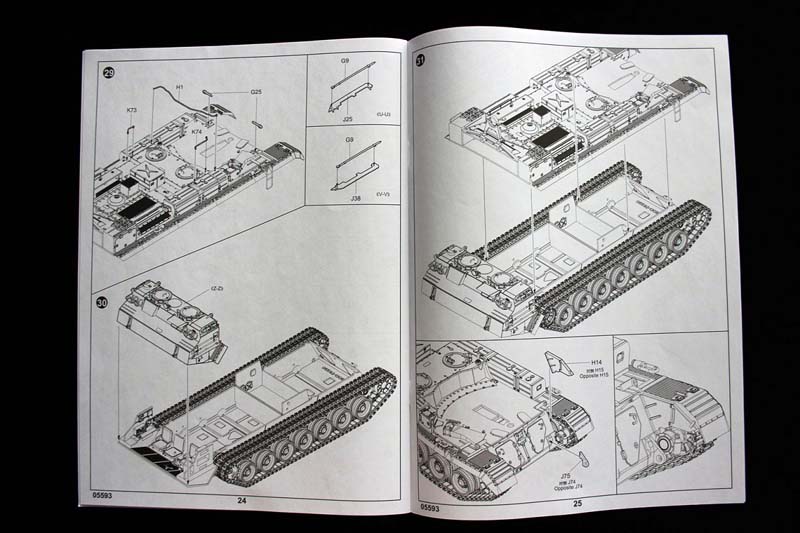
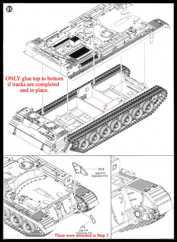
Step thirty-one:
This step shows how one could now glue the top of the tank to the hull... I dry fitted it (and of course had to place the gun on...just to see)...you can tell the cab is not fully on in one of the photos....LOL
Step thirtyone-B: I carefully (!) glued H14 and H15 to the lower hull so I could still take the kit apart later for painting. The parts J74 and J75 were already put on in Step 3.
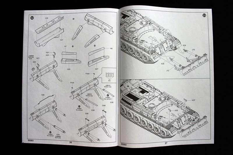
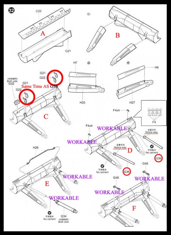
Step thirty-two: I was amazed at how well C20 and C21 went together. H26 was a bit fiddley that's why the instructions say "Notice Way" on the G36's
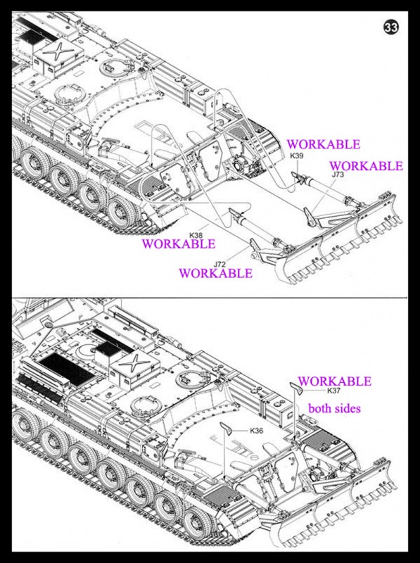
Step thirty-three is pretty straight forward.
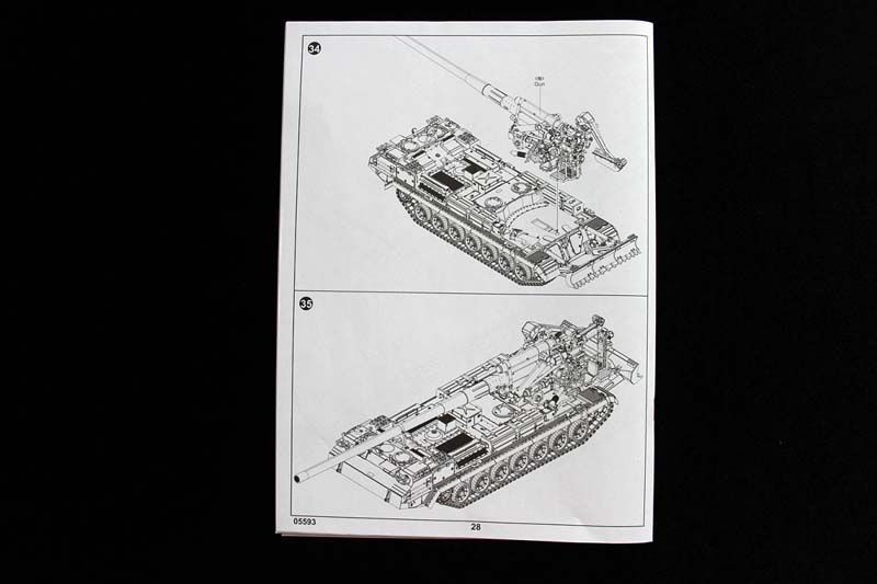
Step thirty-four: I dry fit the gun the arm...On the left side (J46 from Step 18) needs to be placed at the same time.
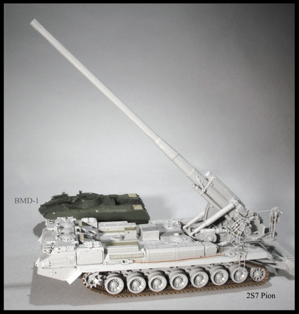
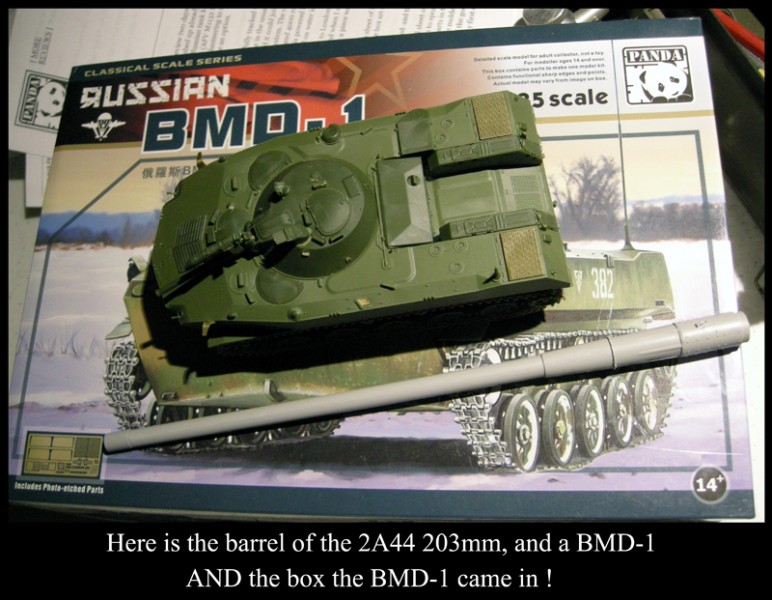
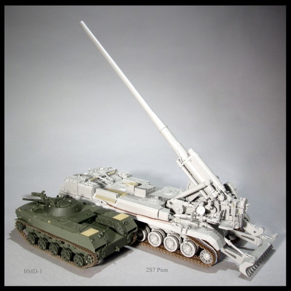
Step thirty-five: I guess this step is here to remind you to take a deep breath and realize what a heck of a build you've just done. The right side - I hot pinned the crane... but left all the other broken pieces as is. I'm using the BMD-1 kit I reviewed last year, as a Russian to Russian size comparison.
Conclusion
Even Jim in his video unboxing cemented about the quality of fit. I had only 11small issues of fit out of nearly 600 grey pieces; none were with large pieces. (I've labeled them on the instructions I posted.) I noticed and enjoyed the consistent type of sprue to part connectors. The consistency made it easier to pay attention to the part and its fit, rather than how difficult the next piece was going to be to cut off the sprue. One cannot stack the sprues in a box while working the kit; the pieces for each sub-assembly come from all the sprues ( unlike some kits that have all the mine plow pieces on just 2 sprues). I tried the 'Dish Rack' trick...It helped enormously! Although there are too many Very Delicate pieces on the sprues, I would recommend covering the rack 'ribs' with cardboard!
SUMMARY
Highs: As I'm sitting here trying to put words to how I feel about this model; the foremost feeling right now is that, I'm missing working on it. I guess I'll have to buy another and fancy it up a bit.Lows: The instructions are lacking as indicated by my build comments.Verdict: Its a perfect model for the person who can't help but wire up a 'funny-car' engine.
Our Thanks to Stevens International! This item was provided by them for the purpose of having it reviewed on this KitMaker Network site. If you would like your kit, book, or product reviewed, please contact us.
About C Johnsen (The_musings_of_NBNoG) FROM: OREGON, UNITED STATES
I started in,, maybe in 1965. I know my parents were relived to have me sit still for an hour. By '67 I was doublefisting, and gaining complexity. At 8; I became adept at tag swaping, to sustain the level of my habit. By '68 and '69: my challenge was Flyable Full Frame Balsa BiPlanes w/ doped paper ...
See photo #153 OR.....on my constructive feedback page....
.
LINK
.
Cheers
.
If I might add a personal note;
.
I enjoyed this build so much, I bought another one !
My pleasure... I was so totally focused on doing a speed build for everyone,,, that I didn't pay as much attention to the written word as I should have... I am very grateful to Jim, Darren and Berhidi, for all the slack they gave me concerning the final outcome of the article. After I had asked to do the build , Jim did an open box review, and I could hear the longing in his tenor. And not knowing any better I asked again to build the kit. Jim showed graciousness and kindness in sending it to me. I was the doufus that didn't realize the full requirements of a build "/review". ,,, but in the end we all ended up with a proper review.
All in all... Its a great Kit...and as I stated...I liked it so much I bought another to hold in reserve ..for the deep winter nights when I will need a freakin good challenge..... when I know I'll Love the outcome of; me v.s. plastic. ... (again)


Comments