The M3 half-track series was designed from the beginning as an armored personnel carrier. However, it proved to be quite adaptable and was used as a command vehicle, ambulance and the basis for several self-propelled gun variants. Over 12,000 M3s and more than 4200 M3A1s were produced which included more than 1300 converted from M3 75mm Gun Motor Carriages. Remanufacturing of M3 Half-Tracks and other self-propelled gun versions of the M3 during the war produced nearly 2600 additional M3A1s. The M3A2 was an attempt to combine the features of the M2 and M3 series by allowing the configuration of the personnel compartment to be changed based on what the vehicle was used for. Five Autocar produced M3s were converted into M3A2s by International Harvester with no series production taking place.
While many of the half-tracks were quickly retired after World War II, some continued to see service with the U.S. Army well into the 1950s. Many more were exported and used by armies throughout the world into the 1980s and 90s.
The kit
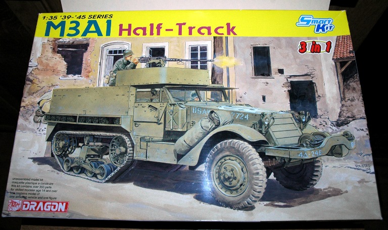
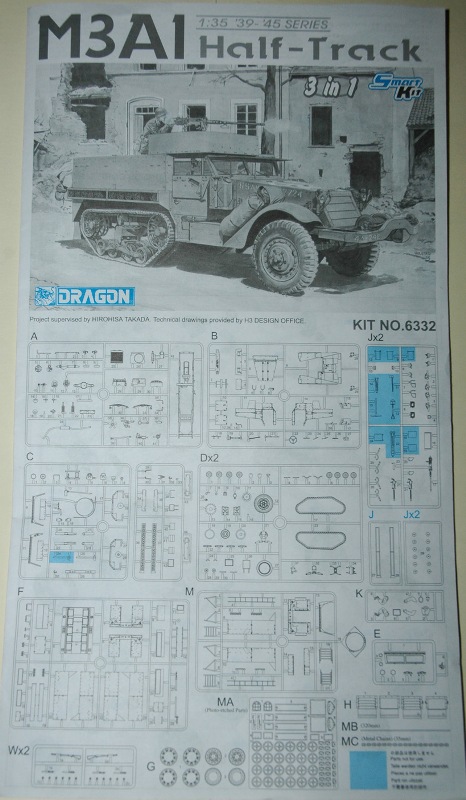
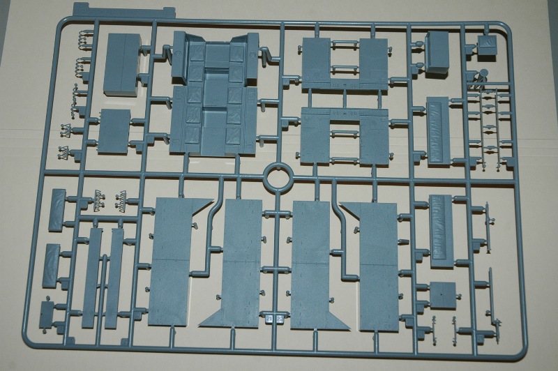
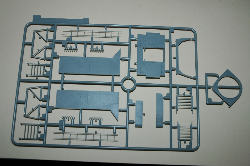
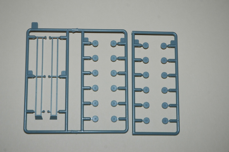
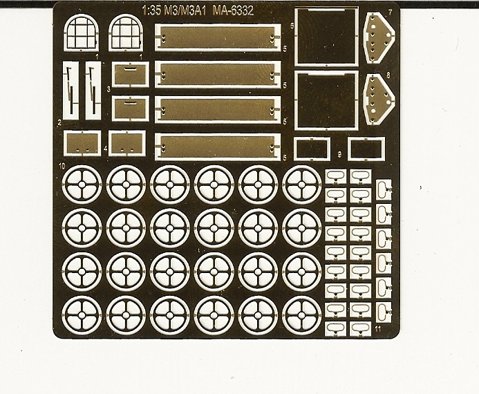
In the second half of 2006, Dragon released the first of their new U.S. Half-Tracks, the M2A1. When it was released, Dragon also showed test shots of the M3 Half-Track. Now, just less than three years later Dragon brings us the long awaited M3A1 Half-Track 3 in 1 Smart Kit! Comprising of 433 plastic parts attached to 17 grey and 1 clear plastic sprues, Dragon gives the modeler quite a bit to work with. Also included is a 66-piece PE fret, a small length of thread and a small length of chain. Two decal sheets and a 10-page instruction booklet round out the kit.
The quality of molding is quite good. My sample had no flash on any parts, only the usual mold seams to scrape or sand off. There are quite a few injector tabs to remove and some of them can leave nasty scars on parts if not carefully removed. While there are some injector pin marks to fill in, most of the marks are in areas that will not show after the kit is assembled.
Construction
I had originally started this review as an in box preview. However, I decided to complete several assemblies to give readers a better idea of what to expect from the kit. So, here we go!
Step 1
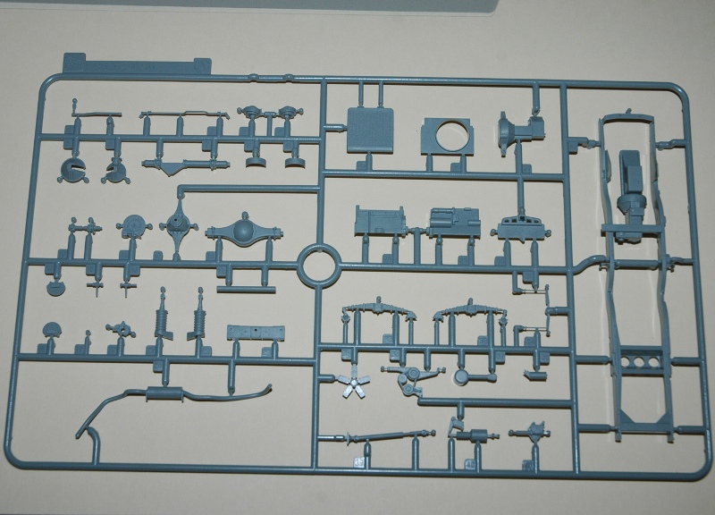
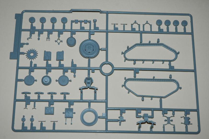
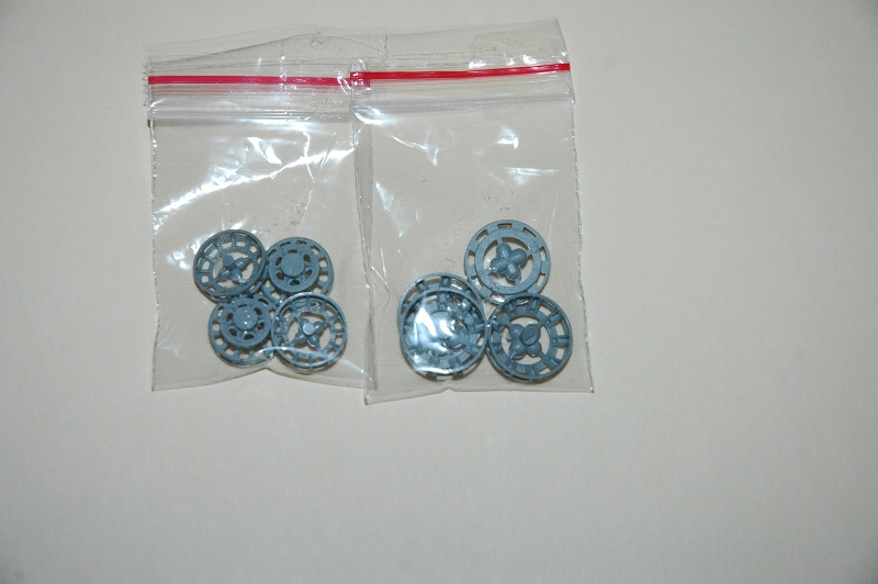
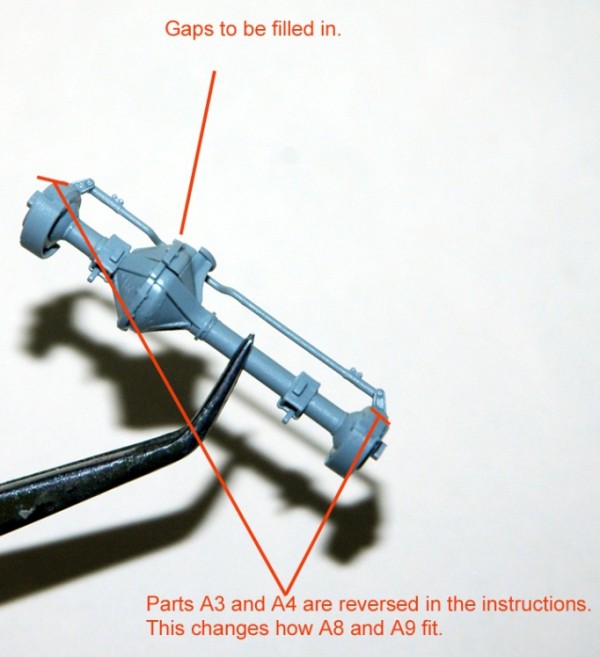
This step actually consists of 8 different sub-assemblies. A covers the engine. Detail on the engine is basic and it assembles without any problems. B covers the front axle and differential. When assembled, Parts A5/A6 end up with some gaps that need to be filled. Parts A3/A4 are the steering knuckles. The instructions show A3 be fixed to the left side of the axle and A4 on the right. It turns out that it should be the opposite. This in turn results in the steering knuckle guards, Parts A8/A9 also changing position. C is the sub-assembly for the radiator and radiator shroud. The radiator is detailed only on the front side so if you want to display the engine compartment open, youll need to add detail to the back of it. D covers the rear differential while E covers the drive sprockets. The sprocket flanges, Parts G1, have injector pins in the center of them. Carefully, remove the pins or youll end up with some broken parts. F covers the front tires. The tires have the non-directional tread and still have the sidewall bulge. Im not going to get into it in this review but there are plenty of aftermarket wheel sets available if you dont like the kit ones. G covers the idler flange assemblies while H covers the assembly of the front wheel hubs.
Step 2
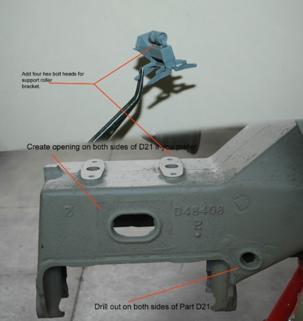
This step has the modeler assemble the rear bogie units. A little bit more confusion happens with the instructions here as a portion of the bogie frame bracket that attaches directly to the frame, Part D21, is referred to as D21 and D32. The other portion of the bracket is also referred to as D21 and D32. So, which one is which? D21 attaches directly to the frame while D32 attaches to D21. Overall, the bogies are nicely done and relatively easy to assemble. The previously mentioned bogie frame brackets should have a small hole drilled on either side of them. You can also add a larger, oval shaped hole if you wish. Make sure the bogie outer frames, Parts D22, have the flat side on the bottom when attaching the bogie lower rollers to them. The track support roller bracket, D34, can have 4 hex-bolt heads added to it should one desire to.
Step3
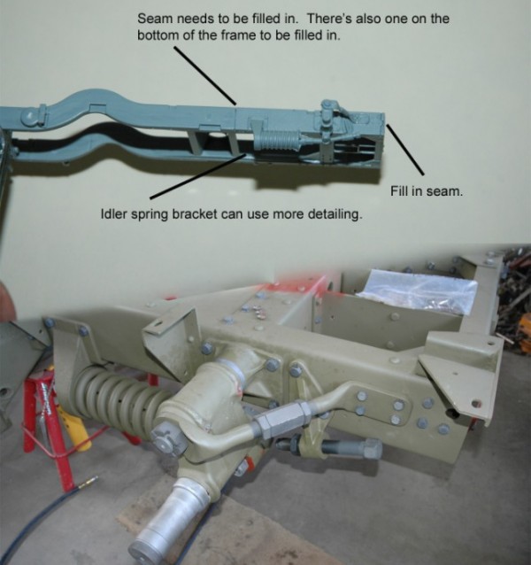
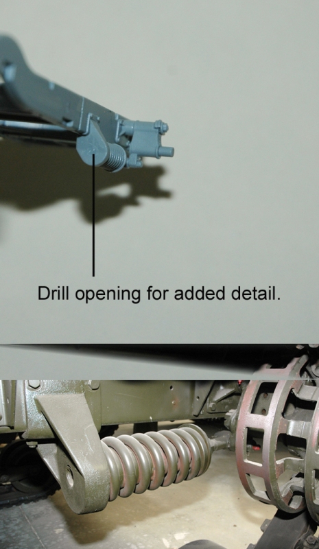
The frame, transmission and rear idler brackets are assembled in this step. The idler wheel brackets went through an evolutionary process on the M2/M3 series. Early vehicles were produced with a fixed idler that was adjustable. However, it proved not capable of handling the stresses of cross-country driving and was soon replaced by a single-coil idler spring. This in turn was replaced by a double coil idler spring. When Dragon released the M2, they took some flak for only including the double coil spring option. Theyve somewhat addressed the issue here by providing parts to build the kit without the idler spring. When adding the parts for either type of idler set up to the frame, youll need to fill in the seams caused by joining Parts A21/A22 or C43/C44 to the frame. Strangely enough, the non-idler spring frame parts, C43/C44 still have the mounting plate for the idler post brace, Part C29/C30, molded onto them. The modeler will need to remove this plate from the kit parts. The double coil spring assembly can use some added detail.
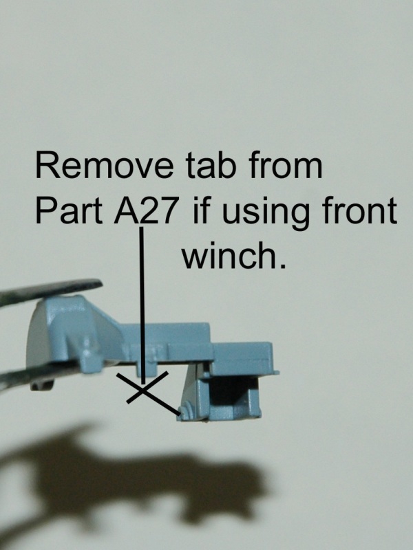
The upper part of the transmission, A27, has a tab that needs to be removed if modeling a half-track with a winch. Other chassis parts are added here as well.
Step 4
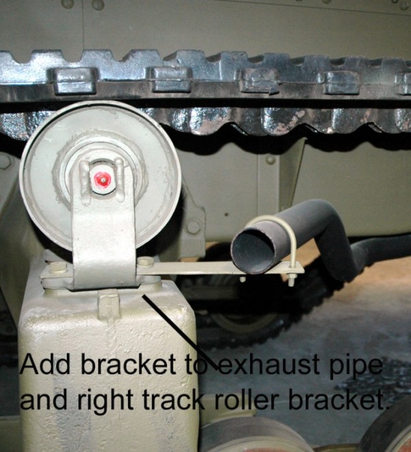
The previous assemblies for the radiator, rear bogies, and front differential are added to the frame. Theres a special call out for the winch propeller shaft. While it specifically says its for the M3A1, you can still use it for an M3 if your references indicate as such. The muffler is added in this step as well. A small bracket to support the exhaust pipe needs to be fabricated and attached to the pipe and the right hand bogie assembly.
Step 5
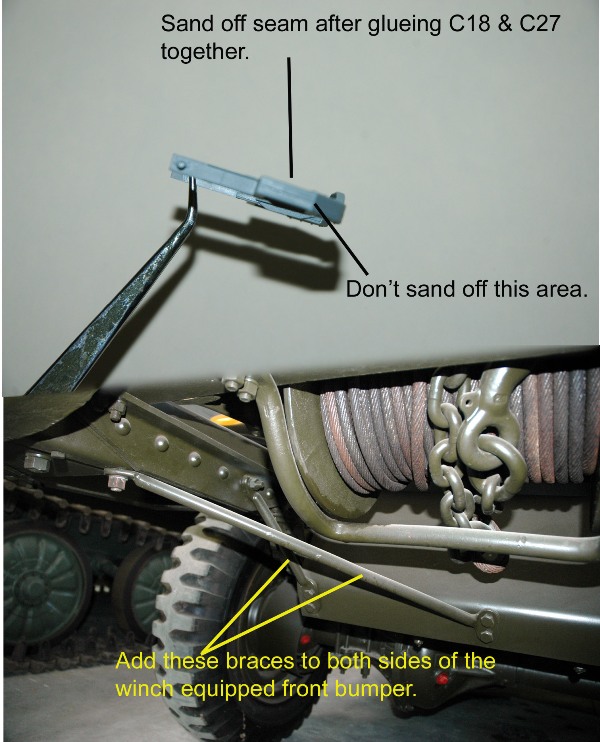
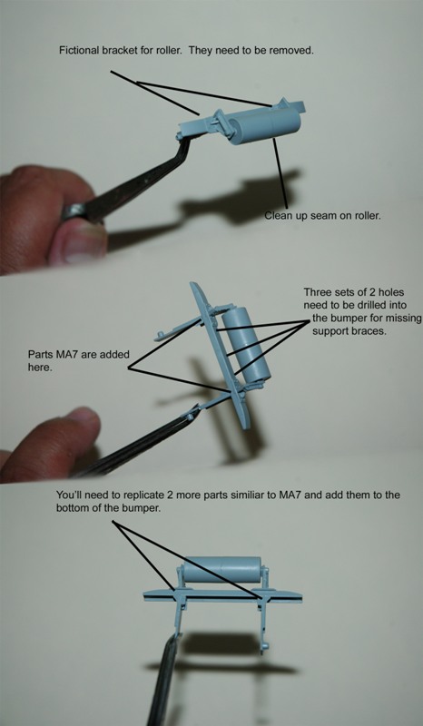
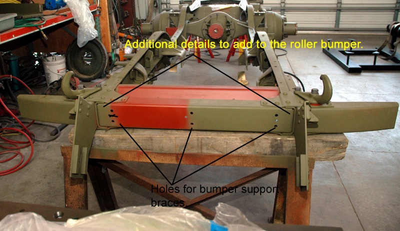
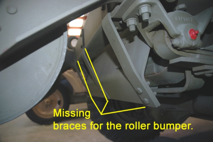
In Step 5, the modeler is given the choice of using either the winch equipped front bumper or the unditching roller version. When assembled, the front winch bumper has a seam that needs to be taken care of. Dragon fails to provide the 2 pairs of reinforcing braces that are bolted to the bottom of the bumper and the armor plate below the radiator.
There are some accuracy problems with the unditching roller bumper. To put it frankly, it appears to be fictional. Nothing in the tech manual, numerous period photos and photos of display vehicles that I could find support this version of the bumper. The roller support brackets, Parts C15/C16, do not attach to the front of the bumper like on the kit. Instead, they are part of extensions that bolt directly to the frame. The bumper itself is three pieces with four gussets that hold all of the pieces together. If you want it to look somewhat accurate, youll need to remove the two molded on plates from C26. Then youll need to make two more gussets that look like Parts MA7/MA8. These parts will go on the bottom of the bumper. Some scribing around the outer edges of C15/C16 will help give the illusion of a three-piece bumper. Finally, three bracing straps will need to be attached to the bumper and armor plate below the radiator.
The tracks, idlers and drive sprockets are also added in this step.
Step 6
The front wheels and wheel hubs are added here.
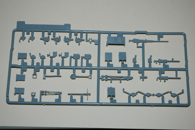
Step 7
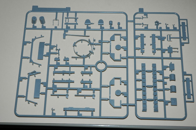
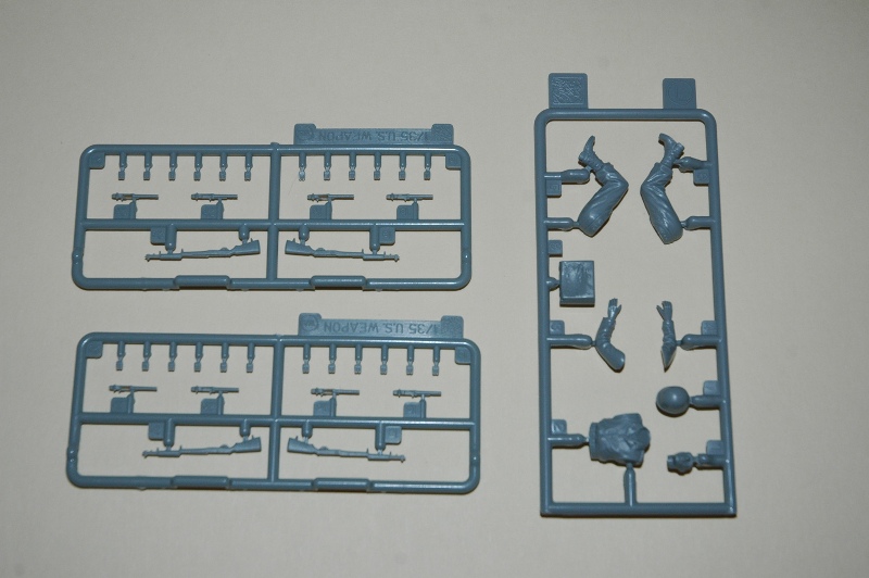
There are five sub-assemblies in this step. J covers the .50 caliber M2 machine gun. K covers the .30 caliber M1919A4 machine gun. L has you assemble the M1 Garand rifles. M covers the instrument panel and steering column. The instrument panel provided is appropriate for the M3 and M3A1. However, although produced by Autocar, the M3A2 pilot used the International Harvester style instrument panel, which is quite different than the M3/M3A1 type. N covers the water/gas cans.
Step 8
The driver figure is assembled in this step.
Step 9
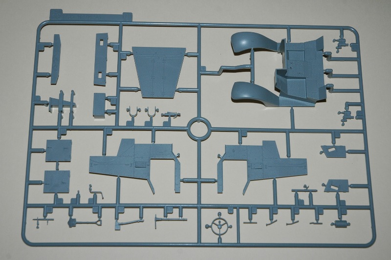
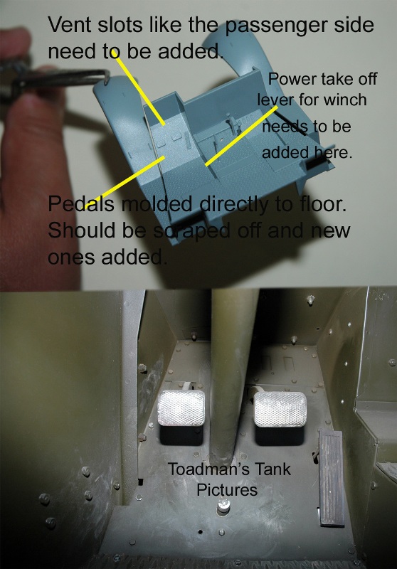
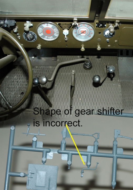
The drivers compartment is assembled in this step. Overall, this area is complete. The treadplate pattern looks good and is in the correct places. The drivers pedals are molded directly to the floor and look really poor. Scrape them off and add new ones from styrene and wire for a better effect. The gear shifter, B13, is poorly shaped and should be replaced. If youre building a winch-equipped vehicle, youll need to add the power take off shift lever. This goes next to the drivers right leg and is not included with the kit. Part B27 is the generator filter. The tech manual indicates that this item is used in M3s produced up until early 1943. Therefore, new production M3A1s wouldnt have it but M3s remanufactured into M3A1s possibly could. You make the call!
Step 10
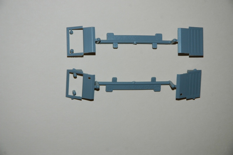
The armor for the hood and drivers compartment are added here. Part B11 and B14 have an injector pin mark that needs to be filled as it will show when attached to the assembly from Step 9. Also, theres an opening from the water/gas can mounts that needs to be filled in. The water/gas can mounting bracket is molded directly to the side armor. The real thing is actually a thin metal bracket that is hollow behind it. Early production M3s did not have this mount so if you want to make one of these tracks, youll have to cut the brackets off and hopefully not cause too much damage to the armor and bolt detail.
Step 11
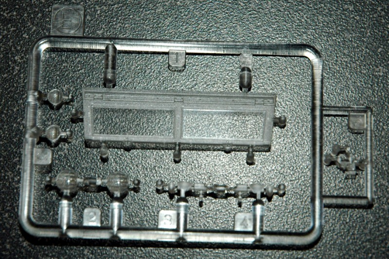
The windscreen and hood are added here.
Before I get to Step 12, I need to warn you that this is where some of the real confusion and surprise is. First off, when the M2 was released, Dragon received a fair amount of flak for having rivets on the armor plates instead of dome shaped screw heads that the real half-tracks were assembled with. Modelers figured if Tamiya could do it 30 plus years ago, why couldnt Dragon? Starting with the M16 Gun Motor Carriage kit, Dragon added screw heads to the rear plate. Then, with the M3 75mm Gun Motor Carriage, screw heads were added to all of the plates. To make a long story short, Dragon must have got lost somewhere with this kit as it has the same rivets as seen in the M2 kit. I guess after the original tooling was cut, Dragon didnt feel that it was cost effective to make changes. Thats a shame.
In any case, from now until the rest of the kit is assembled, the modeler needs to pay close attention to the callouts in each step of the instructions to make sure they are using the correct parts for the vehicle they are modelling. There are three separate sequences here, one for each variant. Hopefully, I dont confuse you.
Step 12 and Step 13
M3:
These cover the rear armor and lower body supports. Make sure you drill out the correct hole for the machine gun pedestal.
This step also applies to the M3A1 on the next page while Step 13 also applies to the M3A2 two pages later.
M3A2:
Four sub-assemblies are in this step. Q covers the armored ring mount. Parts M14 and M15 have injector pin marks to fill. R and S are for the headlights while T covers the .30 caliber M1919A4 machine gun.
Step 14
M3 or M3A1:
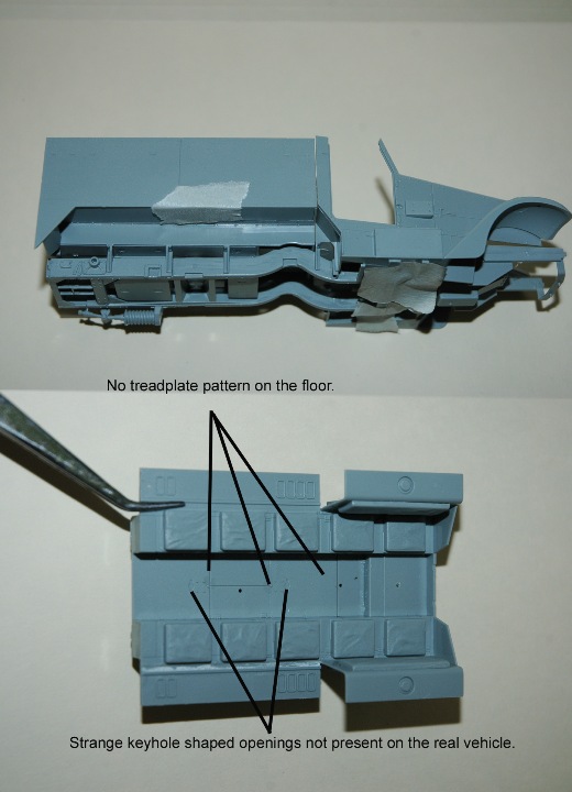
This covers the interior of the passenger compartment and has you adding the seat backrests and other parts. Part F6 that has the floor, passenger seats and fuel tanks molded to it is missing the treadplate pattern on the floor. This is quite wrong and will need to be added. Its strange that Dragon didnt include it as the M2 kit has it included. Also, there are two keyhole shaped openings in the floor. They dont appear in any period photos, tech manual pics or display vehicles. Maybe they belong under the missing treadplate? Also remember that the machine gun pedestal, Part F12, is for the M3, not the M3A1.
M3A1:
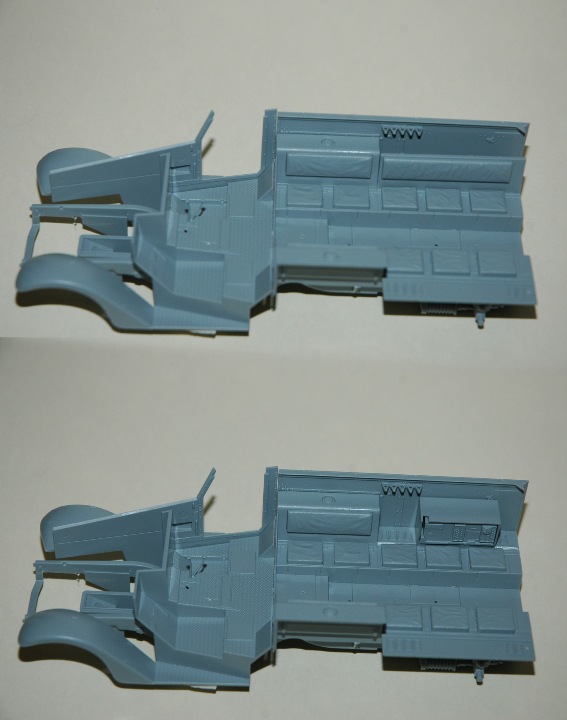
Another Step 14 is shown on the next page for the M3A1. It has you add the radio, antenna mounts and support brace for the armored ring mount along with other details.
M3A2:
Similar to the Step 14s for the other variants.
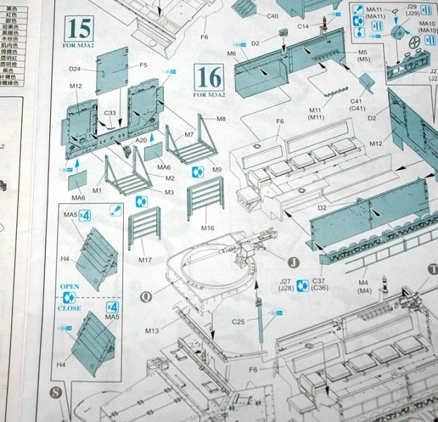
Step 15
M3 or M3A1:
The passenger compartment armor is added here along with a few other details. The rifle racks, F17 and F3 can be carefully sanded down for a more scale look.
M3A1:
Three sub-assemblies for the winch and headlights.
M3A2:
The rear armor is assembled here along with rear luggage racks. These racks are not M3A2 specific and were retrofitted to M3s and M3A1s. Check your references.
Step 16
M3:
The headlights are added here. Photoetch cages are provided but thin plastic rod might look better.
M3A1:
Like the M3, the passenger compartment armor is added here along with mine racks and the machine gun ring mount. Parts C10 and C12 have some injector pin marks to fill. Regarding the mine racks, Dragon took some heat with the M2 by molding the mines directly to the racks. They listened and in this kit provided separate mines to fit into the racks along with the original parts from the M2. Good job, Dragon!
M3A2:
Similar to the previous Step 16s. PE stowage racks are added here. Please Dragon, they are stowage racks, not ladders as you call them on the side of the box. Additional detailing can be added to the racks. Also, like the rear luggage racks, these were retrofitted to M3A1s.
Step 17
Final assembly of each variant on three different pages.
As you can see, the instructions can be very confusing.
Painting and Markings
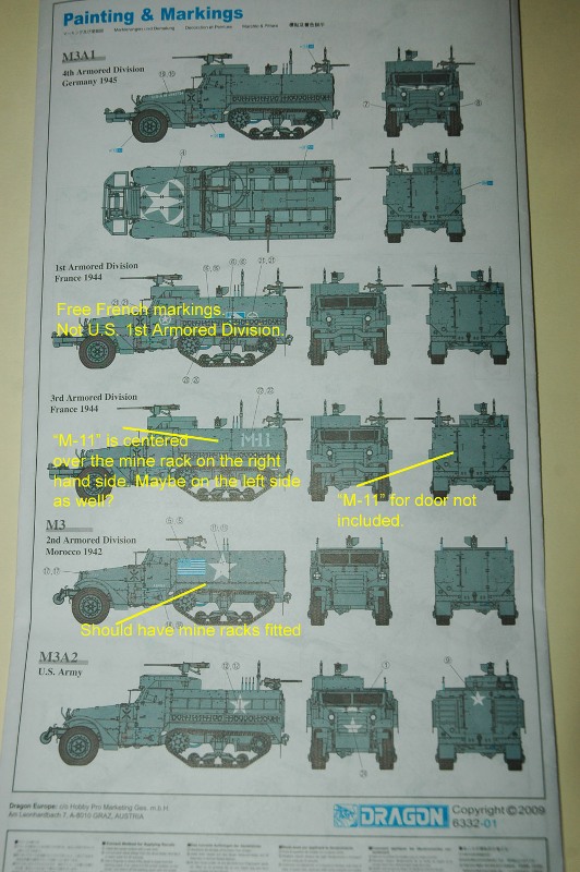
All vehicles that markings are provided for are in olive drab. The first vehicle is an M3A1 of the U.S. 4th Armored Div. in Germany, 1945. I couldnt find any reference pics to compare it to.
The next vehicle is for the 1st Armored Div. in France, 1944. Keep in mind that it is for the Free French 1st Armored Div, not the U.S. one.
The third M3A1 belongs to the U.S. 3rd Armored Div, France 1944. A photo in the Concord book listed below shows the right hand side M-11 centered over the mine rack. Its possible that this could apply to the left side as well. Also, an M-11 marking should be on the rear door but is not included in the kit markings.
The M3 belongs to the U.S. 2nd Armored Div. in Morocco during 1942. This vehicle is supposed to have mine racks. The kit instructions do not show this but the same Concord book mentioned above shows this vehicle mounting them.
Finally, since the M3A2 never went into production, mark it however you want. However, photos of the pilot vehicle in the Hunnicutt book show no star but a very light colored U.S.A. registration number which actually may be in blue.
The decals look good and the print is in register. A nice second sheet featuring numerous letters and numbers for bumper codes is included and is a real nice touch.
Conclusion
This is quite a good kit that has several areas that prevent it from being a great one! On the plus side, the numerous variations and subject matter along with addition of the separate mines and no idler spring option are great. There are plenty of spare parts to use for other half-track kits that you may have in your stash. However, the minuses include the missing of important details such as the passenger compartment treadplate, the reverting back to rivets for the armor plate and the fictional unditching roller. While these things arent unfixable, they really shouldnt have to be fixed in a $50.00 kit. When building this kit, the modeler will need to pay real close attention to the instructions and/or have a good set of references available.
Recommended.
References:
Franz, Michael, editor: U.S. WW II Half-Track Cars M2, M2A1, M9A1, and Personnel Carriers M3, M3A1, M5, M5A1; Tankograd TM Series #6009, 2007
Zaloga, Steven; U.S. Half-Tracks in Combat 1941-1945; Concord Publications, 1999
U.S. Army; TM 9-710 White, Autocar, and Diamond T Half-Tracks; February 1944
My own personal photo collection.
SUMMARY
Highs: Great subject matter. New addition of separate mines and early non-idler spring version included. Nice decals. Lows: No treadplate for the passenger compartment, fictional unditching roller bumper and rivets. Instructions can be quite confusing.Verdict: Recommend, but make sure you have some decent references available.
Our Thanks to Dragon USA! This item was provided by them for the purpose of having it reviewed on this KitMaker Network site. If you would like your kit, book, or product reviewed, please contact us.
About Chris Hughes (toadman1) FROM: CALIFORNIA, UNITED STATES
I've been building models off and on for the past 35 years. I currently spend more time photographing the real thing more than building but I'm okay with that.


Comments