INTRODUCTION
For years and years the ability to build a modern Canadian armoured vehicle out of the box in any form eluded modellers. Over the past several years model producers have begun what was once impossible. Trumpeter in particular has taken the proverbial injection molded bull by the horns and has produced the LAV III, the LAV III TUA, the AVGP Cougar, and now the AVGP Grizzly. Rumors have it that the AVGP Husky and the late version Grizzly will also be produced by Trumpeter. Pre-release build mock up images of the Grizzly showed a late version of the vehicle, however, this kit is touted as the early version. The issue of early, mid, and late versions can be confusing to modellers but hopefully this review will clarify exactly what the Trumpeter Grizzly kit will build into. Before I begin the review a bit of historical background into the Grizzly would be appropriate. The Grizzly is a wheeled armoured personal carrier designed by MOWAG for Canada and based on the 6X6 Piranha I hull. Between 1979 and 1982 the AVGP (Armoured Vehicle General Purpose) series was built in Canada. The AVGP series of vehicles were purchased in order to provide the Canadian Army with a common wheeled armoured vehicle series that could fulfill a general combat capability requirement.The Grizzly has a crew of three consisting of a driver, a commander, and a gunner. An Infantry Section of six to eight could be carried in the back. Pistol/Rifle ports were fitted to the hull sides and rear doors. The Cadillac-Gage One Meter Turret originally designed for the U.S. V-150 was equipped with two banks of grenade dischargers, a .50 Cal HMG, and a 7.62 mm GPMG. The Grizzly, like the other vehicles in the AVGP series, was amphibious by way of a marine drive system consisting of propellers, rudders, and a trim vane. The Grizzly was both loved and hated by the Infantry. It was fast and easy to maintain compared to tracked APCs but it was not favorable to be inside while it bounced cross country. The two rear doors inhibited fast dismounts when compared to a ramp. The non-stabilized turret provided the dismounted Infantry with additional firepower but the vehicle was not designed as an MICV where the crew would fight from inside or fire the turret guns on the move with any sense of accuracy. The Grizzly was used in Canada as well as during deployments between the 1980s to the early 2000s to Northern Europe, Africa, the Middle East, the Mediterranean, and the Balkans. Not too shabby for a lightly armoured, machine gun armed, wheeled vehicle.
WHAT ARE YOU BUILDING?
Over the years of service the Grizzly had a number of upgrades. I will provide a basic overview of the external modifications so you will understand what exactly you are building with the kit parts.
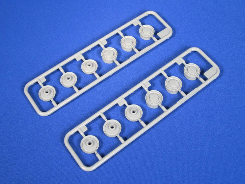
Early Version - When the Grizzly first entered service in 1979 it did not have guards for the propellers or rudders. It did not mount wire cutters on the hull or turret. The turret had an external AA ring sight mounted on a bracket on the original M28C sight. A vision block was also mounted on the turret in front of the M28C sight housing. During the timeline of the early version the guards for the propellers and rudders were added around 1984/1985. The hull and turret wire cutters were added and dual shocks were added on either side of the front struts. The wheel hubs had a visible protruding center bolt. As you will come to see the Trumpeter kit is not the early version and it is impossible to build the early version from the kits parts without scratch building all of the early turret modifications.
Mid Version - The Grizzly went through a turret upgrade in 1993/1994. The major external change shows the small M28C sight replaced by the larger M36E1 sight. The upgrade required fitting a larger sight housing to the turret. As a result of the new sight the wire cutter and the front center vision block were removed from the turret. With the turret upgrade the old C5 GPMG was replaced by the trustworthy C6 GPMG next to the .50 Cal HMG. The wheel hub center bolt was replaced with a recessed window to check fluids. If the kit is built without using the unnecessary and incorrect parts that Trumpeter included in the kit you will build this version.
Late Version - The Grizzly was upgraded for the final time in 1999. The upgrade does not include operational upgrades that occurred in Bosnia or Kosovo with add-on armour packages. The upgrade included the removal of the marine drive system. The marine drive system was replaced by stowage boxes on each side of the rear hull and the removal of the trim vane. The original tires were replaced by the larger XML tires. A standardized application of anti-slip surface was applied to the upper hull and larger mirrors and brackets were mounted. On the rear hull a hinged door locking mechanism was also fitted. Some late version Grizzlies also had the turret wire cutters re-mounted. Over time upgraded communications boxes were also added to the left hull side. While some of these late version parts are included in the kit it cannot be built into a later version simply from using the kit parts.
KIT CONTENTS
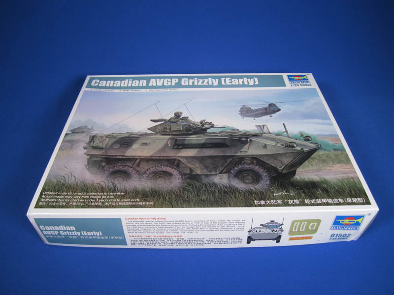
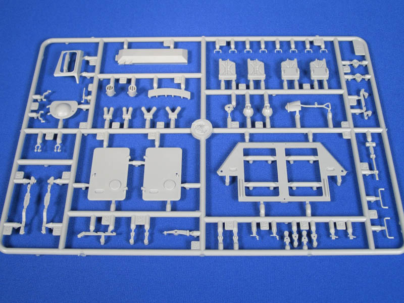
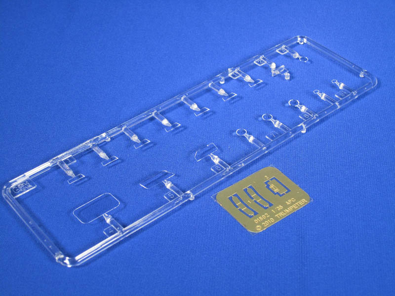
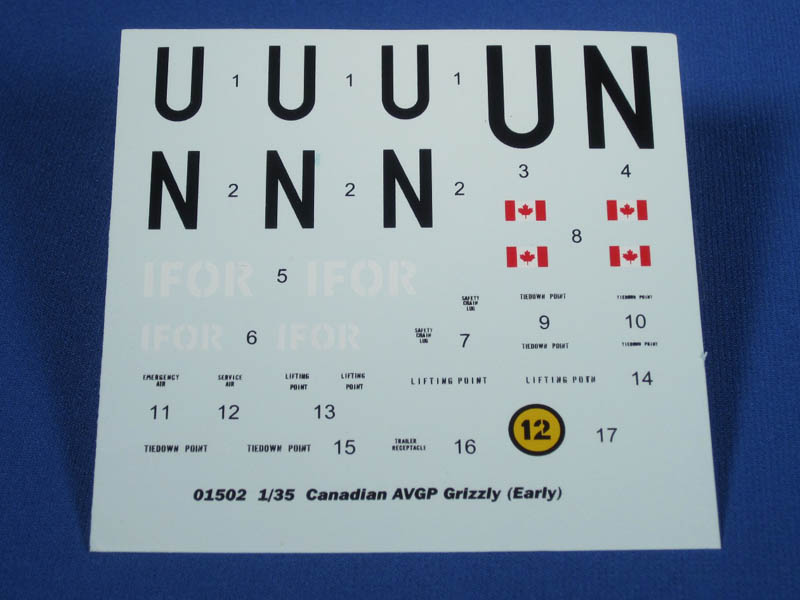
Ok, so what do we have in the kit now that you know what you are building? The kit has 220 parts. This includes the plastic sprues, a sprue of clear parts, a decal sheet, and a small fret of photo etched parts.The kit comes packaged in a standard two piece box. The parts are molded in grey with the sprues heat sealed in plastic. Some of the small fragile parts are additionally wrapped in thin foam. Overall the parts quality is pretty good. The Trumpeter site touts using slide molding for the upper and lower hulls. The detail on the parts is crisp and Trumpeter has done a pretty good job of either eliminating or hiding injection pin marks. The exception is the inside of the propeller guards that have a large injection pin mark on the inside of each part. The clear parts are included for all of the turret vision blocks, the headlights, the spot light, the drivers windscreen, and the turret sight. There are two clear parts marked as "not used" that appear to be for taillight lenses. The turret vision blocks will need a transparent green applied to make them more accurate when fitted.The three small photo etched parts are for the front turn signal guards and the turret sight cover. These parts are a nice addition.The decals are sealed in plastic to avoid damage when handling prior to attaching them. They have great colours, crisp edges, and no register issues.
INSTRUCTIONS
The instructions are included in a booklet form with essentially ten pages of assembly instructions provided in the standard drawn subassembly process. Modellers may look to alter the sequence so the upper and lower hulls are attached together and then the small details added instead of adding details to the lower hull and then to the upper hull and then attaching the two together.Moving to the turret assembly modellers will find this is challenging as Trumpeter has failed to include instructions as to how to actually assemble all the turret parts. This appears to be a mistake as two exactly identical drawings of the turret being placed on the complete hull are provided. There are instructions included to assemble the top of the turret and the gun mount but this does not assist in the actual part placement for the remainder of the turret. In order to assist modellers I have come up with a sequence that should point you in the right direction for properly assembling the turret. (Trumpeter, feel free to send me a royalty!)
1. Assemble the dual gun mount as per step 12.
2. Attach part H11 (turret left side) to part H35 (turret bottom).
3. Attach part H10 (turret right side) to part H35.
4. Attach part H18 (quarter circle front lower turret) to the front of part H35. The small lugs on H18 fit into the grooves on inside front lower edge of H35.
5. Fit the gun mount from step 12 into the trunnions on part H35. Do not glue if you want the guns to elevate.
6. Attach part H28 (turret top) to the parts H10 and H11 ensuring you do not put glue on the gun mount.
7. Attach parts H30 (lifting eye) to the front of H28 into the holes provided.
8. Attach part GP3 (spotlight lens) on part H19 (spotlight). You may want to alter this sequence until after painting.
9. Attach part H19 into part H23 (spotlight guard).
10. Attach H23 onto the top of the .50 Caliber machine gun side of the gun mount assembly. Note the alignment hole on the gun mount for the spotlight guard.
11. Attach parts H17 (grenade box) to the right and left sides of the turret.
12. Note
test fit the parts for the grenade discharger assemblies
..Attach part H7 (grenade discharger top left) to part H9 (grenade discharger bottom left)
13. Attach left grenade discharger bank (H7and H9) to the left side of the turret.
14. Attach part H6 (grenade discharger top right) to part H8 (grenade discharger bottom right).
15. Attach right grenade discharger bank (H6 and H8) to the left side of the turret.
16. Assemble the upper turret assembly as per step 13.
17. Attach the upper turret assembly to the lower turret assembly as per step 14.
PAINTING
Also included in the kit is a colour double sided painting and decal guide. Note that on both sides of the painting guide there are also small Canadian Forces Registration plates that need to be cut out.For those that know me I do my research when I review a kit or build a kit. I know what AVGPs should look like, what they sound like, what they smell like, and what they taste like! My goal is to steer you in the right direction with the information I have gathered and provide you with sufficient information to make a decision about this kit. The painting guide includes a white UN Grizzly and a green and black IFOR Grizzly. There are a few issues with the kit painting guides that you should be aware of. The white UN Grizzly is accurate overall but to finish the Grizzly in this kit version you are limited for options. As far as I have been able to research the only mid version Grizzlies to deploy in UN white were in Rwanda in 1994/1995 with 3 Commando as part of the United Nations Assistance Mission in Rwanda (UNAMIR). These Grizzlies were the mid version without add-on armour of any kind. Grizzlies that deployed to Bosnia with UNPROFOR in late 1994 were fitted with an add-on armour package called LAST and it would not be accurate for this kit. Canadian Grizzlies deployed to Cyprus were the early version so the kit would not be accurate. You will have to decide on the use of the various stencil markings as images of Rwanda deployed Grizzlies appear to not have the stencils applied. The stencils however can be seen on late version Grizzlies. The green and black IFOR Grizzly is not accurate and I will explain why. Some will say that it is inaccurate because the correct Grizzly camouflage pattern was two shades of green and black. That is correct but I have located images of in service Grizzlies painted in a single green and black. I have other images of mid version Grizzlies in just a single solid green. They have no add-on armour of any kind. The point I am making is that you have to do your research to determine what you feel comfortable with. Now in regards to the IFOR markings these were used on Grizzlies in Bosnia between December 1995 and December 1996. These Grizzlies were all fitted with the LAST armour package. They were essentially the UNPROFOR Grizzlies painted over in a single colour green. Later during SFOR Grizzlies were rotated in from Canada as replacements and the standard two greens and black camouflage were visible under the LAST armour packages. So, to sum up, to finish a mid version Grizzly as depicted in the kit painting guide (UN or IFOR) is not totally accurate without adding the LAST armour package. If you want a white UN Grizzly the UN markings for the Rwanda Grizzlies are slightly different but could be adapted.
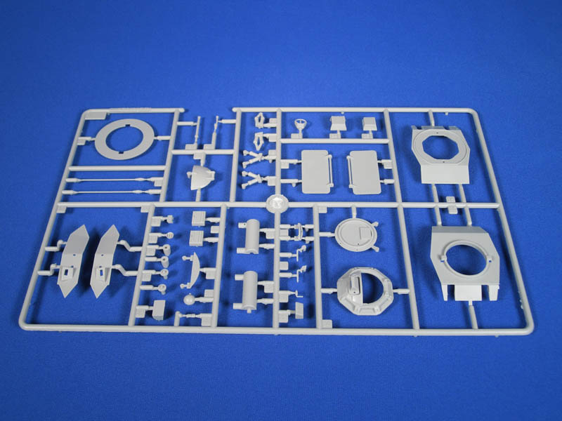
THE TURRET
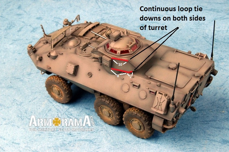
The Cadillac-Gage One Meter Turret held the firepower of the Grizzly. The turret in the kit can be built to permit the guns to elevate and depress, with the choice of having both the hatch and the sight cover open or closed. A great feature is the inclusion of the vision blocks as separate clear parts. This will allow the modeller to achieve the clear deep green colour before attaching them to the turret.Besides the obvious lack of instructions for the assembly of the turret there are issues that may or may not be apparent to the modeller as the build progresses. As much as every kit should be judged on its own merits the ability to compare parts with other kits that are accurate is critical in providing a modeller with tools to make an informed decision. As a result I compared the shape, angles, and overall dimensions of the kit turret parts with the Azimut M113A3 TLAV turret. Some modellers have already described the assembled Trumpeter turret as looking as though it is backwards. Well, it a sense that is correct. The angles of the kit turret when compared to the Azimut turret do not line up. But, when the kit turret is turned 180 degrees around the angles are near perfect matches to the Azimut turret. How Trumpeter got this totally wrong and created the turret angles backwards I do not understand with the ability to use CAD drawings and comparisons to a variety of reference sources. This turret problem is very disappointing and pretty much a deal breaker for this kit. The biggest question now is can this be fixed. I think it can be fixed but it will take major plastic surgery. The front and rear angles on both parts H28 and H35 will have to be carefully cut off and reattached on opposite ends. The turret side pieces, H10 and H11, will have to have the grenade mounts removed and the resulting holes and the grenade box holes will have to be filled in. This solution will have to take lots of planning and test fitting and no doubt the use of putty to blend in the parts. If Trumpeter staff is reading this review they need to fix this issue above all other issues in the kit immediately. On a positive note part H34, the turret top, appears to be correct in dimensions when compared to the Azimut turret. The machine guns dont look as they should be. Both the .50 Cal HMG and the C6 GPMG have a fluted muzzle flash suppressor and look toy-like. This is not accurate for the guns fitted to the Grizzly turret. The barrels also appear thick and oversized. They would best be replaced to make them accurate and visually appealing.The grenade dischargers on either side of the turret look overall nicely produced. The caps are a bit stiff looking compared to the real deal but should be able to be made to look correct. The mounts however should not be solid as displayed on the parts. This will take more work to rectify as they will have to be removed and scratch-built open mounting frames created. If you take this route you may as well add the electrical wiring on the back side of the bracket as well. The grenade boxes are correct, but should stand off from the turret a bit and sit on brackets.The top of the turret, part H34, is very nicely molded. The only issue I can see is a missing electrical connection to the right of the sight. This is where the electrical cord for the spotlight attaches. Bolt and bracket detail is included for the vision blocks but in reality these should extend just slightly on to both sides of the vision blocks. The gunners hatch has a few issues. Number one, there is no interior detail and this is not accurate. The complete locking mechanisms will have to be scratch-built to pose the hatch open. Number two; there should not be an external handle on the outside of the hatch. Just sand it off. Number three; the actual hatch is not completely rounded on the outside. There should be a distinct flat rectangular portion on the middle portion of the outside of the hatch. This is for the internal locking mechanism. The spotlight is pretty basic and needs an electrical connection added to the backside. The vertical strip on the spotlight guard, part H23, should be a tad thinner. On the rear of the upper turret, part H28, there should be a few details for the bracket for mounting a machine gun tripod. There should also be a small half circle lifting eye on the back of the turret. Both of these features are nonexistent in the kit. They will have to be scratch built with the use of some good references. On both sides of the turret, parts H10 and H11, there should be lengths of continuous tie downs on both the top and bottom edges of the turret. See the Trumpeter photo of the completed kit for the placement and number of the tie downs. The turret sight is basic and lacks the small double wiper system that should be visible if the sight cover is open. So, in the end we have a turret with what appears to have good dimensions but the lack of details and a major inaccuracy take away from its looks.
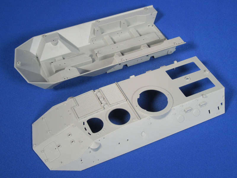
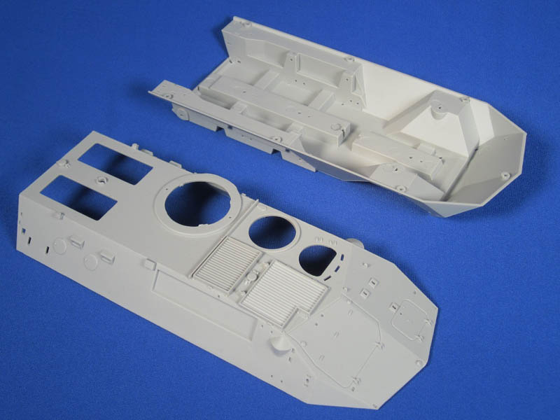
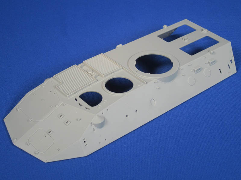
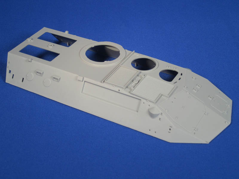
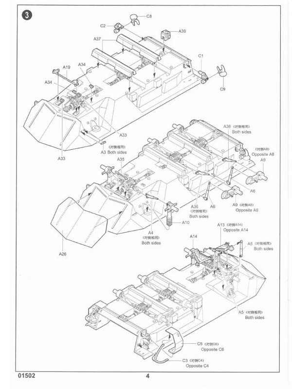
THE HULL
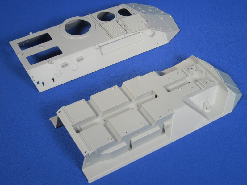
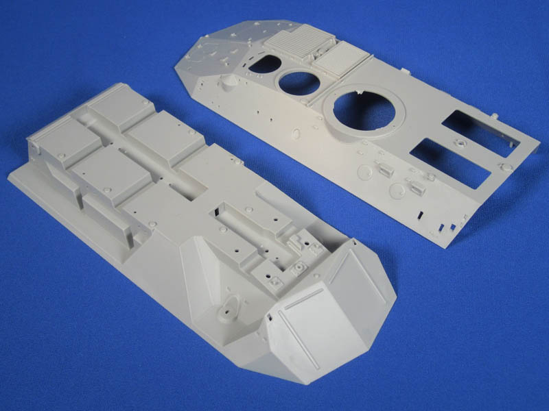
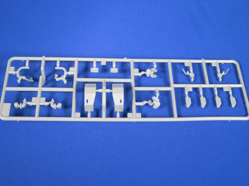
I wanted to start fresh with the hull but I knew immediately the first time I looked at the Trumpeter build images that there were detail and accuracy issues. Some of these issues are barely noticeable, some of them are easy fixes, and some will require more than a bit of sanding and trimming. To begin the actual hull dimensions seem to be pretty much correct in 1/35 compared to the real vehicle. This is encouraging. The hull components are not molded as nicely as the turret parts. There is some flash and injector pins marks are more easily visible. The upper and lower hulls are provided ready to assemble. There is no cleanup required and the two parts fit nicely together. The instructions show parts added to the lower hull and the upper hull and then the two are mated together. With small parts this may not be a desirable way to assemble the kit so modellers may want to assemble the basic hull first and then add the details. There are pros and cons to this approach and as you will see with the corrections needed it might be better to deal with the fixes and then attached the parts together. Looking at the hull front there are two holes indicated in the instructions on the front lower hull that need to be filled in. This is 100% correct. These are locating holes for small towing eyes. They are only present on the late version AVGPs where the trim vanes have been removed. This is another indication that we will likely see a late version Grizzly. The trim vane looks accurate and included in the kit is the attachment for the air-driven piston to move the trim vane up and down. The front upper hull has molded-closed hatches for the winch cover (the winch was not fitted on the Cougar or Grizzly, only the Husky) and both engine hatches. There is a visible issue with the engine air intake grills. There is a raised lip around the edges of both sets of grills. This should not be visible and should be shaved or sanded down. The placement of the two grills is also not correct. Both grills should be inset a bit further from the right upper edge of the hull. The kit has the forward grill almost flush with the hull edge, and the rear grill inset only a little. This will require cutting, sanding, and some rebuilding. Both open and folded wire cutters are provided for the driver. This is a nice option to include in order to give your Grizzly a different look. The headlight, blackout markers, and mirror mount assemblies are included but basic. The mirrors are incorrectly shaped and should be curved on both ends and not squared off. The mirror mounts are not correct and over simplified as are the two small blackout markers. The drivers hatch area includes some details that could use some refinement. The three periscopes should in fact have a separate cover over each of them and not one molded solid. The hatch is acceptable and can be positioned opened or closed but needs a bit more detailing with locking mechanisms. The kit provides the option for the drivers windscreen. This is also a nice inclusion and it actually looks fairly accurate. It consists of the frame, three clear pieces for the glass, and a wiper blade. The main parts that are missing are a small electrical motor that should be on the opposite side of the where the wiper blade attaches, a carrying handle that attaches over the wiper blade on the top of the frame, and a pivoting lock on the lower left mount of the frame. If you are going to add the windscreen make sure you mount the drivers hatch open, and there should also be a small electrical cable that runs from the windscreen to an electrical connection to the left of the left periscope. Moving to the commanders hatch it perplexed me why Trumpeter provided all other crew hatches open and yet this hatch is molded closed. It will take some significant surgery to open this hatch. The vision block and hatch lock are nicely molded. The kit should have included three additional hatch locks for the two upper rear hatches and the drivers hatch but they are absent. Behind the commanders hatch there is a small oblong hatch molded on the upper hull. This is for the crew heater intake and exhaust. Trumpeter placed the part 180 degrees backwards. The large part of the oval should face towards the hull rear when closed. Moving to the right side of the hull the exhaust port is molded solid and will need to be hollowed out. The two side vision blocks in my opinion are correctly sized and placed. They should have small weld beads around the outer edges that touch the hull. The accuracy issue here and echoed on the other side of the hull is that the two circular rifle ports are not correctly placed. They should be raised slightly and moved right slightly closer to the vision blocks. There should also be two small blocks welded on the hull for each rifle port. When the rifle port is closed one of the blocks should be positioned at the 9 oclock position resting against the rifle port. The second block should be positioned at the 7 oclock position about 2 mm from the rifle port. These blocks act as stops for when the rifle ports are rotated on the inside from the closed to open positions. The small raised pin on the kit rifle ports should be at the 6 oclock position and not at the 9 oclock position as displayed in the kit. If you want to correct the position of the rifle ports you are probably better to sand them off and make new ones and place them in the correct position. The antenna mounts that are provided are adequate. The antennas included are too short and should be about 93 mm long. On the top of the rear hull are two hatches, the cover for the exhaust fan, and the fuel cap cover. Once again the hatches are provided separate and could be modified to be attached open with a bit of cutting and re-gluing. Missing from the upper rear hull area are all of the pioneer tool brackets that should be between the turret and the hatches, and the hatch locking mechanisms. This is where two more of the commanders hatch locks would have been perfect. With all that missing detail it amazed me that the small molded on fuel filler cap cover includes very nice details with the hinges and the locking tab. Moving to the hull rear the taillights are unfortunately molded as one piece and this creates a complete lack of definition with the actual lights. These parts should be replaced with some tubing and a separate taillight if possible. Both rear doors are included so that they can be attached. This is great if someone wants to scratch-build an interior. The main issue with the doors is that they should sit flush with the rear hull when closed but they sit noticeably raised. This again will require plastic surgery. It is encouraging that the door handles and door hold open locks are included. Also included is a door lock that is only fitted on late version Grizzlies, parts H20 and H29. Dont fit these parts for an early or mid version Grizzly. Unlike the hull rifle ports Trumpeter actually got the rear door vision blocks and rifle ports correct. They are positioned correctly and the bolt detail is where it should be. To finish up with the left rear door do not mount the shovel, part B6. The Grizzly did not mount the shovel here as it was mounted on the upper rear hull in front of the hatches. Each marine drive unit consists of six parts including the propeller, the two rudders, the marine drive unit, and the guards. Overall these parts are pretty good. There is a lot of flash on the guards in my review sample and one of the parts is molded bent. On the inside of each large guard, parts C5 and C6, there are large sink marks that will need filling. On the bottom surface where the pin marks are there should be a hole that aligns with the small plug on the bottom of part C1 and C2. These holes were for accessing the drain for the marine drive fluids. Take your time with the assembly of these parts as they overlap and alignment is critical. The jerry cans on both sides of the rear hull are very rudimentary and a step back with current day molding. They are a two piece jerry can with the racks and straps molded on. This creates awkward seams on the handles and caps. They appear to be modern style water cans and should in fact be fuel cans. The position of the jerry can racks on the hull sides is too low. The bottom of the jerry can rack should be level with the bottom of the angled portion of the antenna mount. In the kit they sit considerably lower. They can be raised but the very big locating holes will need to be filled. Looking at the vision blocks and the rifle ports on the left side of the hull additional issues are located. Not only do the rifle ports have the same issues as identified on the right side, the problem is amplified by the fact that the actual vision blocks are improperly positioned on the hull. Both vision blocks need to move to the left about 2mm so the right edge of the right vision block is in line with the left edge of the upper left hatch bumper
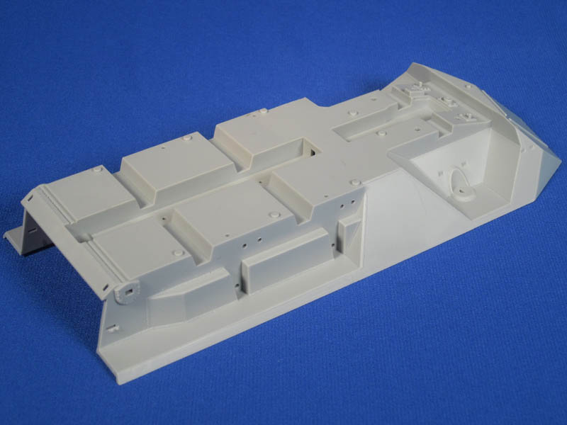
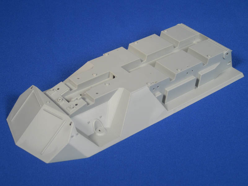
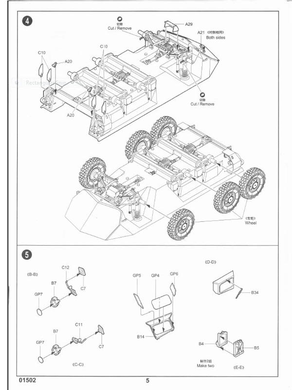
clear as mud? The tie downs on the entire hull are molded as solid blocks. This is not uncommon on many plastic models and can be replaced if you desire. The good thing is that they are in the right locations for a start point. Unlike the Cougar AVGP the Grizzly AVGP does not have tie downs running down the lower edge of the upper hull so you wont see them on the Grizzly kit. On the mid portion of the left side of the hull the instructions indicate to mount parts H3, H24, and H25. These are communications components that were only mounted on the late version Grizzly. This is another indication that a late version Grizzly kit is inevitable. You will have to fill the large locator hole for part H13 and the smaller holes for part H25. The handholds and signal lights are a nice inclusion for the hull. There are also two small photo etched parts included for the signal light guards. These are in fact the early version Grizzly style. The mid version had angled guards added on the front portion. You can still use the kit parts as the modification occurred over time. As a positive there are some nice subtle weld marks molded on for the front wheel strut housings and around the turret ring. An issue identified with the Trumpeter Cougar AVGP hull and carried over to the Grizzly kit is the spacing of the lower hull sponsons for the right and left third wheels. The left side is correct, however, the right side needs to be extended about 2 mm. This is difficult to explain in words so images are the best way to show the correction needed. I will direct you to this link to the Modern Canadian Vehicles forum to show the error.
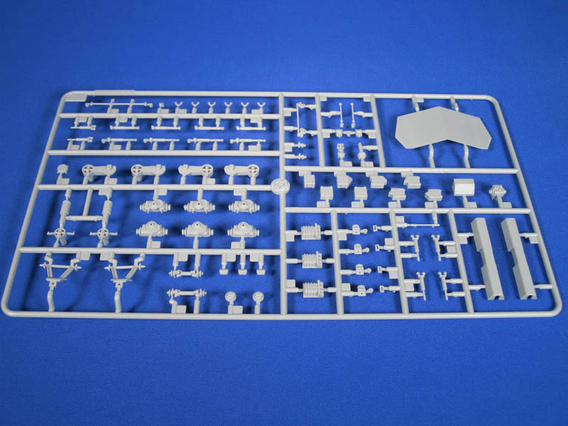
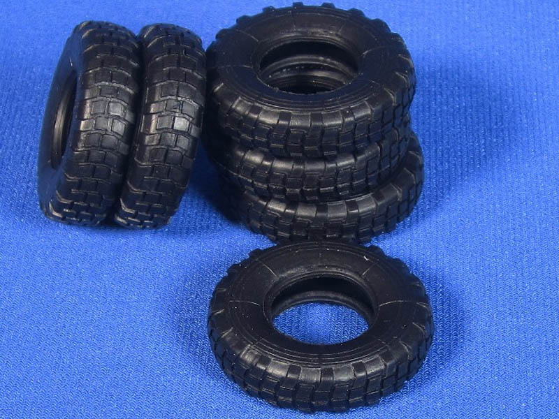
Sponson error correctionLooking at the suspension we can start with the tires. The tires are molded in black vinyl. They are the correct style for the early and mid version Grizzly. Be mindful of the instructions as they indicate fitting the tires to the wheels with the tread in the wrong direction on one side. The tires are directional and the chevron pattern should be angled downwards to the front of the vehicle. There are always exceptions and sometimes tires were fitted in the opposite direction due to availability of left and right tires. The tires are void of any raised lettering. This of course is not accurate and there are several aftermarket resin tire sets if you want to replace the tires. Moving back along the hull parts A26, A38, and A39 are the brake and vent line covers for the rear four wheels. The parts are shaped correctly but should be open on the bottom and rear facing sides. If you do open up the guards thin out the plastic as these should simply be thin metal covers. While the parts can be tweaked they should actually be replaced by other later version parts. Parts A27, A28, A40, and A41 are included but not used in the instructions. They include an additional angled portions on the bottom that was added during the lifespan of the Grizzly to aid in reducing the brake lines getting ripped off while travelling cross country. If you are wanting be build a mid version Grizzly then use parts, A27 (left mid), A28, (right mid), A40 (right rear), and A41 (left rear) in lieu of the original parts. Once again you will have to open up the bottoms and rear sides of the guards. Looking at suspension components it is always a trade-off of accuracy, the ability to assemble components, and accepting what is actually visible or not visible on a completed model. Without a doubt there is some simplification of the suspension components but they are not overly visible. On the ends of each front suspension A frame that should be conical-shaped guards. These are included in the kit as narrow arrow like shapes. The front steering components are not designed to allow the front wheels to be turned but this can be modified with some key cutting and moving of parts. On the front suspension there are parts A5 x 4 included. These parts when fitted are the dual shock modification that was done on all AVGPs in the late 1980s and correct for all versions of the Grizzly but not an early version prior to about 1988/1989. The steering stops that limit the amount of turn of the wheels are missing on the kit hull. This is an easy fix and can be added to the hull bottom in front of where the turnbuckles to parts A19 and A21 attach together. On the back of the hull bottom the instructions indicate to attach parts A20 x 2. These should be towing points but appear sized down and should be larger like parts B20 used on the front and rear hull. Some nice fine weld detail is included in the wheel wells and it appears all the drain plug locations on the bottom hull are correct.
CONCLUSION
It is encouraging in these times that model producers are creating models that have up until now only existed in resin or conversion form. That is terrific but what continues to amaze me is that some simple research still evades one of the biggest model producers as the kits are in the developmental stage. This leads to major inaccuracies when the kits go out to the hard-earned-dollar spending public. This kit alleges to use modern slide molding technology and it is fantastic to see well detailed parts that are nearly void of injection pin marks and need little cleanup. But that detail is greatly overshadowed by a very large list of inaccuracies. Beyond the accuracy issues the kit has tons of potential for further detailing but will require significant corrections and modifications to make it look like an accurate Grizzly AVGP. While it is very satisfying to have plastic AVGPs finally available it is disappointing that the kit is so flawed from the parts, to the paint guide, to the instructions, and even to the version the kit it is advertised to be. Would this have occurred if this kit was of a German WWII AFV? I applaud Trumpeter for creating the AVGP series in plastic but I hope any other AVGPs produced by Trumpeter are corrected before they hit the shelf. They owe it to themselves and to modellers. For those wanting to build an accurate Grizzly AVGP I cannot recommend this kit.


Comments