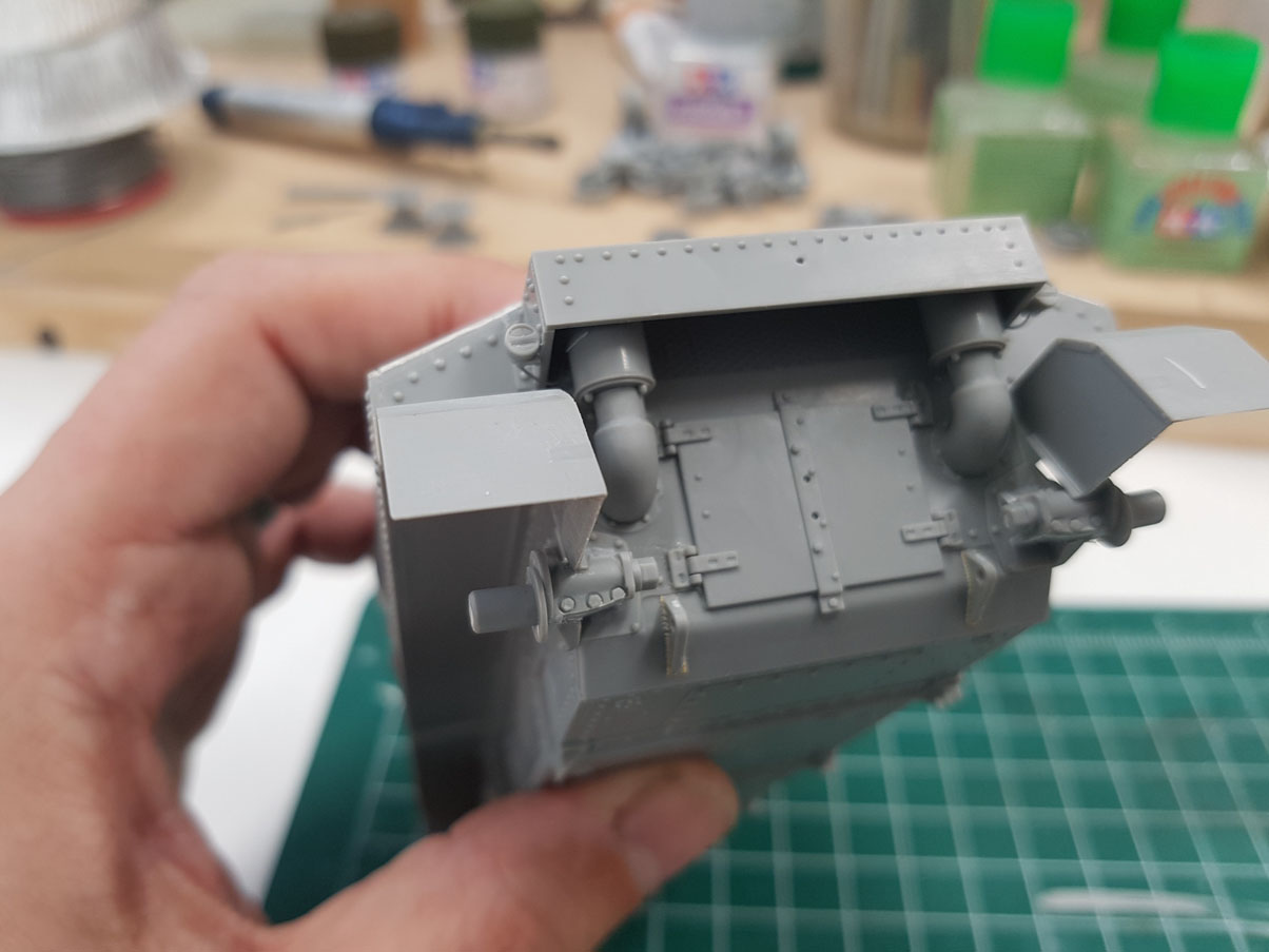
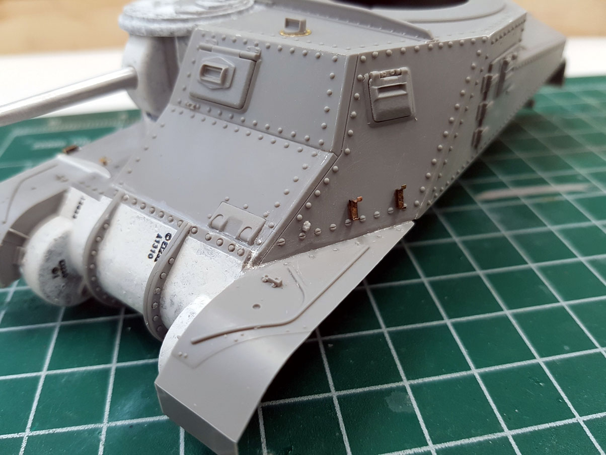
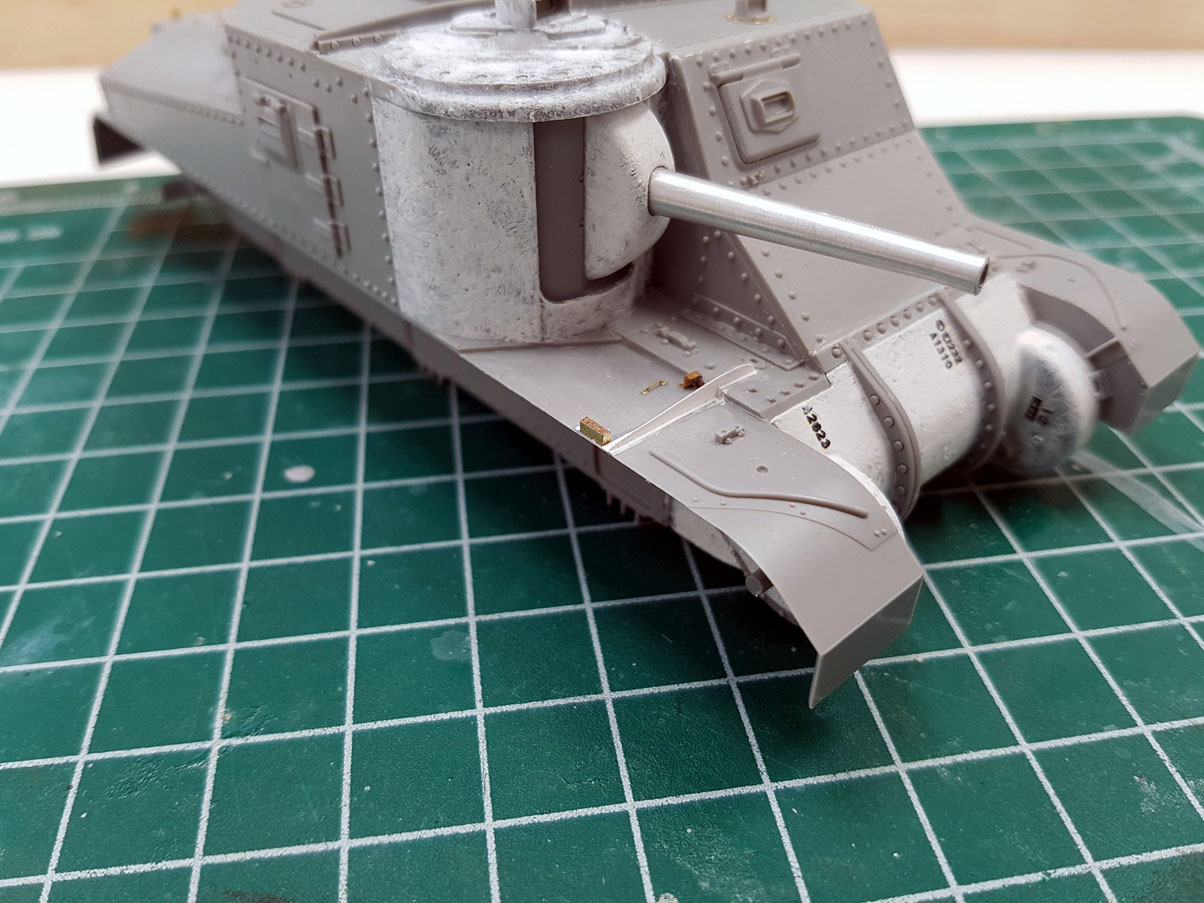
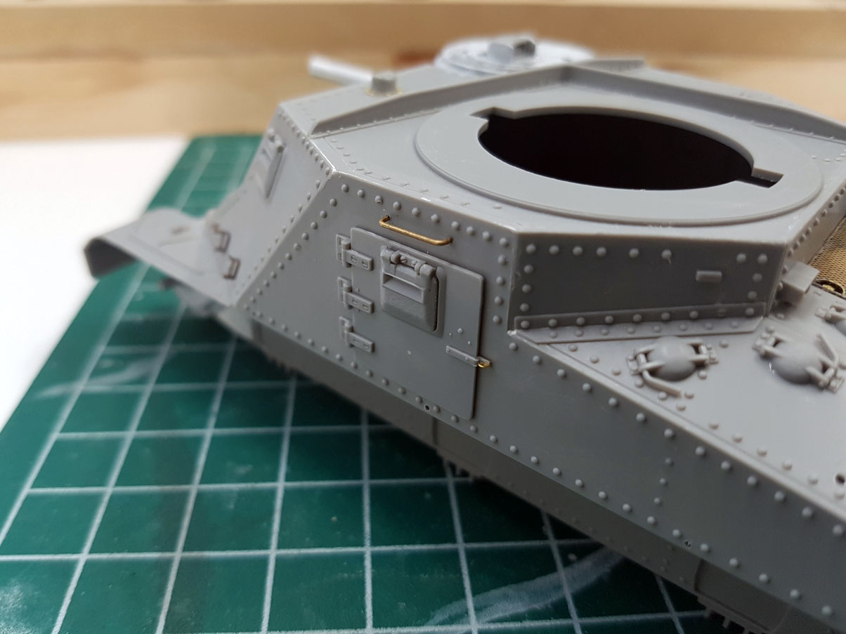
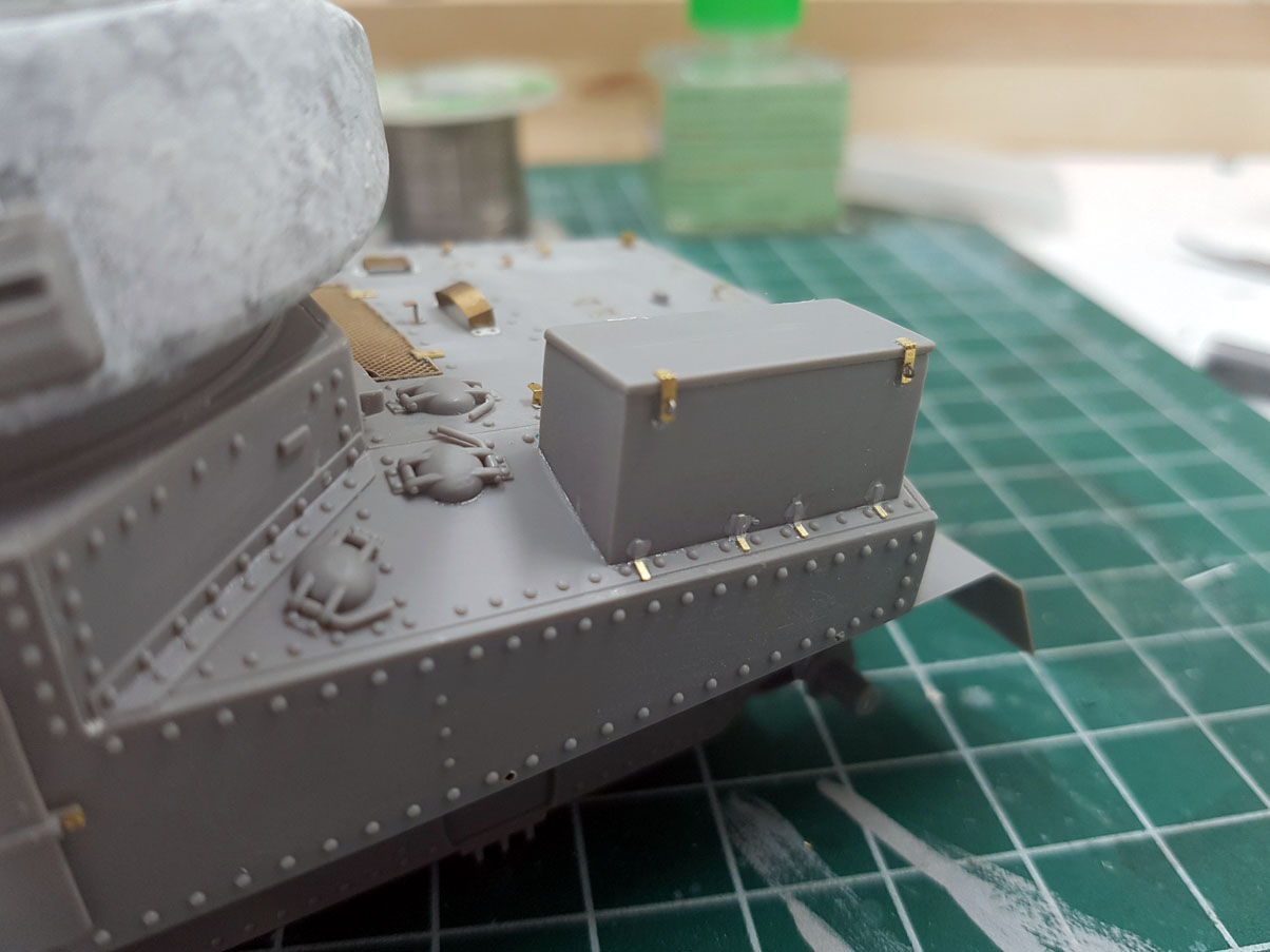
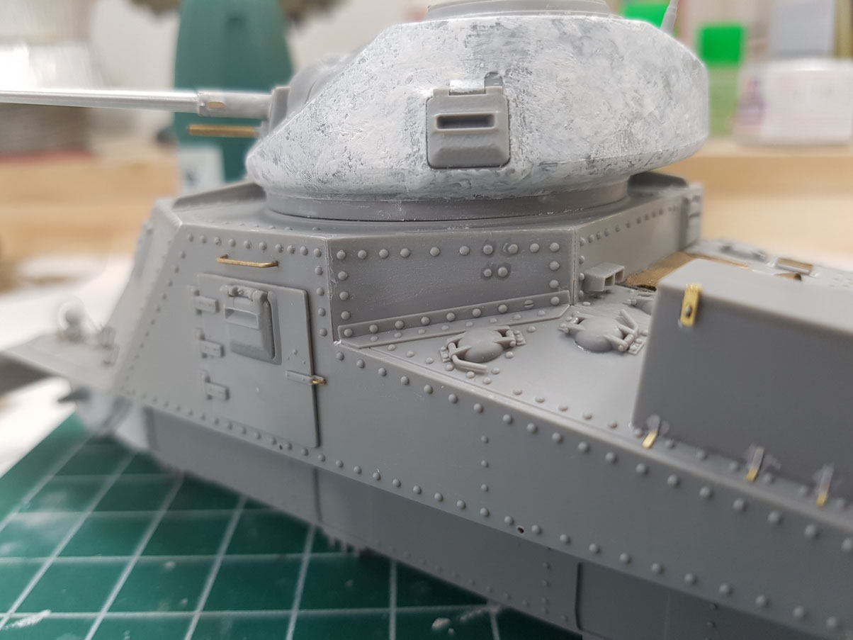
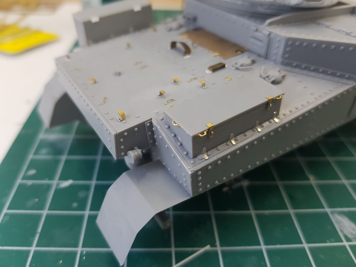
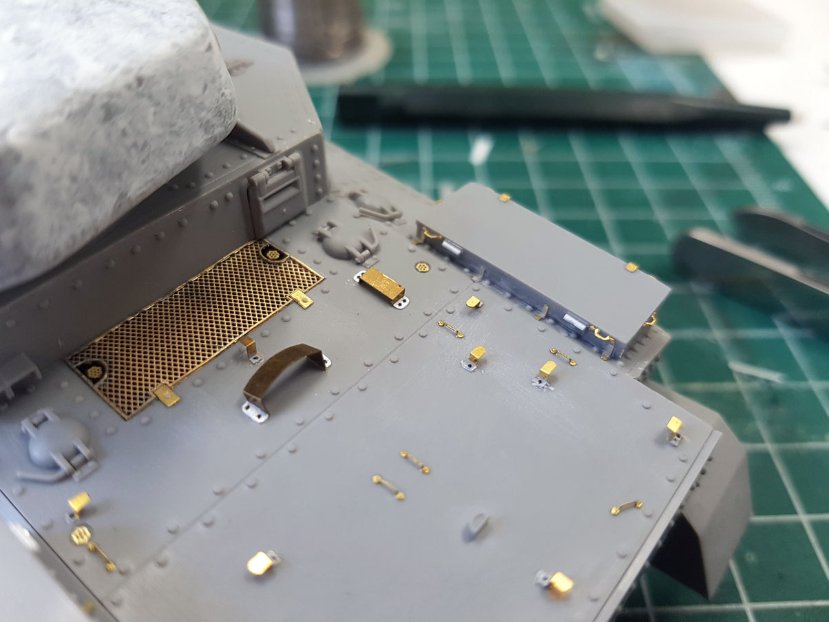
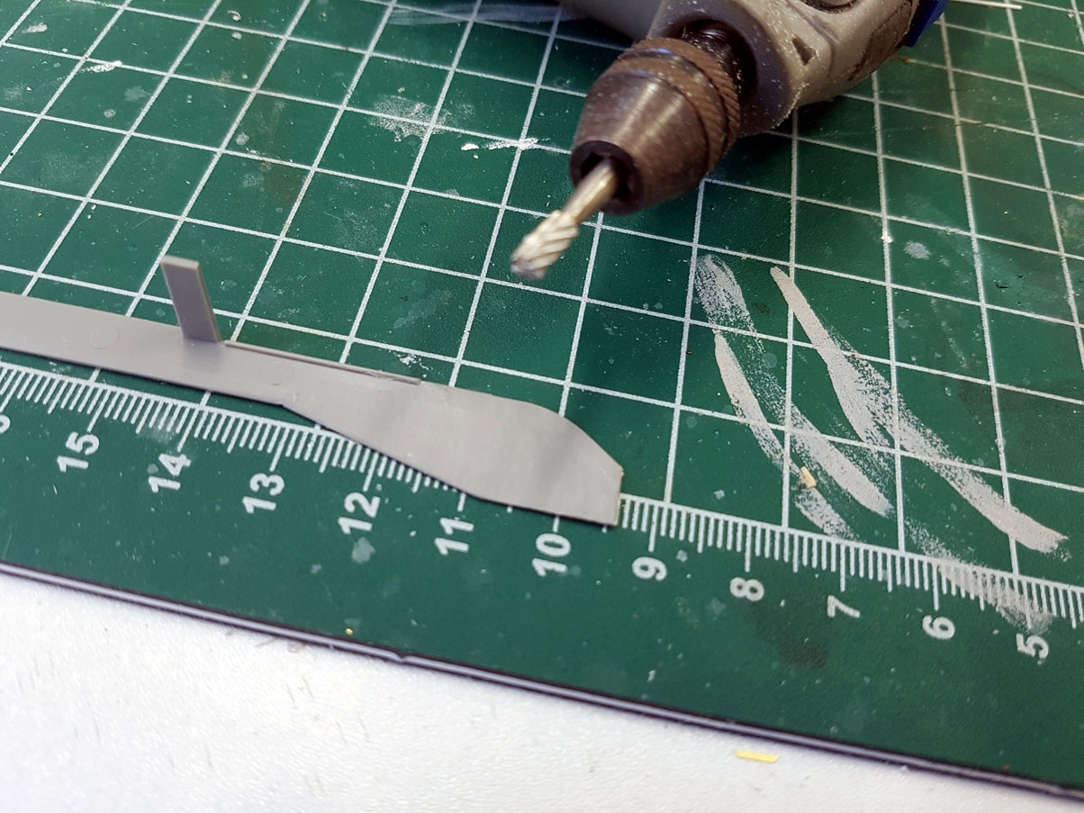
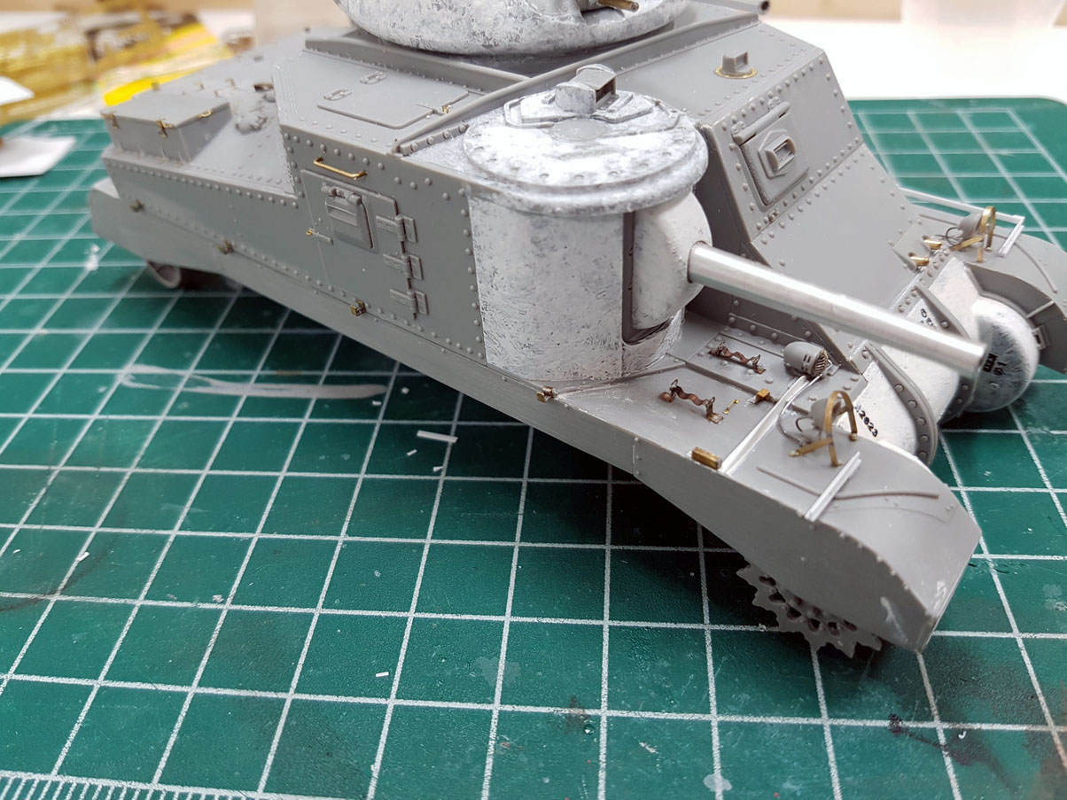
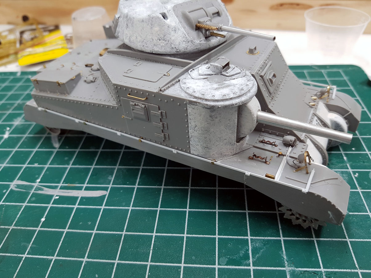
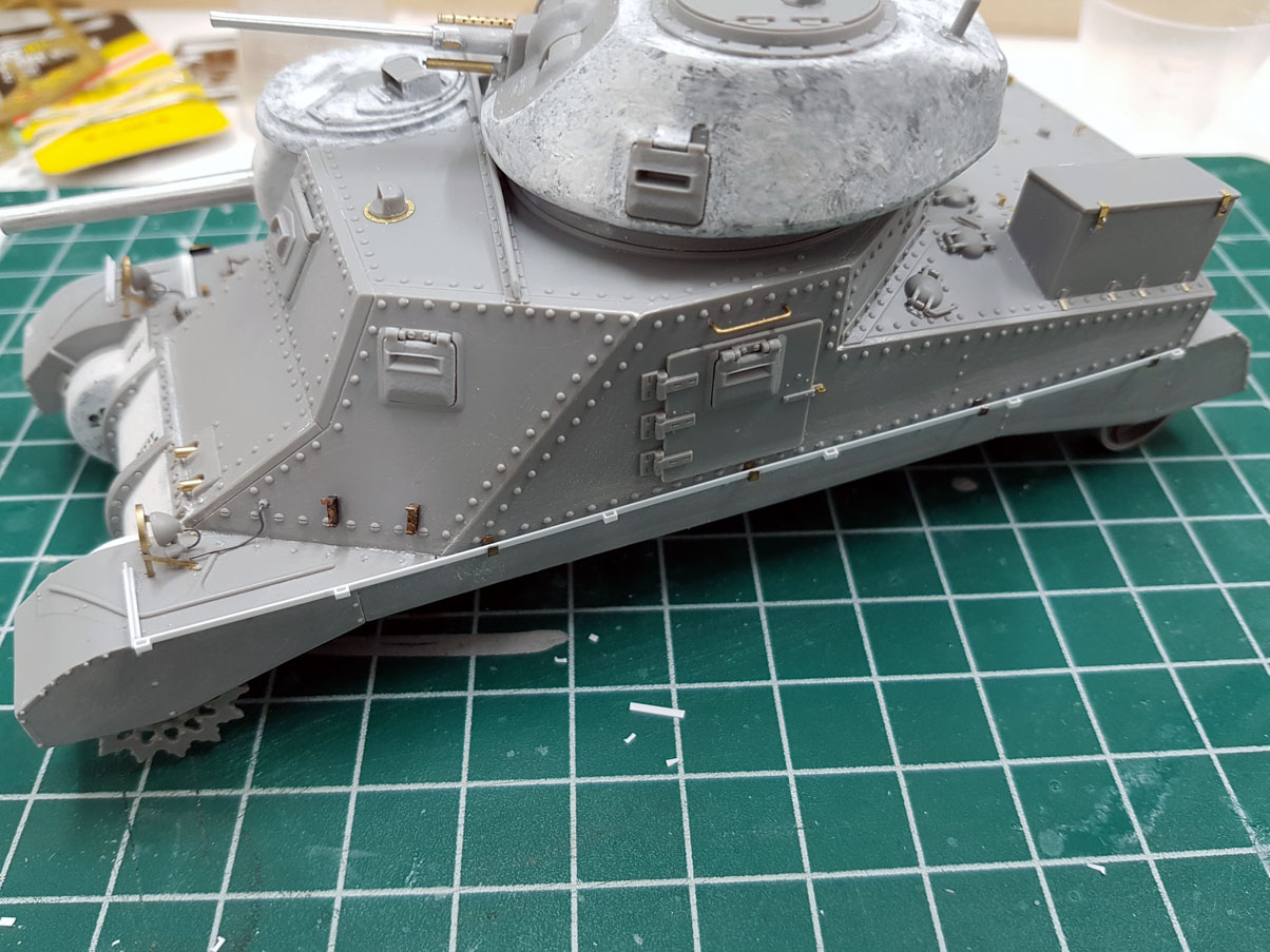
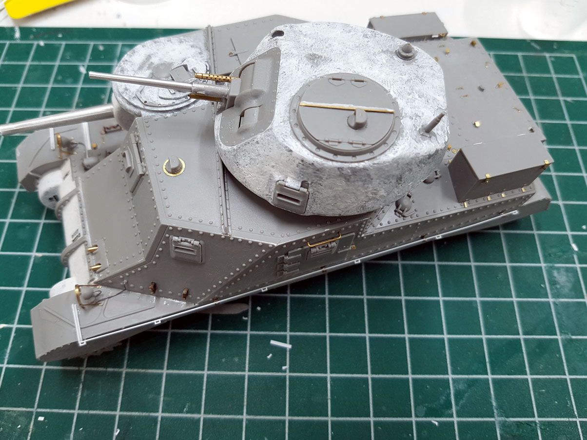
Armor/AFV: Allied - WWII
Armor and ground forces of the Allied forces during World War II.
Hosted by Darren Baker
Takom M3 Grant
JSSVIII
Visit this Community
Massachusetts, United States
Joined: March 28, 2007
KitMaker: 1,169 posts
Armorama: 1,067 posts
Posted: Thursday, October 12, 2017 - 04:24 AM UTC

Quoted Text


Quoted Text

Fitment, is, to say the least, a real challenge. I ended up removing the locating tabs and increasing the angle of the chamfer so the edges actually touch where they are meant to. Even so, I still had to use a fair amount of putty to full annoying gaps...


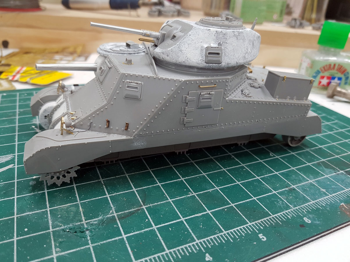
I've seen this comment about this kit in several places now. Apparently, a couple of guys have had better luck fitting the superstructure parts together by starting to match things to the top plate rather than working up from the lower hull.

I haven't tried it yet, but I have seen this as a suggestion to fit things better.

Just a thought for those who haven't built it yet.

Paul


Thanks for mentioning that Paul, seems like an interesting solution, now I'll have a couple of options to try when I get mine.
Bravo1102
Visit this Community
New Jersey, United States
Joined: December 08, 2003
KitMaker: 2,864 posts
Armorama: 2,497 posts
Posted: Thursday, October 12, 2017 - 11:35 AM UTC

Quoted Text


Quoted Text

From photos with all the storage and most taken from the front the different rear deck and exhausts are nearly impossible to discern. And unlike a M4, versus M4A2, M4A3 the angles on the rear are identical . . .


The diesel-engined rears are different angles. The diesel tanks have long, sloped rear plates while the Wright-engined tanks have short, vertical rears and the M3A4s have full-width, sloped plates with two exhaust pipes. This is apparent in any side view taken from slightly forward of center to the back. Also, nearly any welded hull tank is a diesel M3A3 as there were only 12 gas-engined tanks with welded hulls built. (Versus 322 M3A3s.)

KL


The rear is either not visible or obscured with storage. The difference (and I know about the rear slope, I built a kit of one) is essentially invisible in nearly all pictures. There are more hints on the rest of tank to tell an M4 from M4A2 and M4A3 than on a Grant. There is nothing but the rear and the engine deck.

I'll not be getting the Takom kit yet as I found an Airfix 1/32 One. The hull on that is broken down similarly but Airfix has tabs that root the front hull to the suspension to provide a firm base to assemble the rest of the hull. The Takom superstructure part break down also reminds me of the Academy and that kit fought me every step of the way.

Almost makes you yearn for the slide molded one piece superstructure of the Tamiya or Monogram kits. Almost.
gastec
Visit this Community
Auckland, New Zealand
Joined: February 03, 2014
KitMaker: 1,042 posts
Armorama: 871 posts
Posted: Thursday, October 12, 2017 - 12:43 PM UTC
Fair bit of progress over the last couple of days and will upload some images over the weekend.

In the meantime, anyone know what these brackets are for?


Gary
GazzaS
#424
Visit this Community
Queensland, Australia
Joined: April 23, 2015
KitMaker: 4,648 posts
Armorama: 2,248 posts
Posted: Thursday, October 12, 2017 - 01:20 PM UTC
On this plans from The Blueprints, it looks like pioneer tool brackets:


ericadeane
Visit this Community
Michigan, United States
Joined: October 28, 2002
KitMaker: 4,021 posts
Armorama: 3,947 posts
Posted: Thursday, October 12, 2017 - 03:16 PM UTC
Those brackets are one of two stowage mounts for the .30cal MG tripods. There are similar brackets on the angled plate above the left sponson too
KurtLaughlin
Visit this Community
Pennsylvania, United States
Joined: January 18, 2003
KitMaker: 2,402 posts
Armorama: 2,377 posts
Posted: Thursday, October 12, 2017 - 03:27 PM UTC

Quoted Text

Fair bit of progress over the last couple of days and will upload some images over the weekend.

In the meantime, anyone know what these brackets are for?


Gary


Cal. .30 tripod.

KL
gastec
Visit this Community
Auckland, New Zealand
Joined: February 03, 2014
KitMaker: 1,042 posts
Armorama: 871 posts
Posted: Friday, October 13, 2017 - 04:40 AM UTC
Thank you gentlemen


Kit PE isn't up to the standards of the likes of Voyager - especially the mesh which is, iMHO, awful...


Looks even worse in the flesh.

So, I cut out the mesh, leaving the frame, and soldered so other mesh from the spares box...


Much better methinks...


Tool brackets are from spares box or made from scrap PE....


Rear lights get some wiring - yet to add handle for doors...


.30 cal tripod brackets are remade from spare PE parts....


Tool brackets on fender along with RB Models 75mm M2 L/31 barrel....


Big improvement on the kit offering. I'm also wondering if Takom got the 37mm barrel wrong as there seems to be rather a larger step down in diameter from the large tube section? Doesn't seem to be that noticeable on the real thing. The RB offering also differs...


.30 cal co-ax is dry fitted at this stage...


Grab hadles are made from brass wire with PE padlock clasps replacing moulded on ones...


Still a long way to go, but progressing well I think...


Gary
JSSVIII
Visit this Community
Massachusetts, United States
Joined: March 28, 2007
KitMaker: 1,169 posts
Armorama: 1,067 posts
Posted: Friday, October 13, 2017 - 05:00 AM UTC
Very nice progress Gary, Very nice!
d6mst0
#453
Visit this Community
Texas, United States
Joined: August 28, 2016
KitMaker: 1,925 posts
Armorama: 601 posts
Posted: Friday, October 13, 2017 - 06:51 AM UTC
I would say things are progressing very well. Very nice PE work. Looks like I will my work cut out for me when I start this kit, but not anytime soon. I have to many other kits in the Q...
gastec
Visit this Community
Auckland, New Zealand
Joined: February 03, 2014
KitMaker: 1,042 posts
Armorama: 871 posts
Posted: Friday, October 13, 2017 - 09:14 AM UTC
Thanks guys.

Scratchbuilt tripod brackets....


The light guards are okay but lack proper detail. Real ones are 3 piece - main hoop and 2 legs. Takom supply the PE so it looks like a single piece. So off with the 'old' legs and on with some new....


Lights etc are added along with wiring...


Decided to depict both .30cal hull MGs in the end...


Gary

27-1025
Visit this Community
North Carolina, United States
Joined: September 16, 2004
KitMaker: 1,281 posts
Armorama: 1,222 posts
Posted: Friday, October 13, 2017 - 11:28 AM UTC
Inspiring stuff, especially with the additional PE and casting marks. Great tutorial on how to build this kit. Look forward to seeing it under paint.
Bravo1102
Visit this Community
New Jersey, United States
Joined: December 08, 2003
KitMaker: 2,864 posts
Armorama: 2,497 posts
Posted: Friday, October 13, 2017 - 12:47 PM UTC
Really a great walk through on this kit. Really shows a lot of attention to the details. Dunno, it doesn't seem the big step up from Academy's offering that I was hoping for.

Many operational pictures show that if the counterweight under the 37mm is fitted the one on the 75mm will also be in place? I'm not conversant enough with the production updates and retrofitting to say if one didn't precede the other or they both arrived at once.
ReluctantRenegade
Visit this Community
Wien, Austria
Joined: March 09, 2016
KitMaker: 2,408 posts
Armorama: 2,300 posts
Posted: Friday, October 13, 2017 - 01:28 PM UTC

Quoted Text

Dunno, it doesn't seem the big step up from Academy's offering that I was hoping.


My thoughts exactly. I was hoping for a somewhat more trouble free fit. I wanted this kit badly but I think I'll pass, at least for now...Thanks for the detailed insight Gary, excellent work indeed!
gastec
Visit this Community
Auckland, New Zealand
Joined: February 03, 2014
KitMaker: 1,042 posts
Armorama: 871 posts
Posted: Friday, October 13, 2017 - 02:24 PM UTC

Quoted Text


Many operational pictures show that if the counterweight under the 37mm is fitted the one on the 75mm will also be in place? I'm not conversant enough with the production updates and retrofitting to say if one didn't precede the other or they both arrived at once.


Interesting point. Had a quick look at some google images which seems to support this theory. Anyone have some definative answers otherwise I may look at removing the weight under the 37mm barrel?

Gary
KurtLaughlin
Visit this Community
Pennsylvania, United States
Joined: January 18, 2003
KitMaker: 2,402 posts
Armorama: 2,377 posts
Posted: Friday, October 13, 2017 - 08:36 PM UTC

Quoted Text


Quoted Text


Many operational pictures show that if the counterweight under the 37mm is fitted the one on the 75mm will also be in place? I'm not conversant enough with the production updates and retrofitting to say if one didn't precede the other or they both arrived at once.


Interesting point. Had a quick look at some google images which seems to support this theory. Anyone have some definative answers otherwise I may look at removing the weight under the 37mm barrel?

Gary


Both are artifacts of the stabilization system. As a rule, but not exclusively, a tank with an M3 or counterweighted M2 gun in the M1 mount will also have a counterweight on the M24 mount. It's odd that the M24 would be out of balance because I don't think there were any designs for a longer 37mm gun.

There was a standard counterweight (B197508) but it appears that regular plumbing pipe and fixtures were just as common.

KL
rfbaer
Visit this Community
Texas, United States
Joined: June 12, 2007
KitMaker: 1,866 posts
Armorama: 1,696 posts
Posted: Friday, October 13, 2017 - 10:12 PM UTC
Superb detail work, as usual. Thumbs up!
gastec
Visit this Community
Auckland, New Zealand
Joined: February 03, 2014
KitMaker: 1,042 posts
Armorama: 871 posts
Posted: Saturday, October 14, 2017 - 02:14 AM UTC
Thanks Kurt. I'll leave the counterweight where it is since I went to the effort to scratch build it. Plus it adds some visual interest.

Gary
gastec
Visit this Community
Auckland, New Zealand
Joined: February 03, 2014
KitMaker: 1,042 posts
Armorama: 871 posts
Posted: Saturday, October 14, 2017 - 05:39 AM UTC
Cheers Russel.

Second headlight assembly. Jig supplied by Takom is very useful....


All in place along with wiring...


I'll add the lenses after painting to save having to mask them.

Stowage box detail is improved by adding PE clasps and some better defined hinges...


Small L shaped mouting brackets are provided by Takom on the PE fret.


I also just picked this up - can't believe I didn't notice it earlier - but there is a mounting tab on the rear plate where the antenna mount goes which is only applicable to the Lee. Takom make not mention about this in the instructions. You can see it in the above image. Pretty obvious when you notice it!!!

So off came the tab and I added some more rivets after looking at a couple of walkaround images of the real thing...


Gary
gastec
Visit this Community
Auckland, New Zealand
Joined: February 03, 2014
KitMaker: 1,042 posts
Armorama: 871 posts
Posted: Saturday, October 14, 2017 - 12:51 PM UTC
The other stowage box is a little more involved due to it having 6 tie tie down loops on the lid. Otherwise process is the same as oher bin...


Side shields next. With the drive sprocket and idler wheel slotted onto their respective axle, the shields can be fitted into place. However, I did find that the front end wouldn't fit correctly and I needed to thin down the section level with the sprocket. Once I did this, the shiled fitted fine, needing minimal filler along the joints...


I found that some of the fastener head detail became 'compromised' while sanding the filler, so I opted to remove all the moulded on ones (they were very small anyway) and replace them with slightly larger ones which will show up better once covered with paint. I also had a slight accident with the cement and damaged the suface, hence the white filler marks where I sanded things smooth again.

Second side WIP...


Gary
Bravo1102
Visit this Community
New Jersey, United States
Joined: December 08, 2003
KitMaker: 2,864 posts
Armorama: 2,497 posts
Posted: Saturday, October 14, 2017 - 01:51 PM UTC

Quoted Text


It's odd that the M24 would be out of balance because I don't think there were any designs for a longer 37mm gun.

There was a standard counterweight (B197508) but it appears that regular plumbing pipe and fixtures were just as common.

KL


Physics. Imagine the gun mount rotating end over end. The length of the gun tube is unbalanced with the width of the gun breech. So the length needs to be widened to accommodate. Adding a tube under the main gun barrel does this.

Things my Master Gunner taught me.
KurtLaughlin
Visit this Community
Pennsylvania, United States
Joined: January 18, 2003
KitMaker: 2,402 posts
Armorama: 2,377 posts
Posted: Saturday, October 14, 2017 - 06:31 PM UTC

Quoted Text


Quoted Text


It's odd that the M24 would be out of balance because I don't think there were any designs for a longer 37mm gun.

There was a standard counterweight (B197508) but it appears that regular plumbing pipe and fixtures were just as common.

KL


Physics. Imagine the gun mount rotating end over end. The length of the gun tube is unbalanced with the width of the gun breech. So the length needs to be widened to accommodate. Adding a tube under the main gun barrel does this.

Things my Master Gunner taught me.


I understand why there are counterweights (things my teachers taught me) but I don't understand why the M24 mount was out of balance in the first place. When the stabilizer was added to the M1 mount it was sized for the longer M3 gun, necessitating the counterweight on the M2. There was never, to my knowledge, any plans to make or mount a longer or heavier 37mm gun in the M24, so it's a puzzle as to why it wasn't designed to handle the M6 as it stood. (I presume it was already adequately in balance for manual operation with the M6, like most mounts are.)

KL
JoeOsborne
Visit this Community
California, United States
Joined: October 08, 2013
KitMaker: 111 posts
Armorama: 67 posts
Posted: Saturday, October 14, 2017 - 07:28 PM UTC
Gary,

Really nice build! Just got my kit yesterday. Is RB the manufacturer for all your barrels?
ColinEdm
Staff MemberAssociate Editor
ARMORAMA
Visit this Community
Alberta, Canada
Joined: October 15, 2013
KitMaker: 1,355 posts
Armorama: 1,229 posts
Posted: Saturday, October 14, 2017 - 07:37 PM UTC
Beautiful work Gary, you are doing an amazing job with this! It is disappointing Takom didn't do a better job, but this will be absolutely incredible when you are done. I am looking forward to seeing it with some paint on.
Das_Abteilung
Visit this Community
United Kingdom
Joined: August 31, 2010
KitMaker: 365 posts
Armorama: 351 posts
Posted: Sunday, October 15, 2017 - 07:25 AM UTC
I sounds like the 37mm counterweight was simply a result of poor design calculations for the M24 mount. Hunnicutt says that the out-of balance situation was noticed during pilot installation. There was also a problem with 75mm mount trunnion friction. The pilot had stabilisers on both guns, but production began without them while their usefulness was being tested.

While there was no longer gun than the M6, there was the 6" shorter M5 with fully-manual breech. M6 shortages led to the M5 being used on some vehicles. Numbers and types unknown.

Some pictures in the Hunnicutt book show an annular weight on the tube in different places from fully rearward to fully forward. Presumably able to be moved along to provide fine balance adjustment. I wonder if this was a feature of the shorter M5 gun?

Regarding counterweights on both guns, there is a picture on p55 of Hunnicutt showing a very late production Grant still with the short 75 without counterweight but with a counterweighted 37.

The gyrostabilisers were standardised in June 41 and started to be fitted on Detroit-built (Chrysler) M3s in November, with full introduction across M3 production planned for March 42. However, 666 Grants had been completed before the end of March 42 and it is therefore questionable whether any of these had the stabilisers fitted. Only 167 of these were available to 1 and 7 Armd Divs at the time of first combat use at Bir Hacheim in May 42.

Hunnicutt also says that the rear upper hull plates on diesel engined M3A3 and M3A5 had a 10 degree slope, noting the debate above.
gastec
Visit this Community
Auckland, New Zealand
Joined: February 03, 2014
KitMaker: 1,042 posts
Armorama: 871 posts
Posted: Monday, October 16, 2017 - 12:59 PM UTC
Thanks Colin.
Joe - correct.

Onto the side rails. The kit items aren't really useable if you want a realistic looking vehicle TBH. Overscale and full of solid lumps. This is where a PE set would come in handy - but as no one has released anything for this kit yet, I'll have to make my own.

I found some suitable U shaped PE brackets in my spares box which are perfect for this application. Unfortunately, no suitable PE for the actual rails, so have opted for Evergreen styrene....


The mounting brackets are fixed to the hull with CA gel....


... followed by teh rails. The square hoops along the rail are trimmed down C section pieces of evergreen as well.


Gary