_GOTOBOTTOM
Armor/AFV: Modern - USA
Modern Armor, AFVs, and Support vehicles.
Hosted by Darren Baker
Trumpeter M1117 Guardian Step-By-Step
sgtsauer
#065
Visit this Community
Missouri, United States
Joined: March 30, 2002
KitMaker: 2,605 posts
Armorama: 1,814 posts
Posted: Monday, February 22, 2010 - 03:57 PM UTC
This kit was previously reviewed by me here:
M1117 Guardian ASV Review

In this blog, I will illustrate my experience with this kit step-by-step. I'm not knowledgeable enough to tell you that a part is too short, the wrong shape, etc. so I'm not going to do that here. What I will do here, is try to express my joys, frustrations, challenges and what worked or what didn't. So, maybe after this blog is done, we have all had a good time and I've successfully completed another kit.

Try to tolerate my inconsistent photography. Hopefully I can take quality photo's throughout this project. However, I have about 39 days to complete this build for the MP Campaign, 8 days of which I will be in Japan. I plan to move fairly quickly through this project which will minimize how much time I can spend taking repetitive photographs.

Here we go.

Step 1. This step has you building the wheel hubs/rims (A41, A42, A36) and a couple of other parts (parts A22,A3 and A55,A3) that attach to the backside of the wheel hubs/rims.
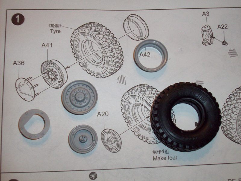


Be careful when removing the molding brace from the inside of each A42 (see review images).

When attaching parts A36 to A41, I highly recommend dry fitting them together. There are 5 ‘pins’ on the backside of A36 that line up with holes in A41 in a unique pattern. The dry fitting is important to ensure that your ‘pins’ on A36 line up with the holes correctly on A41 and to ensure your ‘pins’ all sit at the same depth in A41. If your pins don’t all sit at the same depth on A41, A36 will not sit parallel to the hub like it should.
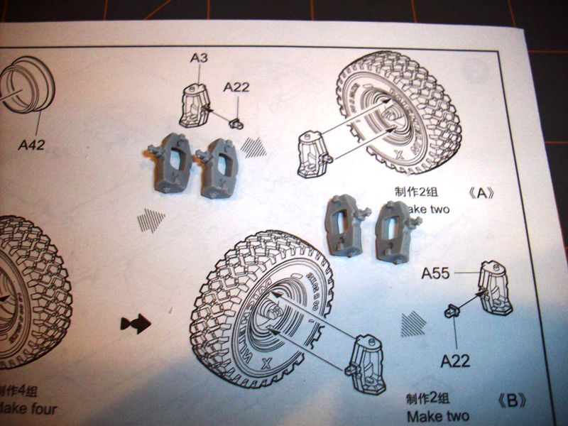
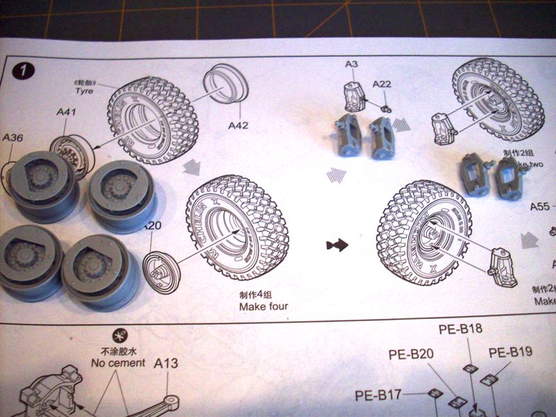


All parts in this step fit well overall. Minor mold seam clean up was required on all parts.

Step 2 This step has you assembling what I believe are transmission housings (A37, A38) and suspension arms (A12, A13). It is very difficult to tell the orientation of the suspension arms in the illustrations. I made a best guess and will find out later on in construction if I was right or not.
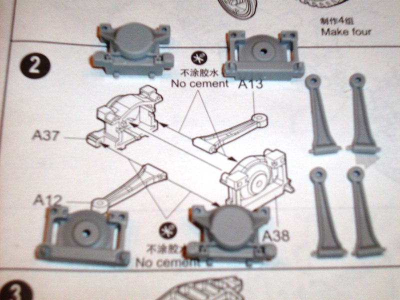


Additional detail is provide by parts A11, A1, A2 and PE B17, B18, B19 and B20. You build a total of two transmission/suspension arm assemblies in the step.
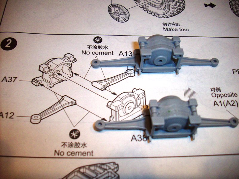
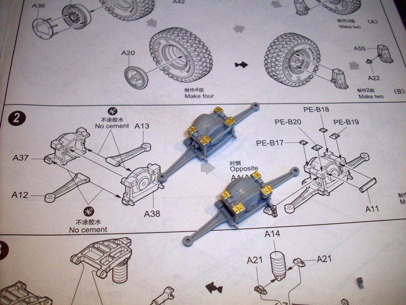


Points of confusion in this step is the lack of alignment pins in the top of either A37 or A38 to align the parts with each other. After assembly of each A37,A38 you have a noticeable gap between the existing alignment holes, but since there is not any alignment pins molded, there is a gap. Nothing a little filler won’t fix.

Step 3 This step has you assembling what they later refer to as subassembly ‘D’ which is the rear axle/drive train assembly. This step overall has to have been one of the hardest assemblies I have ever done.
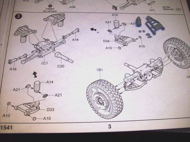
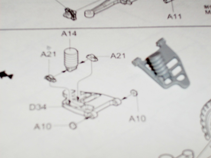
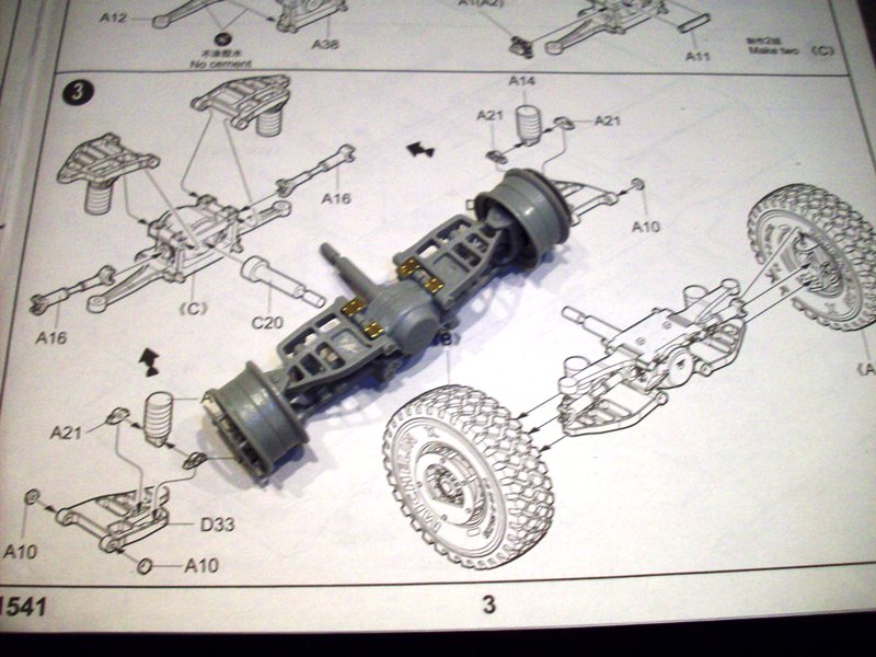


The first significant challenge was getting parts A21 to adhere in place on parts D33 and D34. For whatever reason, these parts were continually coming loose.

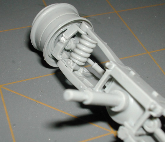
The second, and hardest, part of the assembly was getting parts A12, A13 (from step 2), parts A16 and parts D33, D34 to glue into place accordingly, and simultaneously, on the interior of the wheel hubs. There is significant movement of parts D33, D34 and parts A12, A13 during this step because they are not glued in place.

Alignment of all parts on each side while the glue is drying is challenging as well. I won’t know if my efforts are successful until Step 11 when the axle/drive train assembly is installed on the vehicle hull. The key to my success will be at the end of construction and seeing that all 4 wheels are level.

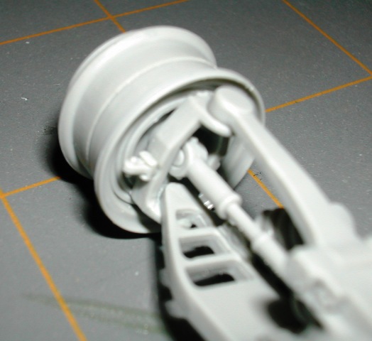
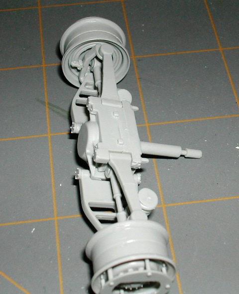
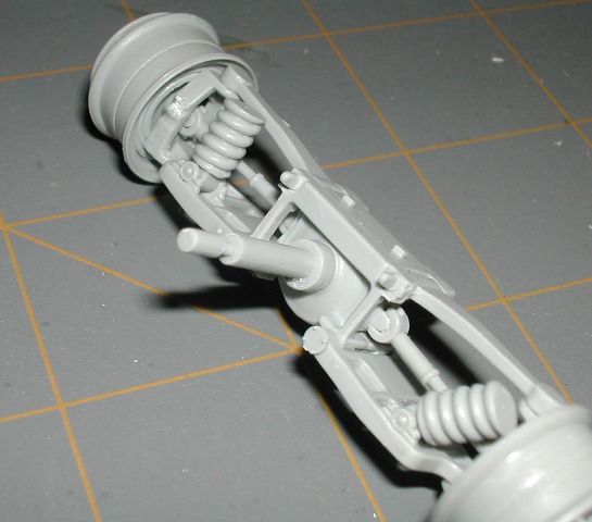
ADDED MARCH 20th AXLE DETAIL
I have had a couple of requests for closer shots of the axles due to confusion in the instruction layout. I only have one axle complete right now. After I get the second axle complete, I will come back, add more photo's and update this text. For now, here are a few closer pictures of the complete axle.


STAY TUNED.....MORE TO COME.....
35th-scale
Visit this Community
Kildare, Ireland
Joined: November 21, 2007
KitMaker: 3,212 posts
Armorama: 2,807 posts
Posted: Monday, February 22, 2010 - 09:38 PM UTC
The suspension is a fun part alright! Also, if memory serves me correctly, there was a reason what the wheel hubs are shown assembled into the tyres at construction....you may have difficulty getting them on after construction without breaking anything.....
For one of the future steps come of the small triangular PR armor plating for in the wheel arches are labled incorrectly between front and rear., Can't remember which pieces it was, but test fit all first. I think I still have the plans somewhere so should be able to look it up and provide further detail.

Cheers & Good Luck,
Sean
c5flies
Visit this Community
California, United States
Joined: October 21, 2007
KitMaker: 3,684 posts
Armorama: 2,938 posts
Posted: Tuesday, February 23, 2010 - 04:41 PM UTC
Nice start on this one Brent, your review was one of the ones that got me thinking it may be time to try something modern. I'll be watching this one with a lot of interest
sgtsauer
#065
Visit this Community
Missouri, United States
Joined: March 30, 2002
KitMaker: 2,605 posts
Armorama: 1,814 posts
Posted: Tuesday, February 23, 2010 - 04:52 PM UTC
Sean- Thank you for the information regarding the tires. I will definitely watch that potential assembly issue as I progress. Thank you also for the potential heads up on the armor plate.

James- Glad I potentially inspired someone!
shopkin4
Visit this Community
Illinois, United States
Joined: March 29, 2009
KitMaker: 1,135 posts
Armorama: 1,030 posts
Posted: Friday, February 26, 2010 - 05:32 PM UTC
I hope you know the tires are also undersized. Also, I will be watching this one in earnest. It's on my bench and part of my personal stash clearing campaign.
sgtsauer
#065
Visit this Community
Missouri, United States
Joined: March 30, 2002
KitMaker: 2,605 posts
Armorama: 1,814 posts
Posted: Thursday, March 11, 2010 - 12:49 PM UTC
STEP 4 This step covers the assembly of the front axle/drive assembly. I'm skipping this step for now and will come back to it later. I'm concerned with getting all of the parts to line up correctly so that the wheels sit level on the surface. So, I will come back to this step after Step10 and before Step 11.

STEP 5 This step has you assembling the upper hull to the lower hull. I have not completed this yet as I want to be able to seperate the upper hull from the lower hull for interior painting. I will come back to this step toward the end of Step 9 after I have assembled all of the exterior hatches and am ready to install them.

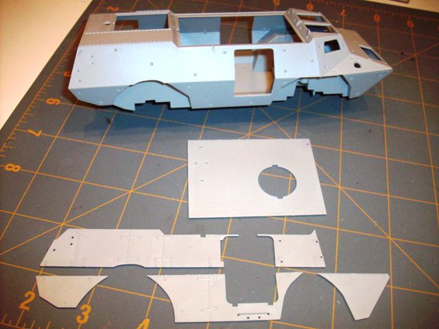
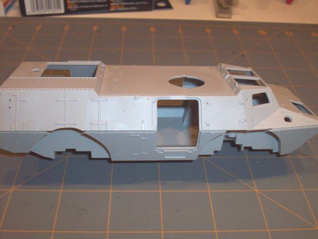
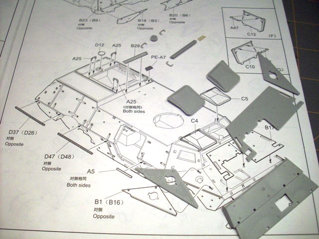
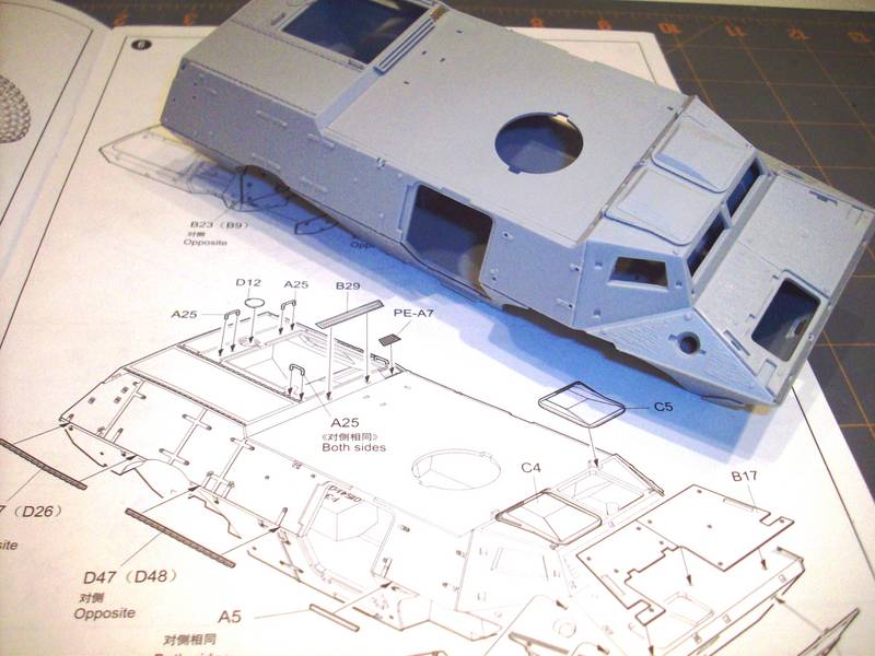
STEP 6 This step has you installing a hull roof panel (C17), various exterior armor sections, tie down strips (D26, D48, D37, D47).


A key point in this step is not trimming the parts from the sprue too close to the part. Some of the plates have angled edges where the sprue attaches to the part. If you cut the sprue to close to the part, it damages/distorts the angle of the plate edge. So, cut the part off of the sprue farther back away from the part. Then, trim the remaining sprue nub with your hobby knife so that the sprue attaching point ends up looking like the rest of the part edge.

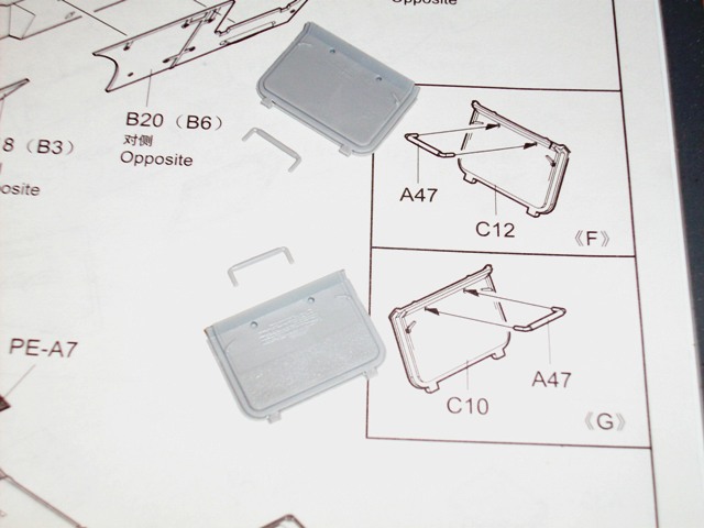
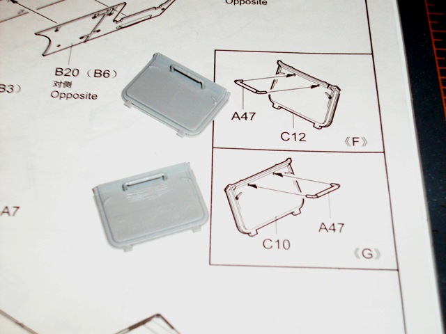
In the images below, I am assembling sub-assemblies 'F' and 'G' which are hatch sections.


Due to the fragile nature of the grab handles, I super glued them in place to ensure a stronger assembly.

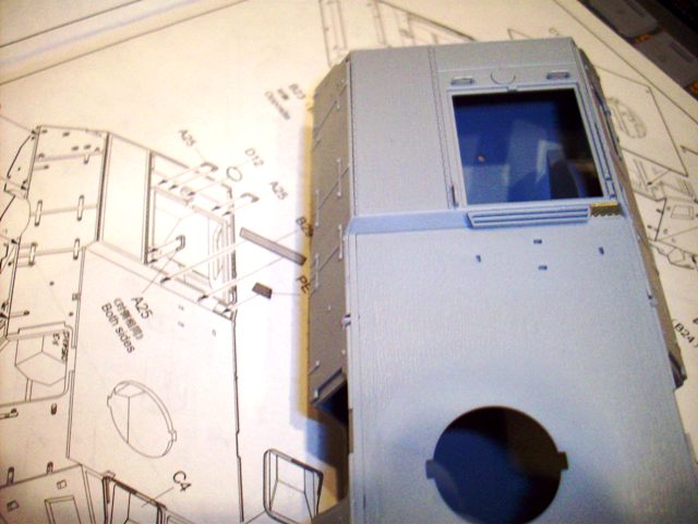
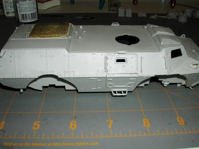
These last 3 images show the last part of step 6. In this 'sub step' you are installing tie-down strips for securing gear, front armor sections, driver and assistant driver hatches along with a few roof top attachments (grab handles, vent, etc.). I am leaving the strips of tie-downs off until after I come back and glue the hull sections together. The tie down strips fit perfectly in the gap that is left between the armor plating after the hull is fitted together.

**ATTENTION** The instructions show you installing 3 ea of part A25 (grab handle). You need to install 4 ea. of part A25. One of the parts A25 is notated 'Both Sides'. You will see it installed on my next update.


More to follow.
Herchealer
Visit this Community
Indiana, United States
Joined: July 31, 2003
KitMaker: 1,523 posts
Armorama: 710 posts
Posted: Thursday, March 11, 2010 - 12:54 PM UTC
Looking Good buddy, I may have to get one of these now. But it doesn't look like a Humvee. Do you need to go and see a doctor? Careful or may start suffering from seperation anxiety. LOL


Looking foward to seeing more.
Herky
sgtsauer
#065
Visit this Community
Missouri, United States
Joined: March 30, 2002
KitMaker: 2,605 posts
Armorama: 1,814 posts
Posted: Thursday, March 11, 2010 - 05:59 PM UTC
I got a little more done tonight. I did some jumping around in the instructions in order to get the hatch parts needed for airbrushing. I airbrushed the interior flat black as well as the interior of all the hatches. My intent, is for the interior to be too dark to be visible through the glass. I wasn't sure what else to do with an empty interior and so much glass to see through.

After I got the interior sprayed flat black, I glued the top hull to the lower hull. This enabled me to move forward with the installation of some other parts from Step 6 that I had skipped over.

One thing that has struck me as odd about the vehicle so far is the fact that the kit replicates tie down points on the right side of the vehicle but they are not replicated on the left side of the vehicle. I'm not sure if it is actually like that on the real vehicle.

One complaint that I have regarding tie down points is that the 'strips' that got mounted on the hull (D37, D47) are a little larger and better detailed than the tie down points that are molded into the top hull. Some washing and drybrushing will hopefully make them all look uniform in size.

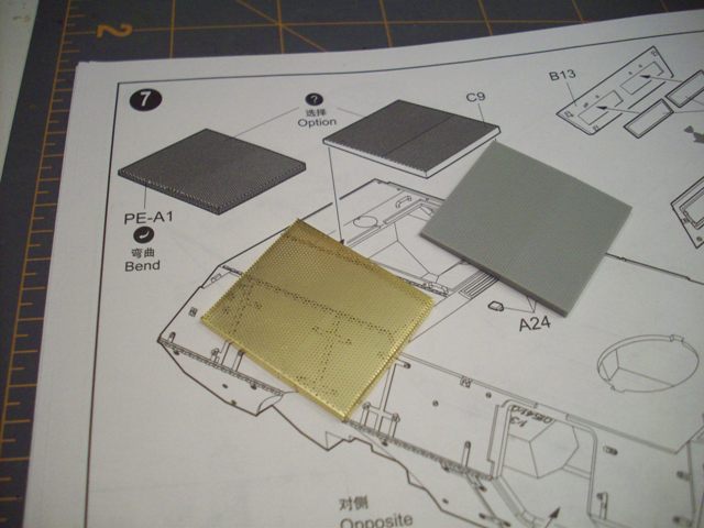
STEP 7 In this step, you assemble the windshield sections, install engine air intake screen, assemble the fuel cans and holders, and assemble the headlights.

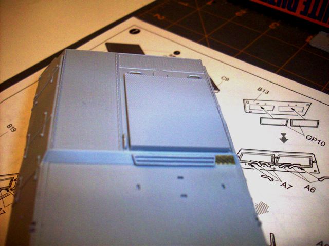
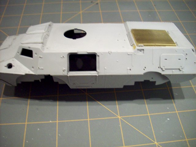
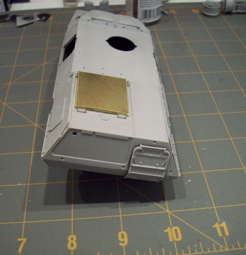
For the engine air intake screen, you can choose to use either a screen molded in styrene or you can use a photo-etch part that is included in the kit. Here is a picture of the two different screens:


Here are a couple of pictures that show the appearance of the screens dry fitted to the model.


As you can see, the PE screen looks much, much better.

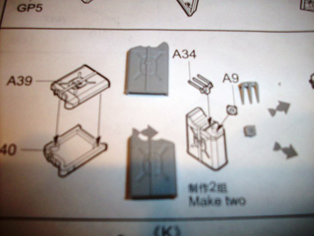
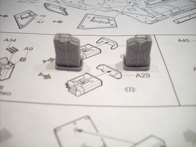
Here are couple of photo's showing the parts and construction of the two external 5 gal fuel cans. I don't like the representation of the fuel cans. The fuel cans look too much like the old metal GI fuel cans. The fuel cans we use now look different than what is represented here. The filler caps are definitely not right. Having said that, the parts are well done.


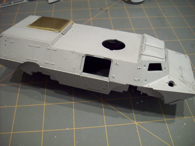
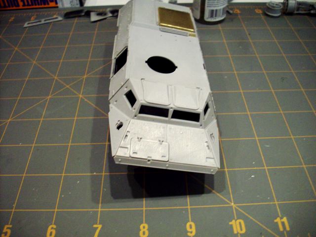
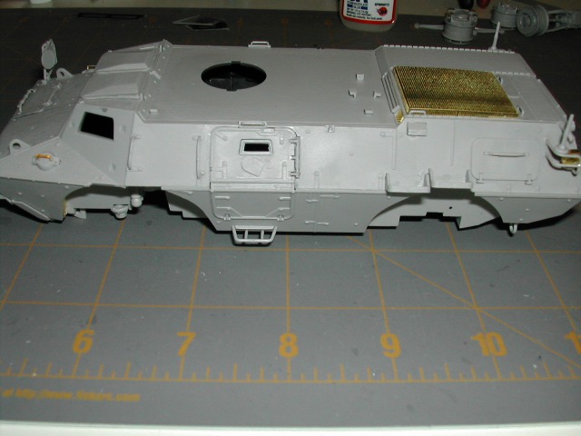
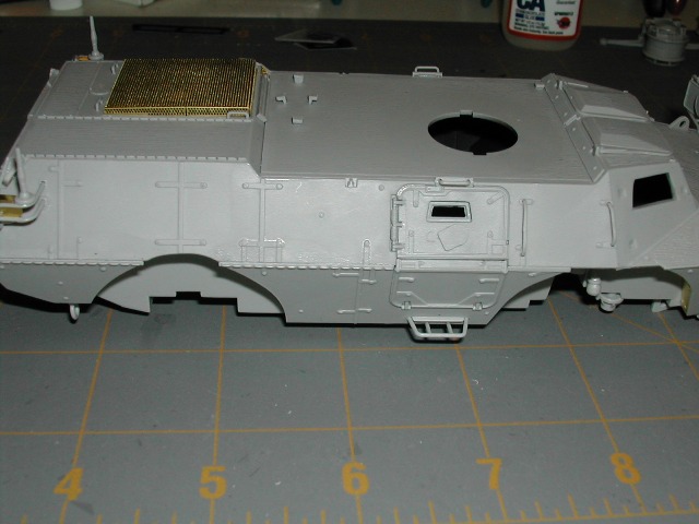
Here are a few overall progress shots I took at the end of my session tonight.


More work will be completed tomorrow.
shopkin4
Visit this Community
Illinois, United States
Joined: March 29, 2009
KitMaker: 1,135 posts
Armorama: 1,030 posts
Posted: Thursday, March 11, 2010 - 06:14 PM UTC
This thing looks like it goes together like bread and butter. Can't wait to get mine off the ground
AngryDog
Visit this Community
Singapore / 新加坡
Joined: March 27, 2004
KitMaker: 1,114 posts
Armorama: 900 posts
Posted: Thursday, March 11, 2010 - 07:17 PM UTC
Brent thanks for this build up...going to make things smoother for all of us who's going to tackle it.


Sean, you're a crazy man just like the rest of us..with so many builds. Read your post on you're ASLAVs as well... be wacthing it....wherelse I got Milo's Coyote coming ..
shopkin4
Visit this Community
Illinois, United States
Joined: March 29, 2009
KitMaker: 1,135 posts
Armorama: 1,030 posts
Posted: Thursday, March 11, 2010 - 07:45 PM UTC

Quoted Text

Brent thanks for this build up...going to make things smoother for all of us who's going to tackle it.

Sean, you're a crazy man just like the rest of us..with so many builds. Read your post on you're ASLAVs as well... be wacthing it....wherelse I got Milo's Coyote coming ..


Haha its true Nick, and thanks, but I think this will be a straight out of the box build for the M1117 with AM wheels.

Brent there are AM wheels coming out from NWM that are the correct size. I have some preproduction samples which i'll modify for my build and photograph.
35th-scale
Visit this Community
Kildare, Ireland
Joined: November 21, 2007
KitMaker: 3,212 posts
Armorama: 2,807 posts
Posted: Thursday, March 11, 2010 - 08:32 PM UTC

Quoted Text


Brent there are AM wheels coming out from NWM that are the correct size. I have some preproduction samples which i'll modify for my build and photograph.


And if you decide to wait for them I've 2 of the "A" sprue spare that came in mine instead of the "E" sprue! Loking good so far Brent.

Cheers,
Sean
woody6968
Visit this Community
England - North East, United Kingdom
Joined: March 02, 2006
KitMaker: 454 posts
Armorama: 380 posts
Posted: Thursday, March 11, 2010 - 11:15 PM UTC
hi brent , good clean build ,, i'll be following this log with interest,,keep it up
The3rdPlacer
Visit this Community
Florida, United States
Joined: July 29, 2008
KitMaker: 430 posts
Armorama: 407 posts
Posted: Friday, March 12, 2010 - 01:37 AM UTC
Brent, Looks good so far....does it have non-skid on the upper surfaces?

The pics seem to show a texture on them.

Nice set up on the build, I like your approach to modeling!

Ryan
GulfWarrior
Staff MemberCampaigns Administrator
ARMORAMA
Visit this Community
Texas, United States
Joined: January 05, 2010
KitMaker: 1,051 posts
Armorama: 1,029 posts
Posted: Friday, March 12, 2010 - 03:03 AM UTC
Brent,

Great work so far! I received my M1117 in the mail last week. That's gonna by the next one on the workbench I think. Right after the AFV Club Stryker MGS I'm hoping to start on this weekend!

Removed by original poster on 03/14/10 - 05:14:58 (GMT).
sgtsauer
#065
Visit this Community
Missouri, United States
Joined: March 30, 2002
KitMaker: 2,605 posts
Armorama: 1,814 posts
Posted: Saturday, March 13, 2010 - 05:41 PM UTC
STEP 7 continued
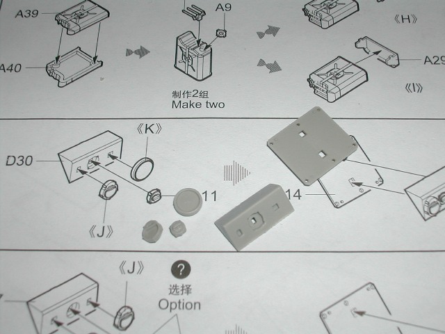
This post regarding Step 7 shows the headlight assembly.


The image above shows the part layout for the headlight assembly. This step is very straight forward and I did not encounter any issues.


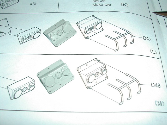
Parts D45/D46 are the headlight guards. These kit pieces are very brittle so I am leaving these parts off until I get the headlights complete and installed on the vehicle.

Since my last update, I've been working back through steps 8 and 9. As a result of my approach to assembling the model, I could not follow each step in exact order. So, as a result, the construction of these steps blended together.

STEPS 8

Step 8 has you handling several very small and fragile pieces. There are 7 grab handles and 2 towing clevis assemblies which are fragile. 2 (part A46) of the 7 grab handles are interior parts for hatch doors C1 and C2. Since my hatches are going to be closed and the grab handles won't be visible, I did not install these two interior grab handles.

Be careful removing part B27 from the sprue. It was very fragile at the base of the 'U' that goes around the rear hatch. As I cut this part from the sprue, the piece snapped in two at the base of the 'U'. I was able to reassemble the part after I got both sections installed on the upper hull.

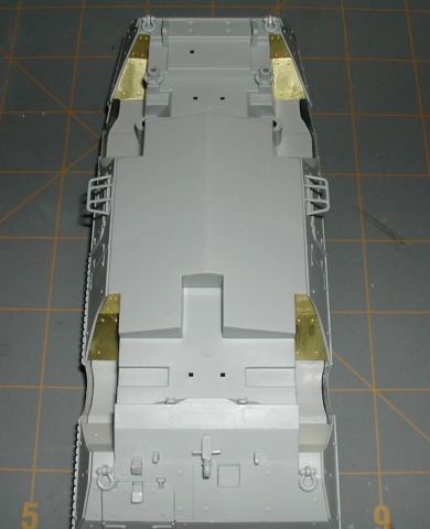
What I struggled with the most on Step 8 was the PE armor sections that are installed in the wheel wells. I had to trim parts PE-B9 and PE-B15 to get the pieces to fit in the wheel well properly. They were to wide at the narrowest point and would not fit down into the wheel well correctly.

Additionally, all of the PE armor sections have an outward 'bow' in them which prevents them from sitting flat on the wheel well surfaces like they are supposed to. I reversed this 'bow' by gently, partially rolling the parts over the handle of my x-acto knife to reverse the 'bow' and flatten the piece. I hope that explanation makes sense.

STEP 9

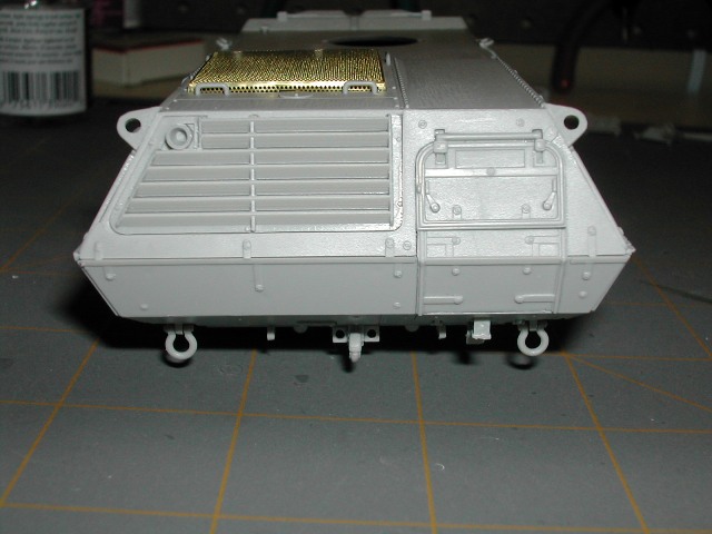
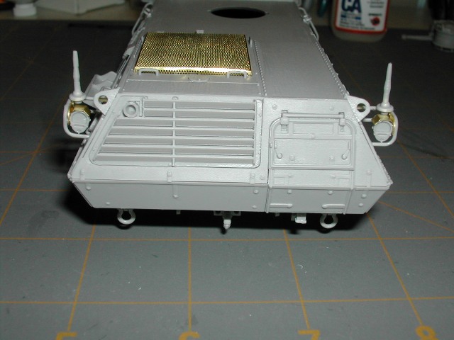
Step 9 has you installing lower, rear hull details, rear exhaust screen, a couple of exterior grab handles, fuel filler caps, PE fuel cap handles and a few other hull details.

My main challenges in this step was handling the tiny parts that go on the rear lower hull. Parts A23/A32 construct two rear towing clevises. Parts D18/A52 construct the towing pintle and parts A51 are two tie down points. All of those parts are very tiny and were difficult for my fat fingers to fumble with. I had to carpet dive 3 times before I successfully got these parts installed.

The PE fuel filler cap handles are a really nice touch and will really stand out when the kit is complete.

Other than the difficulty handling the multitude of tiny hull detail parts and having to trim down the PE armor plates that were installed in the wheel wells, I did not encounter any problems through step 8 and 9.

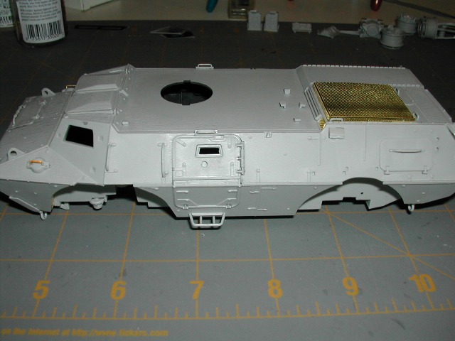
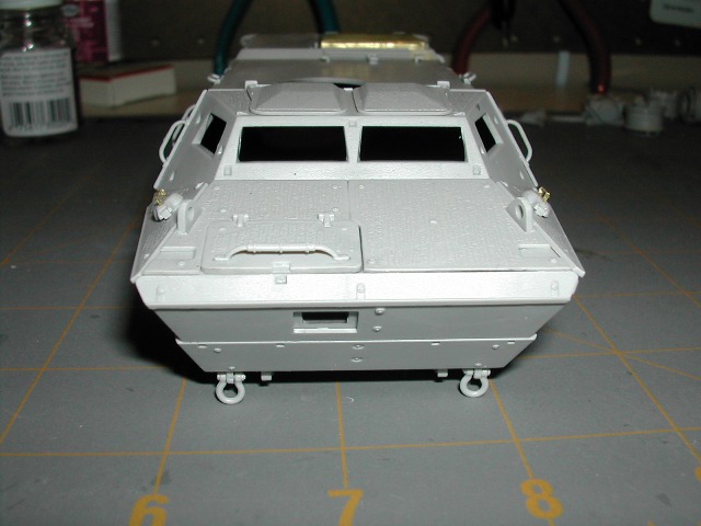
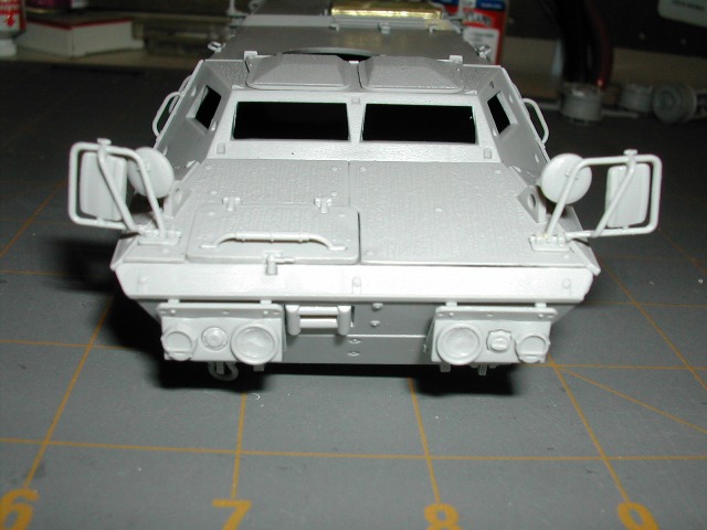
Here is the model as it appears at this point.


I'm heading off to tackle Step 10. I may post an additional update for that step tonight. I'm not sure though.
sgtsauer
#065
Visit this Community
Missouri, United States
Joined: March 30, 2002
KitMaker: 2,605 posts
Armorama: 1,814 posts
Posted: Saturday, March 13, 2010 - 07:14 PM UTC

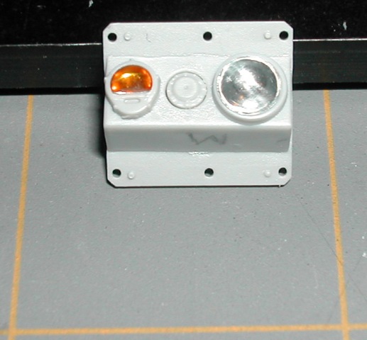
I'm working on Step 10. I was getting ready to mount the headlight assemblies to the hull when I decided to fiddle with the headlight/blinker light possibilities. So, I pulled out some MV lenses I bought the other day for just this purpose.

I think it looks promising.


The amber lense was cut down to shape with an xacto knife. Both lenses are 'dry fitted' in the image above. I had to hollow out the headlight opening some so that the concave shape of the back of lense would fit.
TankCarl
Visit this Community
Rhode Island, United States
Joined: May 10, 2002
KitMaker: 3,581 posts
Armorama: 2,782 posts
Posted: Sunday, March 14, 2010 - 04:03 AM UTC
Great build, Brent. I have finished mine a while back. Be very careful on which headlight assembly goes where. Use actual photographs, to be certain. I was able to put the tires on after I had painted the main color. I was very careful doing it, and had no problems. i did it this way, as I wanted to be sure I had a good layer of paint between the tire's vinyl, and the plastic of the hub.
GulfWarrior
Staff MemberCampaigns Administrator
ARMORAMA
Visit this Community
Texas, United States
Joined: January 05, 2010
KitMaker: 1,051 posts
Armorama: 1,029 posts
Posted: Sunday, March 14, 2010 - 04:23 AM UTC
Brent,

The lenses look really good! A top-notch job!!

I'm hoping that I'll be able to start on mine soon! I'm getting ready to be side-lined on Thursday having my rotator cuff rebuilt! No model buiding for a while it looks like!

I'm trying to get the Tamiya Bundeswehr Gepard flakpanzer done before then!

Herchealer
Visit this Community
Indiana, United States
Joined: July 31, 2003
KitMaker: 1,523 posts
Armorama: 710 posts
Posted: Sunday, March 14, 2010 - 05:19 AM UTC
Looking good Brent. Keep the good shots coming, looks like you are pretty close to some exterior painting. This blog will certainly be useful when I begin my build here in the near future. It may not be a Humvee, but hey its got for wheels and it looks cool to boot, so I guess it will suffice. Well have to chat some more on our possible combo build blog.

J
sgtsauer
#065
Visit this Community
Missouri, United States
Joined: March 30, 2002
KitMaker: 2,605 posts
Armorama: 1,814 posts
Posted: Sunday, March 14, 2010 - 04:30 PM UTC
This will be last update until sometime next weekend. I'm leaving tomorrow morning TDY till Friday.

STEP 10 This step has you installing the remaining PE wheel well armor panels, headlight assemblies, tail light assemblies, side mirrors and a few other hull details.

Unlike in Step 8, all the PE wheel well armor panels fit with no problems at all. I had to 'roll out' the curve in each panel to make it more flat. But, that wasn't difficult at all.

The next thing I did here was install the fuel can holders. The kit gives you the option of putting a section of armor plate over the hull in place of the fuel can holders if you would like. I opted for the fuel can holders. I left the fuel cans off to complete detail painting later. The holders will be painted with the body of the vehicle.

The roller bars hull insert for the winch was installed next. I had to trim this piece up a little bit, but overall its fit was fine.

My first struggle was the assembly of the tail lights and the guards that the tail lights mount on. Each assembly comprises of 5 pieces not counting the lense. The guards(D51, D52) that the tail light mounts to are very brittle. Handle these with care. I snapped one in half and spent almost an hour repairing it. The mounting lugs for the tail light body are undersized and made it difficult to accurately mount the tail light body to the PE mounting plate(PE-A6 x2). Super glue and accelerator ended up being my friend here. PE parts PE-A5 are light covers in the tail light assemblies. I had to trim about 1mm of the 'mounting side' of each piece where it touches the PE-A6. PE-A5 was just to wide to fit properly if I had not trimmed it.

My last battle in this step was the assembly of the side mirrors. The kit lets you chose from two different designs. The parts that comprise of the frame work for the mirrors is very fragile. Take your time here and handle with care. I had to use super glue with accelerator to get the parts installed properly. There just isn't enough surface area on the parts for traditional model glue to adhere properly.

Headlight, marker light and tail light lenses are being left off until after painting/detailing has been completed.

Here are photos of the model at the end of Step 10.


My next installment will be Step 12 and 13 which covers the construction of the turret and armament. I will be able to return to the 'step-by-step' process that I was trying to follow at the beginning of this blog.

Till next time....Take care and build something!!!
m75
Visit this Community
California, United States
Joined: July 20, 2002
KitMaker: 666 posts
Armorama: 661 posts
Posted: Tuesday, March 16, 2010 - 03:03 PM UTC
Yeah, the tailight guards guards were not my friends here. I broke the top rail from the right side and had to substitute a short length of Solder (which worked out great, BTW). I too had a challenge in determining just how to make the light body and shield fit together, and decided that superglue and accelerator (and a lot of luck) was my ticket on this part. Came out fine.

Havoc, I am SO looking forward to getting some paint on this when the military missions die down after early April.
CaptGrim
Visit this Community
Texas, United States
Joined: March 16, 2010
KitMaker: 7 posts
Armorama: 5 posts
Posted: Tuesday, March 16, 2010 - 03:19 PM UTC
Great looking model! I will be following this one very closely. I am an intermediate model builder and I have just started really getting in to high level detail and weathering.

I notice everyone on this website builds almost the entire model before painting. I have never thought of it before but it seems to work really well. Please keep the pictures and info coming I am learning a ton from this.

Appreciate the work you are doing thanks!
sgtsauer
#065
Visit this Community
Missouri, United States
Joined: March 30, 2002
KitMaker: 2,605 posts
Armorama: 1,814 posts
Posted: Tuesday, March 16, 2010 - 03:54 PM UTC
Jim, I hate to say it but I'm glad to hear that I'm not the only person who struggled with the tail light assemblies.

Miguel, thank you for your compliments.

I consider myself to be an intermediate modeller. This is my first time truly using PE on a model. I've put more PE on this model (all included in the kit) than I have any other model. I'm certainly getting some valuable experience in that arena.

In regards to assembly/painting, I always do as much assembly as possible prior to cranking up the airbrush. For me, assembly is more difficult if I do a majority of painting first. This is because the paint interferes with the glue adhering parts together and things don't want to stay assembled.
 _GOTOTOP