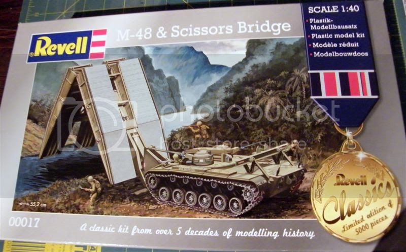
This represents a model of the original V12 air-cooled petrol engine M48 slick with a 40 foot Scissors bridge, & at best represents the MK1 or even prototype tank/bridge combo, so couldnt be used as a modern example, which usually fields a 60foot bridge (2of, 10 extensions added to the middle.)
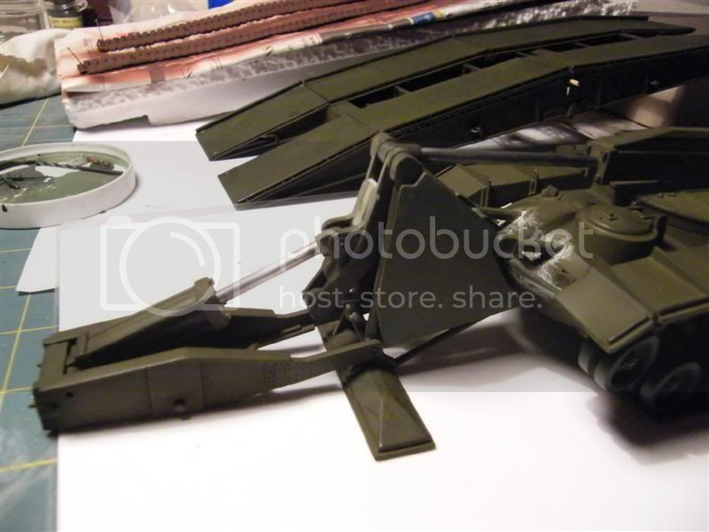
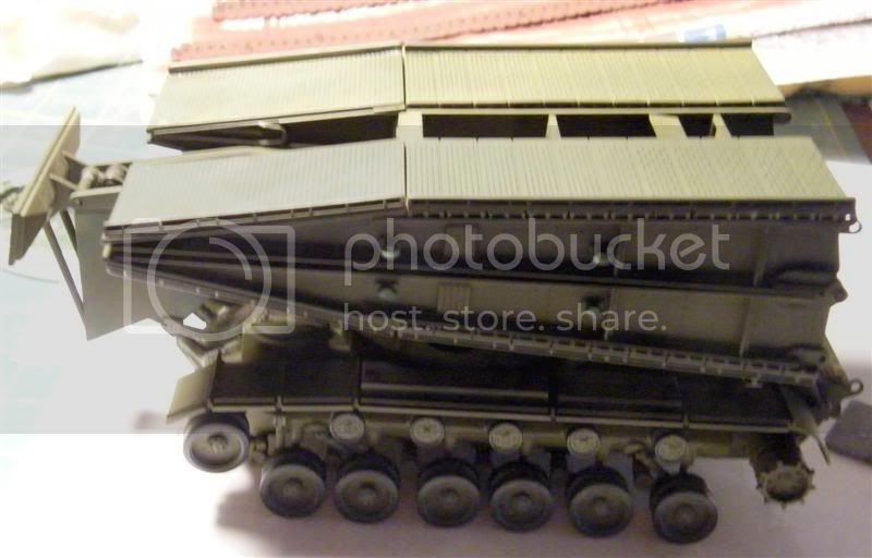
Its also 14.3% smaller than 1/35th scale & the difference is noticeable, see pics, but Tamiyas M48A3 could just about pass over the bridge.
The box strapline of "A classic kit from over 5 decades of modelling history" means © 1959, with 1982 & 2009 releases, of which this build is an example.
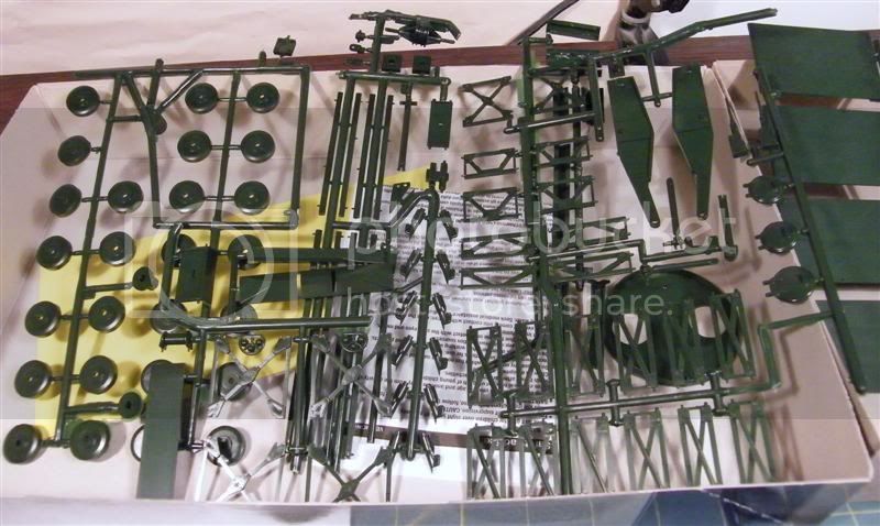
The traditional HISTORYMAKERS box, sturdier than the usual end-opening Revell offering contains:
Some 100-odd parts, some very odd! If youve seen the green figures in Toy Story, you will know what I mean about the 4 supplied figures.
1 metal spring & 2 rubber tracks.
An 11 page instruction sheet that needs careful reading, some of the 52 stages are not at all clear, so this is not a kit to be rushed.
Impressions
For a 52 year old, its in very good shape, but more Joan Collins than Carol Vorderman. (Thoughtful pause for Brits here, otherwise Google is your friend!)
As a 52 year old, words like accurate, shakenbake & simple arent appropriate, but as I write Part 1 (60% complete) its fun, so far.
Lots of flash to be removed, but not too bad.
The Build
Parts Terminology is mine, and/or in English, & shouldnt be confused with official US Army Terminology. (Step numbers in brackets like this) [US equivalents like this]
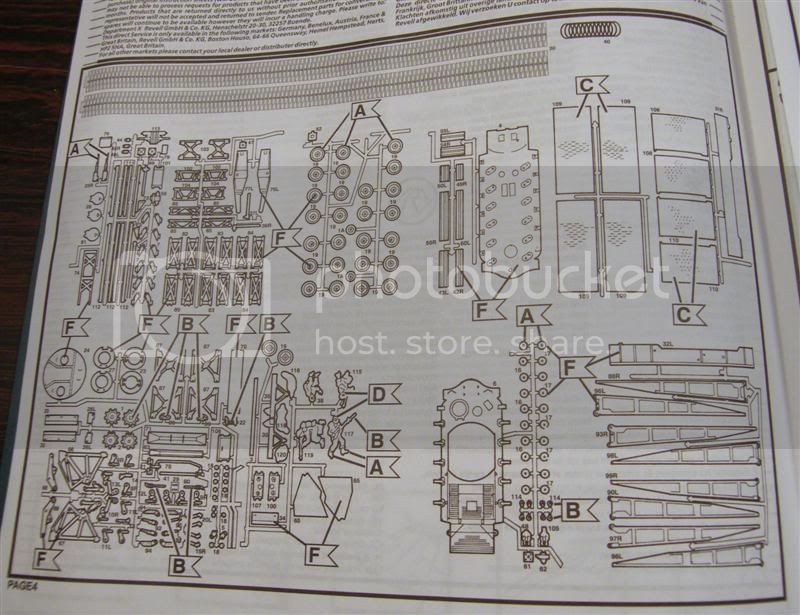
Layout page 4 & keep this to hand as this contains a drawing of the sprues, then layout the parts to match, essential as if anyone has tried to shakenbake the box there will be a lot of loose parts.
Luckily, many of these parts will have their part numbers on them (g).
This build can be treated and built in 3 sections, the hull/running gear, plumbing with scaffolding, & the bridge itself.
Consider separating the parts sprues into the 3 sections as this will help with parts finding.
I always paint as I go, & considering the intricacies of the bridge, this is recommended.
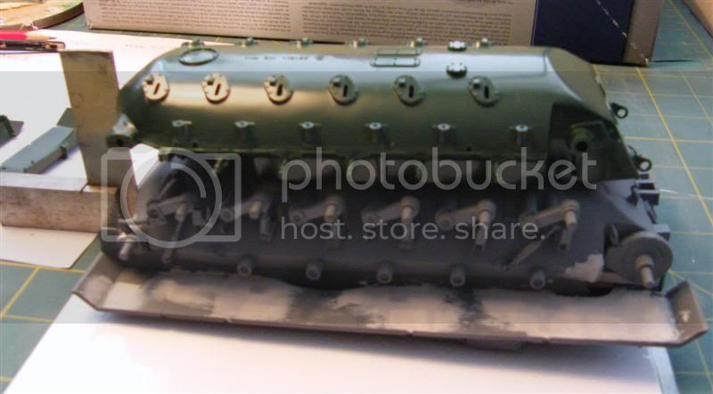
The Hull, (1-17)
No real difficulties here, but a lot of small flash to be removed.
Clean up the parts needed in each step, removing the part numbers as you go, (if you feel like it) & tack the part to the hull with small amounts of liquid glue, then glue more securely when complete & properly lined up.
I usually start by gluing the hull together anyway (1, 2), adding about 100g [3 1/2oz] of lead to balance the 100g of bridge.
Fill any gaps & the big dimple under the noses chin. I recently discovered Acrylic knifing putty from Halfords, [similar to 3m Blue putty?] This sands very smooth if done wet.
Then tack the suspension pivots first (3) before tacking the suspension arms, one side at a time (4, 5)
Use a small straight-edge to make sure they line-up fore & aft, & top to bottom, so that the holes are straight & level, & brush the joints together using liquid glue.
Make sure you sand the dimple on the end of the return-roller arms errr, round(er), they have a prominent seam that is hard to sand with the fenders on. This makes the fit quite loose so after painting I glued them on with PVA [Elmers]
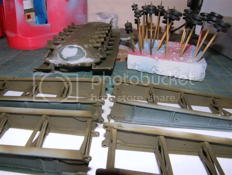
Lots of clean-up in the wheels (7-10) make sure you have lots of cocktail sticks.
A Dremel & boss mounting would be useful here, as would a chunk of 3M green pot scourer.
I then sprayed the hubs, & usually hand-paint the tyre part, I find that easier, but dont add the wheels until final sub-assembly.
Add part 24, turret blanking-plate (11-12) to the hull, & assemble the MG turrets, but dont add, as they click into position & can be added later.
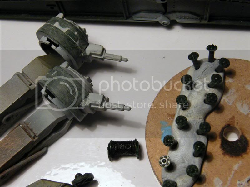
These are frankly awful to sand, as the top & bottom parts are ovoid, & the vision blocks are on the seam line, which may or may not be correct. Replace the .50 cal mg barrels, I kept snapping them off during sanding!
Consider removing the vision blocks entirely to sand round, then adding them back. Or Not.
I havent seen any photos of this type of cupola & later M48/M60 AVLBs have a different style, as here: https://aeroscale.kitmaker.net/forums/155137" TARGET="_blank">
https://aeroscale.kitmaker.net/forums/155137
I havent found any refs or pictures for the MG turrets, & these may only have existed on the prototype and/or only in the drawings. Someone may know better & help out here.

I didnt consider AM parts here, as they wouldnt fit anyway, (pearls & swine, etc.)
The mud-guards/[fenders] (14-15) have ejector-pin marks at either end of the transverse ribs. Clean up or not (guess what I did.
 )
) The turret blanking-plate was added first, as I used it to help align the fenders. These can be bent slightly up then snapped into the locating lugs before gluing in, (with liquid glue.) Make sure you keep the fenders pressed level with the engine deck, mine wanted to stand higher than that.
Steps (16-17) cover small parts, driver & bridge rest, cleaned up, painted separately & put to one side.
Plumbing (18-37)
Lots of Gotchas here, go carefully & read ahead, turn the page over & study steps (32 to 37)
Guess why.
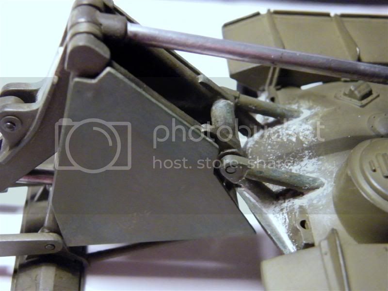
Step (18-21) Bridge piston with spring
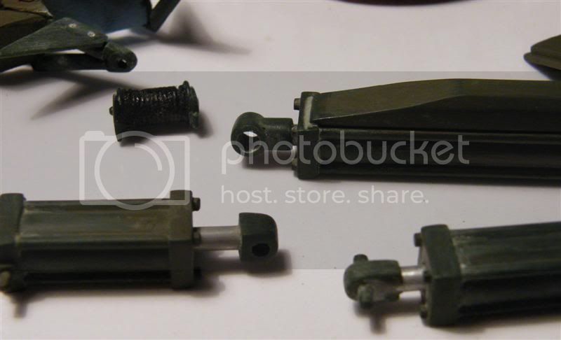
Step (22-27) the pistons, lots of fettling needed, do one step at a time, its easy to mix them up.
The end pivots are different, so be careful. Drill out & replace with something stronger & straight!
The piston parts are confusing & are very loose in the piston barrels. They look very over-scale and as circular as a running-track round the football field.
A simple fix would be to sleeve the pistons with metal tube to simulate the chromed rods.
This would take some of the whip out of the assembly, but wouldnt solve the problem of the rods coming loose from the barrels, see below.
Being awkward, I replaced the piston bits (parts 53, 58 & 64) with aluminium rod, [AL-yew-MIN-ee-əm], with the end turned over like a button mushroom. The barrel parts (steps 22 to 27) are knarly inside & need to be reamed out, or lined with a wider tube for the piston end to run in.
Of course, I decided to do this after Id glued all the bits together.
The piston end caps (parts 47, 52, 57, & 6) are too sloppy & the opening needs to be lined with a tube.
Since I didnt have any to suit, I wrapped a strip of Post-It paper round the aluminium rod STICKY SIDE out until it was a snug fit in the end caps, then carefully unwrapped it & super-glued it like a Swiss roll, rolled back up & passed it to the end-cap, all the while spinning the ali rod to stop it sticking to the super-glued paper. Trim when dry.
My next problem after that (!) was that the ali tube I used was the same diameter as some of the end pivots. In the end, I reduced the diameter of the end of the ali rod, using a file & a battery drill as a lathe...
Scaffolding (28-37)
The major framework (28-33) parts are cleaned up, test-fitted, & pre-painted, but not assembled yet.
The cover plates (p.65x2) are symmetrical, fill the ejector-pin marks before painting. Leave off until all the plumbing & pistons are fitted, it makes it waay easier.
Warning 1: It took me a while to figure out that the cross-rods (on part 66) are more conical than parallel & if not attended to or replaced, the whole scaffolding assembly (28-37) will have a definite lean & nothing will sit straight!
Warning 2: The piston from step (25) needs to fit in step (31) AND also step (36). Fit it to step (36) first, or it wont go in!
Alternatively, drill out all the pivot points & replace, as if you are in clumsy mode, theyll break anyway.
Assemble Scaffolding & Plumbing parts using steps (32-37) as a guide. Make sure the chassis is complete with track before adding the pivots parts 72-73 to hold the scaffold flat to the floor & square everything up before gluing parts 72-73 to the chassis. Add braces, parts 73, & other small parts.
I replaced the hydraulic pipe (78) with leftover PVC tube from a motorbike kit.
The Bridge (38-49)
This is where the parts layout comes in useful, with lots of ironwork with the merest of differences!
I found a flat sharpening stone handy, along with riffling & flat files, wet & dry etc., and a PENCIL.
LOTS of cleanup, inc. cast-in parts numbers.
I wrote the parts & stage numbers on the outside edges of the bridge leg webs, just to be able to keep track.
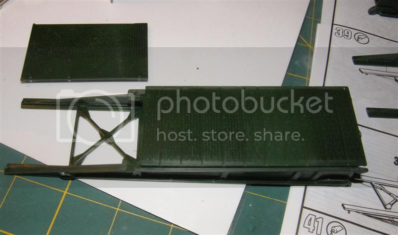
Example build: (38)
Remove parts 82 to 88 & lay them out exactly as per the instructions.
Clean up as required, & test fit each cross-web (82-87) against both legs. These parts have pegs that fit into the legs & should fit one way only! Trim the pegs slightly so that the frames sit flush both sides.
Caution! The X shape (p.87) CAN be fitted the WRONG way round!
Assembly: Tack the frames to one side of the leg, then tack to the other side.
I used the bridge floor parts (p.108-109) to hold it true while clamping with pegs, then brushed the frame joints with liquid glue, taking care not to glue the floor parts to the legs & frame.
Repeat for steps (39, 41 & 42), using the floor parts (p.108-110) to hold the parts true while drying.
Get each ¼ part as straight & as flat as possible.
Steps (40, 43)
Dont hinge the 4 bridge quarters together, TRUST ME!
If you do, you will need at least 3 or 4 hands for steps (44 & 45)
Dont decide replace the missing hinge pins on the inside edge, as I didnt consider step (48) & part (p.113)
At this point, I pre-painted the 4 bridge quarters insides & floor plates underneath, take care not to over-paint the pencil numbers, this will make handling easier.
Joining the Quarters. (44, 45, 46 & 48)
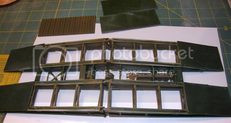
Layout the 4 bridge quarters, & clean up cross supports, parts (p.102-107, & 113).
If built as per instruction steps, the bridge halves wouldnt lie flat when folded. This could just be my sloppiness, or the kits age. If I did this, or similar again, Id drill out the pivots, & re-pin.
There is no easy way to do this.
If you go as per instructions, (38+39 then 41+42) you end up with 2 long unwieldy bits to join with 9 cross-pieces. Use a square to get the cross frames lined up at 90 degrees.
If you join front & rear Halves, you get wide & unwieldy parts to join. Have fun & dont forget part 113! Be careful in steps 45/46, you need to pass the piston from step 21 through the frames. Glue securely.
Step 49
I knotted 2 lengths of black thread, then cover with super glue to get rid of fuzz & to strengthen the thread.
Pass this through the eyes in part 105, pass over the grooves in part 113, & through the eyes in part 48, pull as tight as you dare to take the slack out, but not too tight, knot & glue. The wire ends are terminated to large pad-eyes, similar to tow rope eyes, so a bit of judicious blobbing isnt amiss here, paint blob dull silver.
Be careful with thread tensioning, as when you fold the bridge, the piston acts as a spring to help with the unfolding, & if too tight, it will pull the joints apart.
Bringing it all together
Place finished hull with tracks on a secure flat surface.
Offer up completed scaffolding pivots parts 72, from step 34.
Get the foot of the pivot as flat & straight as possible, then glue parts 72, then supports, parts 73, to secure.
Other small parts are covered in the final steps.
More build pics here: http://s70.photobucket.com/albums/i88/jon_a_its/M48%20AVLB%20Blog/
Stick a fork in in it!
I'm allowing this to 'rest' before decalling.
https://aeroscale.kitmaker.net/forums/155137