

Once again, our AMPS chapter is doing a group-build. This time our subject kits are actually photo-etch up-date sets from Alliance Model-Works with the club members selecting from several DML Panther Ausf. G-series Smart Kits that the PE sets will work with.
We've done this in order to give guys some practice working with more than just the simple PE parts that are included in the kits. We started this build off with a meeting night demo on using PE and soldering, and purchased our kits in bulk wich saved us considerably over individual purchases.
Alliance Model-Works has graciously donated the PE sets for this build to our club, so before going any further, I want to give a them a big thanks! This was a very generous offer on the part of Brian (the "BrassNautilus") and his associates, and one that we really appreciate!
The beauty of this is that it gives a good number of our members an opportunity to work with a "full up" PE detail set that includes several rather complicated assemblies and expand their skill-sets without having to take big risks by going it alone with more PE than they're otherwise used to working with.
The PE sets that we're using have been recently reviewed here on Armorama, so I'd encourage anyone interested in them to check out these links:
AM-Works PE Set for DML Panther G
AM-Works PE Set for DML Jadgpanther
We have some additional build notes, reference information, and member group-build photos on our club website:
AMPS Central SC Group-Builds & Demos Page
All of our group-build notes are available to down-load, so feel free to use the information if you find it useful.
In my next post, I'll explain my own project Panther...
Hosted by Darren Baker
DML #6370 Panther Ausf. G with AM-Works PE
SdAufKla

Joined: May 07, 2010
KitMaker: 2,238 posts
Armorama: 2,158 posts

Posted: Tuesday, September 27, 2011 - 08:04 AM UTC

shopkin4
Joined: March 29, 2009
KitMaker: 1,135 posts
Armorama: 1,030 posts
Posted: Tuesday, September 27, 2011 - 08:30 AM UTC
I actually just bought 6268, Dragon's Panther G with the rear steel wheels, AM Works Panther stuff and an Aber Barrel. I'll start it as soon as I get it and will be subscribing to this as well.
SdAufKla
Joined: May 07, 2010
KitMaker: 2,238 posts
Armorama: 2,158 posts
Posted: Tuesday, September 27, 2011 - 08:37 AM UTC
For my build, I selected the DML #6370 Panther G w/ Steel Raod Wheels. This kit has been been out for some time and reviewed in several locations, so I won't bore you with all of the "in the box" review-type comments.
It's a very nice kit, though, and includes all of the optional parts need to buld just about any Panther Ausf. G variant. About the only thing that would keep you from building ANY Panther G is that the turret does not have the horseshoe-shaped opening in front of the commader's cupola for the IR device connection to the gunner's elevation indicator. Other than that, the kit includes both rubber tired and steel rimmed road wheels, standard and Flammvernichter exhausts, optional MG ball mount openings, optional parts for early and later engine deck details, and on and on. Like I said, a very nice kit....
In fact, the only real problem that this kit has is that IT"S OUT OF PRODUCTION! (Come on DML - What's up with that?!) We actually had quite a bit of trouble roundng up enough copies of this kit for the guys in the group-build that wanted to use it.
Of course, it is a DML kit, so the instrucitons do leave a bit to be desired, especially in the area of all of the available optional parts. I highly recommend the Panzer Tracts 5-3 as a reference to help sort out all of the various parts that can be used.
Our group-build notes do cover quite a number of these options, though, so if you're building any one of DML's Panther G Smart Kits, check out our notes and maybe save yourself some headaches!
In addittion to the DML kit and the AM-Works PE, I'm also using the Aber main gun and MG barrels and Fruil tracks. As I was planning my build, very early on I decided to avail myself of the potential that the DML semi-workable suspension affords and display my Panther with articulated wheels and tracks, and the Fruils make this much easier and flexible (no pun intended) when basing the model.
I started my build with the AM-Works PE front fenders. These are very nice and allow some nice options like battle damage when built. Our PE demo notes offer some suggestions in the sequence of assembling these.
I've elected to show the left front fender in a damaged condition on my model, and here is where soldering the PE really stands out as a building technique. The solder joints are strong enough to withstand the force involved in realistically "smashing" things up, and my front fender was no exception.
For soldering, I use a micro-torch and various high and low temp solders along with heatsinks (usually nothing more than a bit of wet paper towel). These resources will allow you to do some pretty slick things once you practice a bit.
My next sub-assemblies were the PE rear stowage boxes. Again, our build notes offer some suggestions on the assembly sequence here. However, the PE mounting brackets and lid latches can just as easily be used on the plastic kit boxes to improve their appearance.
If you don't desire to show the boxes open or damaged, then dolling-up the kit parts with the PE details offers a nice middle-ground option for your build.
So, in my usual practice, I'll stop here and just say "more to follow"...

Tankrider
Joined: October 07, 2002
KitMaker: 1,280 posts
Armorama: 1,208 posts
Posted: Tuesday, September 27, 2011 - 08:57 AM UTC
That is some exceptional PE work, Sarg'nt Major... Nice clean solder joints. I need to try the wet paper towel trick as a heat sink on my next PE endeavour.
John
John
SdAufKla
Joined: May 07, 2010
KitMaker: 2,238 posts
Armorama: 2,158 posts
Posted: Tuesday, September 27, 2011 - 09:11 AM UTC
I guess that I should say here, that building the more complicated PE sub-assemblies first is my usual sequence. This way I know before I start making un-alterable changes to the kit or its parts that I have acceptable PE assemblies.
Also, many of your PE assemblies will require modifications to the kit, and you need these already built in order to dry-fit and make the necessary kit changes. So - I build most of the PE up-front... anyways... back to the model...
My next sub-assemblies were the PE tool racks. For the sake of keeping the straight, I'll call these tool rack "A," "B," and "C." This is just for convience of discussion and has nothing to do with the actual German designations.
The first thing needed to build the tool racks were the tool clamps. I've commented on a couple of other threads just how neat I think the AM-Works tool clamps are. Here's a couple of happy snaps of these:
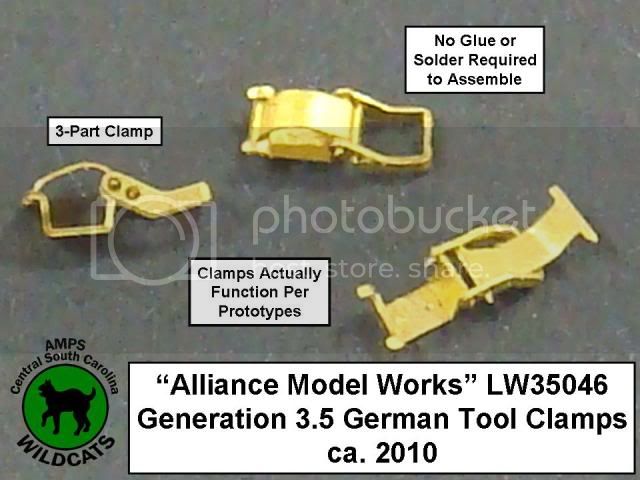
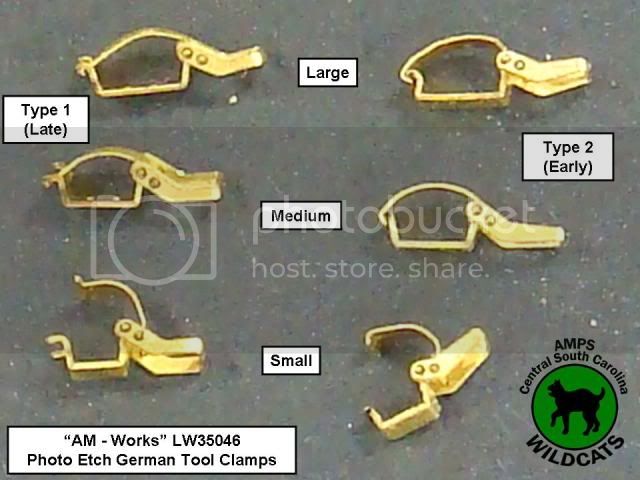
One of AMPS club newsletters has an article that discusses these clamps as compared to some others on and off the market:
The Wildcat Vol. 2 No. 8
Once I had enough clamps built, I then removed the molded on tool clamps from the kit's plastic tools. This gave me the tools needed to dry- and test-fit the PE parts as I was assembling them to ensure that the tool spacing and layout was corrrect.
Here's tool rack A:
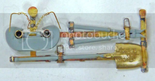
Tool rack B:
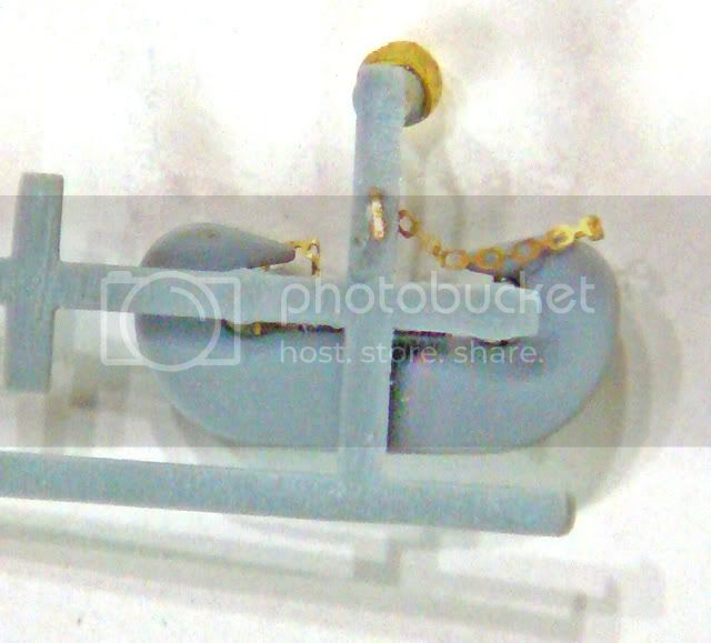
Note that here I had to scratch-up a new starter crank handle. I believe that the AM-Works PE parts are essentially correct (when compared to the Panzer Tracts 5-3 plans) and that the DML handle is off a bit in its dimensions. At any rate, I couldn't fit the kit handle in the tool rack and get it to look right.
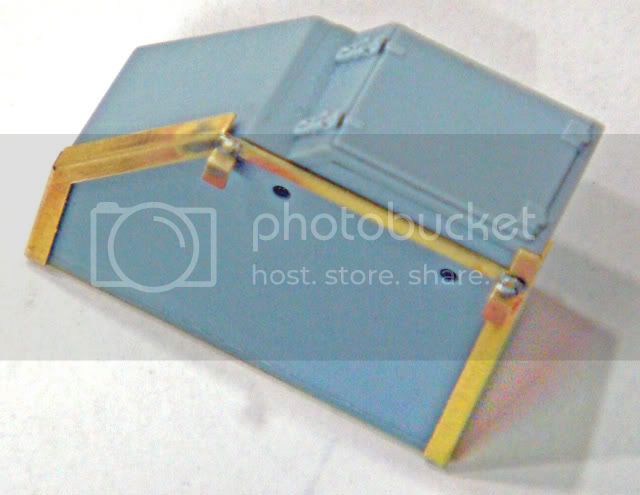
Here's tool rack C:
Note in the photo here that I'm just dry-fitting the tools and the right-hand clamp assembly has slipped a bit. I'll add the tube that holds the track-tension wrench when I put the rack onto the hull. For this tube, I'll use a piece of hypodermic needle. (Same for the track changing cable mounting tube.)
Here's the jack block rack:
This rack is a great PE assembly to test your soldering skills on since the two solder joints are wide apart and the parts can be clamped quite tightly and easily!
Finally, as with the rear stowage boxes, the kit's plastic tool racks can also be detailed out with PE parts to enhance their appearance. Here're are a couple of photos of the kit tool rack A that has been thinned down by sanding, drilling out the clevis mounting tubes, and adding a couple of left-over PE parts (spare parts that come with the PE up-date set).
You can see in the second photo that I drilled a small mounting hole and used the PE fret attachment point on the keeper chains as a "gluing pin" to add strength to the glue joint.
More to follow...
Also, many of your PE assemblies will require modifications to the kit, and you need these already built in order to dry-fit and make the necessary kit changes. So - I build most of the PE up-front... anyways... back to the model...
My next sub-assemblies were the PE tool racks. For the sake of keeping the straight, I'll call these tool rack "A," "B," and "C." This is just for convience of discussion and has nothing to do with the actual German designations.
The first thing needed to build the tool racks were the tool clamps. I've commented on a couple of other threads just how neat I think the AM-Works tool clamps are. Here's a couple of happy snaps of these:
One of AMPS club newsletters has an article that discusses these clamps as compared to some others on and off the market:
The Wildcat Vol. 2 No. 8
Once I had enough clamps built, I then removed the molded on tool clamps from the kit's plastic tools. This gave me the tools needed to dry- and test-fit the PE parts as I was assembling them to ensure that the tool spacing and layout was corrrect.
Here's tool rack A:
Tool rack B:
Note that here I had to scratch-up a new starter crank handle. I believe that the AM-Works PE parts are essentially correct (when compared to the Panzer Tracts 5-3 plans) and that the DML handle is off a bit in its dimensions. At any rate, I couldn't fit the kit handle in the tool rack and get it to look right.
Here's tool rack C:
Note in the photo here that I'm just dry-fitting the tools and the right-hand clamp assembly has slipped a bit. I'll add the tube that holds the track-tension wrench when I put the rack onto the hull. For this tube, I'll use a piece of hypodermic needle. (Same for the track changing cable mounting tube.)
Here's the jack block rack:
This rack is a great PE assembly to test your soldering skills on since the two solder joints are wide apart and the parts can be clamped quite tightly and easily!
Finally, as with the rear stowage boxes, the kit's plastic tool racks can also be detailed out with PE parts to enhance their appearance. Here're are a couple of photos of the kit tool rack A that has been thinned down by sanding, drilling out the clevis mounting tubes, and adding a couple of left-over PE parts (spare parts that come with the PE up-date set).
You can see in the second photo that I drilled a small mounting hole and used the PE fret attachment point on the keeper chains as a "gluing pin" to add strength to the glue joint.
More to follow...
SdAufKla
Joined: May 07, 2010
KitMaker: 2,238 posts
Armorama: 2,158 posts
Posted: Tuesday, September 27, 2011 - 09:17 AM UTC
Quoted Text
That is some exceptional PE work, Sarg'nt Major... Nice clean solder joints. I need to try the wet paper towel trick as a heat sink on my next PE endeavour.
John
Thanks, Sir! I find it more productive than "whippin' the eff'ing rose bushes into shape!"

SdAufKla
Joined: May 07, 2010
KitMaker: 2,238 posts
Armorama: 2,158 posts
Posted: Tuesday, September 27, 2011 - 09:52 AM UTC
The next really "fiddly" PE bits make up the gun cleaning and spare antenna stowage tube.
The most difficult task here is to roll the flat PE part into the tube shape. The best advice that I can offer here is to just be patient and take your time (duh!).
I used several different soft surfaces (from a piece of 1/4"-thick foam core to several sheets of paper) and different sizes of rollers (brass rods, X-acto knife handles, etc). One thing to note on the AM-Works part is that it is designed to have a lap-joint on the long edge, so when it's properly formed, the joint is nearly invisible. Also, anneal the metal before trying to roll it.
Here's a collage of a couple of different views of my stowage tube:
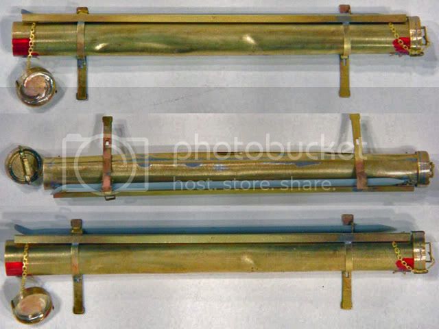
The AM-Works tube caps are made by assembling several rings and a flat disk to which the handle and keeper chains are added. I used three rings on the open end of my tubes, but after looking at the things for a while now, I'd suggest using only two so that they're not so deep.
Here's a good place to experiment with different temp solders. I used a "high-temp" silver solder (450 degrees) on the rings and disks and a "low-temp" solder (275 degrees) on the handles. The low-temp solder (Tix) only needs a "whiff" of heat from the torch to melt. As soon as it does, remove the heat to keep from un-soldering the other joints.
Again, the solder joint is strong enough to withstand the "damage" I inflicted on my tube using my thumb nail. I'm also planning on showing some of the cleaning rods sticking out of my stowage tube on the finished model.
Finally, although I didn't take any pictures, the plastic kit tube and caps will fit the PE mounting brackets (the plastic tube will need some filler). If you're not planning on damage or having the tube open, the plastic tube with PE details will look pretty good.
More to follow...
The most difficult task here is to roll the flat PE part into the tube shape. The best advice that I can offer here is to just be patient and take your time (duh!).
I used several different soft surfaces (from a piece of 1/4"-thick foam core to several sheets of paper) and different sizes of rollers (brass rods, X-acto knife handles, etc). One thing to note on the AM-Works part is that it is designed to have a lap-joint on the long edge, so when it's properly formed, the joint is nearly invisible. Also, anneal the metal before trying to roll it.
Here's a collage of a couple of different views of my stowage tube:
The AM-Works tube caps are made by assembling several rings and a flat disk to which the handle and keeper chains are added. I used three rings on the open end of my tubes, but after looking at the things for a while now, I'd suggest using only two so that they're not so deep.
Here's a good place to experiment with different temp solders. I used a "high-temp" silver solder (450 degrees) on the rings and disks and a "low-temp" solder (275 degrees) on the handles. The low-temp solder (Tix) only needs a "whiff" of heat from the torch to melt. As soon as it does, remove the heat to keep from un-soldering the other joints.
Again, the solder joint is strong enough to withstand the "damage" I inflicted on my tube using my thumb nail. I'm also planning on showing some of the cleaning rods sticking out of my stowage tube on the finished model.
Finally, although I didn't take any pictures, the plastic kit tube and caps will fit the PE mounting brackets (the plastic tube will need some filler). If you're not planning on damage or having the tube open, the plastic tube with PE details will look pretty good.
More to follow...

panamadan
Joined: July 20, 2004
KitMaker: 1,513 posts
Armorama: 1,449 posts
Posted: Tuesday, September 27, 2011 - 10:19 AM UTC
Impressive start, Mike!
Dan
Dan
SdAufKla
Joined: May 07, 2010
KitMaker: 2,238 posts
Armorama: 2,158 posts
Posted: Tuesday, September 27, 2011 - 10:24 AM UTC
So, with many of the more tedious PE assemblies out of the way, I started on the hull and suspension.
Again, our build notes explain some of the DML suspension optional parts (like late and early bumber stops, the final drive with the return roller or track skid, etc.)
One thing that isn't included in our notes yet is the issue with the last two suspension arms on each side of the hull.
DML would have you use parts E2, E6, and E7 to make these four stations (the last two on each side). My suggestion is to use a combination of parts E2 and E5. These parts, E2 and 5, are identical and the last two swing arms on each side should be the same as the first swing arm (E2).
There is another option on the real tank where the last two swing arms are the same as the center four arms (kit parts E6 + A26). However, these last swing arms did not have the armored guard around the large hex nuts (kit parts A26). So, what you need are four parts E7 (looks like an E6 with a plain hex nut and no guard). Check your references, but the kit instructions are wrong either way.
As I mentioned earlier, I plan on displaying my tank's suspension articulated. DML makes this a piece of cake to do.
I glued the first and last swing arm on each side in place at the small "half-moon" pins molded on the swing arm and hull side. I weighed down the model and dry-fit road wheels to each of these arms and allowed them to dry over night.
I then cut off the same half-moon shaped pins on all of the remaining swing arms and the hull sides (these pins are not present on the real tank). I then glued the torsion bars to their anchor points on the opposite interior hull sides.
That's all that's necessary.
Here's a picture of my first articulation test fit (with the Fruil tracks and wheels dry-fit):
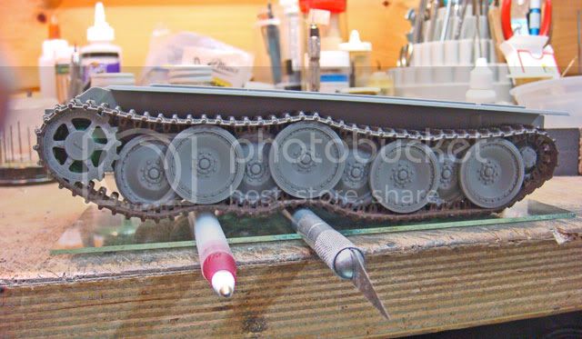
The Fruil tracks were a PITA to clean up, Frankly, I think that their molds are showing their age a bit. Every other lightening hole in the guide teeth was flashed over and each link had very promanent mold seams on the interior faces. Also, each of the drive sprocket tooth holes need some cleaning up. So, I spent hours cleaning the tracks up. However, they do look the part once finished. I darkened them up using "Blacken' It" in preparation for final weathering later.
The kit's idler wheels and drive sprockets also needed some fitting to get them to work with the Fruils. The outter faces of the idlers needed to be thinned down to fit between the track guide horns. The inside faces of the kit's drive sprockets also need thinning down to fit over the guide horns and into the holes.
I also test fitted the track length and once adjusted, I glued the idler wheel axels in place.
I pre-painted the interior of the hull flat black and detail painted the engine radiator / fan modules. Be careful of the orientation of these modules when you glue them into the lower hull. They can be installed 180 degrees incorrectly. When correct, they should generally follow the profile of the Panther's wedge-shaped hull when viewed from the side. If you install them backwards, their fronts will be too tall and interfer with the upper hull roof.
My upper hull was warped or bowed quite a bit and no amount of dry-fitting seemed to flatten out the hull roof, so I added two lateral "stiffeners," one in front of the turret ring and one behind it. I made these from thick rectangular styrene stock, but I think a couple of pieces of the kit sprue would work just as well, These stiffeners were tightly clamped into the interior of the upper hull, glued, and allowed to dry over night.
The upper hull requires some careful gluing to get a tight fit all around the lower hull. I first glued the rear hull in place and allowed that to dry over night. Then the upper hull was added and carefully clamped using rubber bands and cloths pins. It was then glued and allowed to dry over night.
Here's another check of the hull and suspension fit after the hull was glued up:
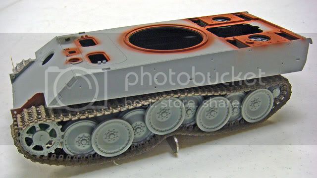
This time with both sets of wheels and tracks.
More to follow...
Again, our build notes explain some of the DML suspension optional parts (like late and early bumber stops, the final drive with the return roller or track skid, etc.)
One thing that isn't included in our notes yet is the issue with the last two suspension arms on each side of the hull.
DML would have you use parts E2, E6, and E7 to make these four stations (the last two on each side). My suggestion is to use a combination of parts E2 and E5. These parts, E2 and 5, are identical and the last two swing arms on each side should be the same as the first swing arm (E2).
There is another option on the real tank where the last two swing arms are the same as the center four arms (kit parts E6 + A26). However, these last swing arms did not have the armored guard around the large hex nuts (kit parts A26). So, what you need are four parts E7 (looks like an E6 with a plain hex nut and no guard). Check your references, but the kit instructions are wrong either way.
As I mentioned earlier, I plan on displaying my tank's suspension articulated. DML makes this a piece of cake to do.
I glued the first and last swing arm on each side in place at the small "half-moon" pins molded on the swing arm and hull side. I weighed down the model and dry-fit road wheels to each of these arms and allowed them to dry over night.
I then cut off the same half-moon shaped pins on all of the remaining swing arms and the hull sides (these pins are not present on the real tank). I then glued the torsion bars to their anchor points on the opposite interior hull sides.
That's all that's necessary.
Here's a picture of my first articulation test fit (with the Fruil tracks and wheels dry-fit):
The Fruil tracks were a PITA to clean up, Frankly, I think that their molds are showing their age a bit. Every other lightening hole in the guide teeth was flashed over and each link had very promanent mold seams on the interior faces. Also, each of the drive sprocket tooth holes need some cleaning up. So, I spent hours cleaning the tracks up. However, they do look the part once finished. I darkened them up using "Blacken' It" in preparation for final weathering later.
The kit's idler wheels and drive sprockets also needed some fitting to get them to work with the Fruils. The outter faces of the idlers needed to be thinned down to fit between the track guide horns. The inside faces of the kit's drive sprockets also need thinning down to fit over the guide horns and into the holes.
I also test fitted the track length and once adjusted, I glued the idler wheel axels in place.
I pre-painted the interior of the hull flat black and detail painted the engine radiator / fan modules. Be careful of the orientation of these modules when you glue them into the lower hull. They can be installed 180 degrees incorrectly. When correct, they should generally follow the profile of the Panther's wedge-shaped hull when viewed from the side. If you install them backwards, their fronts will be too tall and interfer with the upper hull roof.
My upper hull was warped or bowed quite a bit and no amount of dry-fitting seemed to flatten out the hull roof, so I added two lateral "stiffeners," one in front of the turret ring and one behind it. I made these from thick rectangular styrene stock, but I think a couple of pieces of the kit sprue would work just as well, These stiffeners were tightly clamped into the interior of the upper hull, glued, and allowed to dry over night.
The upper hull requires some careful gluing to get a tight fit all around the lower hull. I first glued the rear hull in place and allowed that to dry over night. Then the upper hull was added and carefully clamped using rubber bands and cloths pins. It was then glued and allowed to dry over night.
Here's another check of the hull and suspension fit after the hull was glued up:
This time with both sets of wheels and tracks.
More to follow...
SdAufKla
Joined: May 07, 2010
KitMaker: 2,238 posts
Armorama: 2,158 posts
Posted: Tuesday, September 27, 2011 - 10:31 AM UTC
Quoted Text
Impressive start, Mike!
Dan
Thanks Dan!
I really need to start posting these things when I actually start them and not wait until I have a pile'o pictures and trying to do it all at once!

panamadan
Joined: July 20, 2004
KitMaker: 1,513 posts
Armorama: 1,449 posts
Posted: Tuesday, September 27, 2011 - 10:55 AM UTC
You're doing fine!
Dan
Dan
SdAufKla
Joined: May 07, 2010
KitMaker: 2,238 posts
Armorama: 2,158 posts
Posted: Tuesday, September 27, 2011 - 10:57 AM UTC
With the hull guled up, I started working on the engine deck and rear hull details, but first I did tighten-up some seems, weld marks and the locating pin holes on the hull.
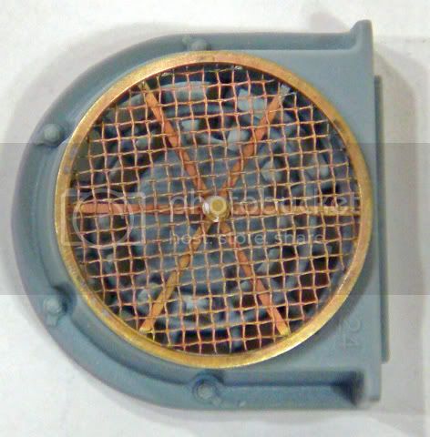
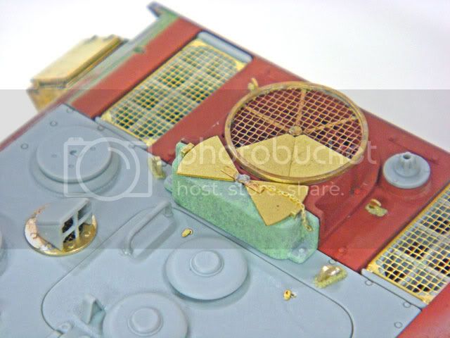
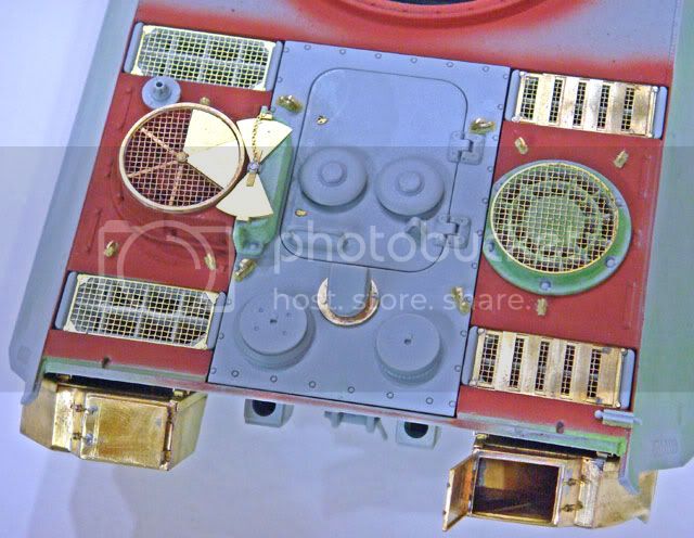
The first of the engine deck details was the crew compartment heater and air deflectors. The AM-Works PE parts are a great improvement over the kit parts (which are really not too bad).
The screen and air deflector mount is a stack of PE parts that were soldered around their circumference and cleaned up. The center air deflector hold-down bolt and washer are not indicated on the PE instructions but are included in the set (PE part C11). (Brain says that the PE instructions will be amended.)
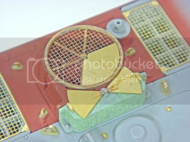
I soldered a wire pin on the bottom of my C11 washer-nut so that I can add the pie-shaped air deflectors later as I'm painting the tank. I also deviated from the PE instrucitons with the air deflector stowage clamps. I didn't use the center PE part A5 and left a little bit of the plastic on kit part D12 as gluing points for the PE parts C1 (on the instructions but un-numbered on the fret). I also used a piece of spare keeper chain left over from the cleaning rod tube assembly to make a keeper chain for PE part A6.
I still have to add hex bolts to the vertical flanges between kit parts C21 and D12. I did enhance their "cast" texture with some thinned Squadron Green Putty.
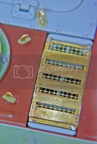
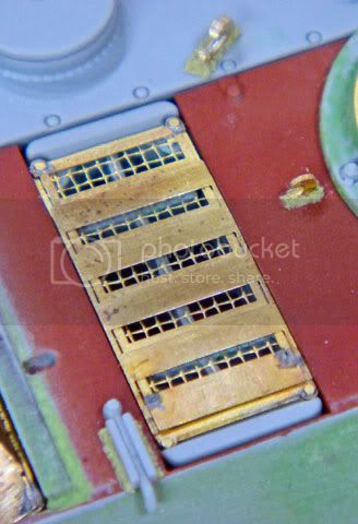
The winter louvers on the right / starboard side of the engine deck were made from the PE parts. These took some thought to determine the best way to assemble them.
I started by soldering the two louver parts, PE C3 and C3, together. I then soldered the two wing nuts, PE C5, to the single louver. This sub-assembly was then soldered to the other louvers. I then soldered the screen, PE C1 to the louver assemblies. This was just done on the corners. Finally, I soldered the smaller hex nuts, E7, to each corner using low-temp solder. Using this sequence, I was able to keep the allignment of the louvers and screens looking "mechanically precise."
The engine deck lifing hooks all need to have their locating holes filled since the PE hooks are designed to sit flush with the deck surface. In all honesty, the plastic kit hooks look pretty good, but I enjoyed the challenge of adding the PE hooks and I was going to add the weld beads anyways.
I also added the little dust / dirt covers over the engine hatch latches. These are included in the PE set but not called out in the instructions. I scraped off the molded-on latch covers, drilled counter-sinks and installed mocro-sized PE washers to simulate the latch holes. I then added the PE latch covers.
The opening for the snorkle tube on the engine deck is also made with a stack of PE parts that include a nice open screen. These were very easy to solder together and make for another good "confidence target" to try out your soldering skills. Clamp the entire stack together and solder around the edges.
More to follow...
The first of the engine deck details was the crew compartment heater and air deflectors. The AM-Works PE parts are a great improvement over the kit parts (which are really not too bad).
The screen and air deflector mount is a stack of PE parts that were soldered around their circumference and cleaned up. The center air deflector hold-down bolt and washer are not indicated on the PE instructions but are included in the set (PE part C11). (Brain says that the PE instructions will be amended.)
I soldered a wire pin on the bottom of my C11 washer-nut so that I can add the pie-shaped air deflectors later as I'm painting the tank. I also deviated from the PE instrucitons with the air deflector stowage clamps. I didn't use the center PE part A5 and left a little bit of the plastic on kit part D12 as gluing points for the PE parts C1 (on the instructions but un-numbered on the fret). I also used a piece of spare keeper chain left over from the cleaning rod tube assembly to make a keeper chain for PE part A6.
I still have to add hex bolts to the vertical flanges between kit parts C21 and D12. I did enhance their "cast" texture with some thinned Squadron Green Putty.
The winter louvers on the right / starboard side of the engine deck were made from the PE parts. These took some thought to determine the best way to assemble them.
I started by soldering the two louver parts, PE C3 and C3, together. I then soldered the two wing nuts, PE C5, to the single louver. This sub-assembly was then soldered to the other louvers. I then soldered the screen, PE C1 to the louver assemblies. This was just done on the corners. Finally, I soldered the smaller hex nuts, E7, to each corner using low-temp solder. Using this sequence, I was able to keep the allignment of the louvers and screens looking "mechanically precise."
The engine deck lifing hooks all need to have their locating holes filled since the PE hooks are designed to sit flush with the deck surface. In all honesty, the plastic kit hooks look pretty good, but I enjoyed the challenge of adding the PE hooks and I was going to add the weld beads anyways.
I also added the little dust / dirt covers over the engine hatch latches. These are included in the PE set but not called out in the instructions. I scraped off the molded-on latch covers, drilled counter-sinks and installed mocro-sized PE washers to simulate the latch holes. I then added the PE latch covers.
The opening for the snorkle tube on the engine deck is also made with a stack of PE parts that include a nice open screen. These were very easy to solder together and make for another good "confidence target" to try out your soldering skills. Clamp the entire stack together and solder around the edges.
More to follow...
SdAufKla
Joined: May 07, 2010
KitMaker: 2,238 posts
Armorama: 2,158 posts
Posted: Tuesday, September 27, 2011 - 11:09 AM UTC
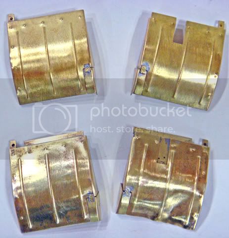
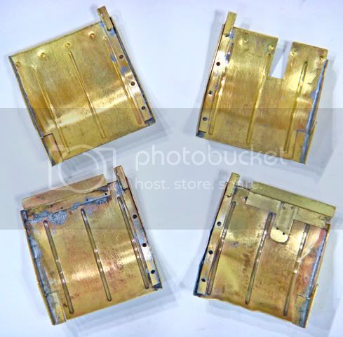
Moving on to the rear hull, I've now added the PE mounting loops and bottom plates for the stowage boxes.
Here is where having the PE sub-assemblies ready pays off. You can't add the mounting hardward to the hull until you have the boxes built so that you can use them to measure and mark the attachment points for the hardware.
I did find that the PE bottom plates on my model fit better without any bending. The prototypes have a slight up-sweep bend from the rear edge of the pannier to the bottoms of the stowage boxes. However, my boxes fit perfectly flat on the bottom plates.
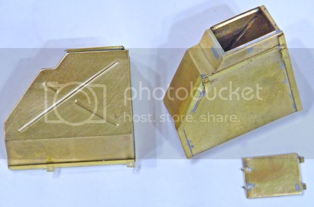
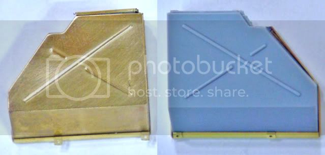
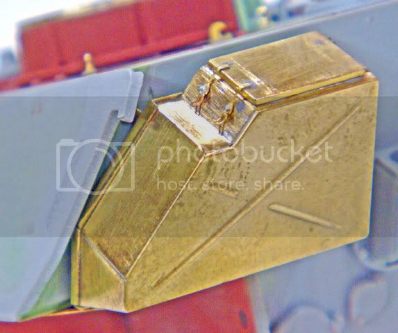
Here again, I sumulated damage on one of the stowage boxes and left its lid "sprung" open. And again, here is where soldering pays off with that durability thing. I crushed my box by laying a wooden paint brush handle on it and hitting it with a hammer (I was thinking of how it would look if the driver backed the tank into a tree). Only a solder joint would take this kind of pounding.
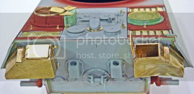
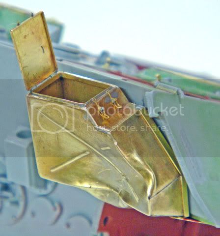
The boxes are simply dry-fit in these photos. This is so that I can remove them and get the primer red paint under them and on the hull rear. Also, this gives me some working room when I add the other rear hull details.
More to follow....
Here is where having the PE sub-assemblies ready pays off. You can't add the mounting hardward to the hull until you have the boxes built so that you can use them to measure and mark the attachment points for the hardware.
I did find that the PE bottom plates on my model fit better without any bending. The prototypes have a slight up-sweep bend from the rear edge of the pannier to the bottoms of the stowage boxes. However, my boxes fit perfectly flat on the bottom plates.
Here again, I sumulated damage on one of the stowage boxes and left its lid "sprung" open. And again, here is where soldering pays off with that durability thing. I crushed my box by laying a wooden paint brush handle on it and hitting it with a hammer (I was thinking of how it would look if the driver backed the tank into a tree). Only a solder joint would take this kind of pounding.
The boxes are simply dry-fit in these photos. This is so that I can remove them and get the primer red paint under them and on the hull rear. Also, this gives me some working room when I add the other rear hull details.
More to follow....
SdAufKla
Joined: May 07, 2010
KitMaker: 2,238 posts
Armorama: 2,158 posts
Posted: Tuesday, September 27, 2011 - 11:17 AM UTC
Well, I think this is the final post on this thread for today...
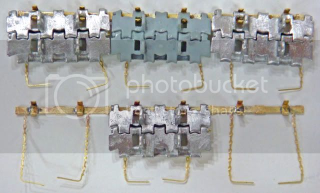
Here're the spare track hangers. These are obviously PE parts. The AM-Works hangers worked equally well with both the kit Magic Tarck and the Fruils.
These are another great set of PE assemblies to try out soldering on. The hook parts are very easy to clamp to the mounting bar and solder individually. Each one is far enough from its neighbors that no heat sinks were required. I simply worked my way from one end to the other.
Note that the pins and keeper chains are already etched to the mounting bar, so these don't need to be added separately.
So, that's all for now. Next up will be the remainder of the rear hull details followed by the Schurtzen and side "fenders."
'Til then, happy modeling!
SdAufKla
Joined: May 07, 2010
KitMaker: 2,238 posts
Armorama: 2,158 posts
Posted: Tuesday, September 27, 2011 - 11:24 AM UTC
Quoted Text
I actually just bought 6268, Dragon's Panther G with the rear steel wheels, AM Works Panther stuff and an Aber Barrel. I'll start it as soon as I get it and will be subscribing to this as well.
Very cool, Sean! Several of our members are using that kit for their build-ups.
If I'm not mistaken, it also incudes the rubber tired wheels need to build the standard production vehicle.
I was very tempted myself to use that kit and do it in the two-color cammo scheme. I was thinking about the tank in the Patton museum collection that was captured in brown and green...
Hope you find some info here and on our website useful!
SdAufKla
Joined: May 07, 2010
KitMaker: 2,238 posts
Armorama: 2,158 posts
Posted: Wednesday, September 28, 2011 - 02:28 AM UTC
Thanks for the tips, Brian!
The chains and pins etched onto the mounting bar was a pretty elegant solution to the design of the assembly and one that saves a lot of work over adding those details separately.
For sure the parts do need some careful handling to remove them from the fret, but it's really not too bad. However, these track hangers were very easy to solder up since you don't have to work around two very close joints (a hook and a chain).
All that I needed to clamp each successive hook was a pair of tweezers. Once that hook had been soldered, I then just moved to the next. Very fast and easy clamping that was tight and which made for neat and clean joints.
I'll be sure to check my references for those chain attachment locations before final assembly.

metooshelah

#011

Joined: February 06, 2009
KitMaker: 1,507 posts
Armorama: 1,304 posts

Posted: Wednesday, September 28, 2011 - 02:50 AM UTC
wow, your build is really impressive. keep it up!
SdAufKla
Joined: May 07, 2010
KitMaker: 2,238 posts
Armorama: 2,158 posts
Posted: Saturday, October 01, 2011 - 08:13 AM UTC
@ Matan: Thanks for the props!
Well, after so much of this thread went off on a tangent discussing techniques and methods:
News Dealing with PE A new DVD
I thought I'd add a few more detailed "how-to" photos in this next up-date. I've been working on the side fenders lately, and they each have 6 SChurtzen hangers that have to be folded and then soldered onto the fenders proper.
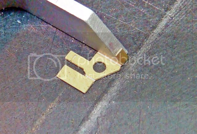
One of the questions on the PE DVD thread was how to get the most out of one of the Small Shop "Hold 'n Fold" bending tools. There are no hard and fast rules for the sequence of folds or bends, but here is an example of how one of these can be used fairly efficiently.
I started off by removing all of the Schurtzen hangers from the PE fret and cleaning them up. To clean them, I held them with a pair of tweezers and used a small sanding block and a Flexi-File to remove the attachment burrs.
Here you can see one of the hangers and several that have already been folded. To fold these, I placed the flat part in the Hold 'n Fold under one "finger" with two of the fold lines at 90 degrees to each other:
I then made two consecutive folds without having to move the part:
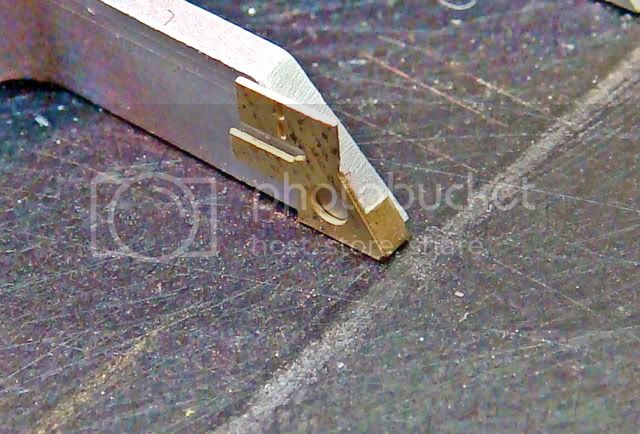
I then un-clamped the part, rotated it 180 degrees and repositioned it again where I could make two consecutive folds:
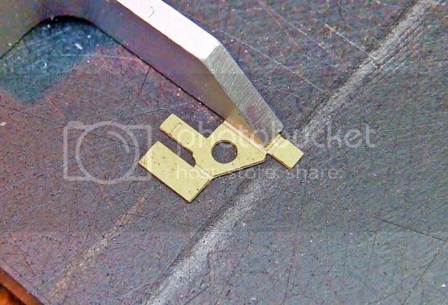
Here I could have un-clamped the part and postioned it under the Hold 'n Fold for the last fold. However, lining up the fold lines is sometimes kind of slow. A faster way to make this last, single small fold is by going "old school" and using hand tools. So....
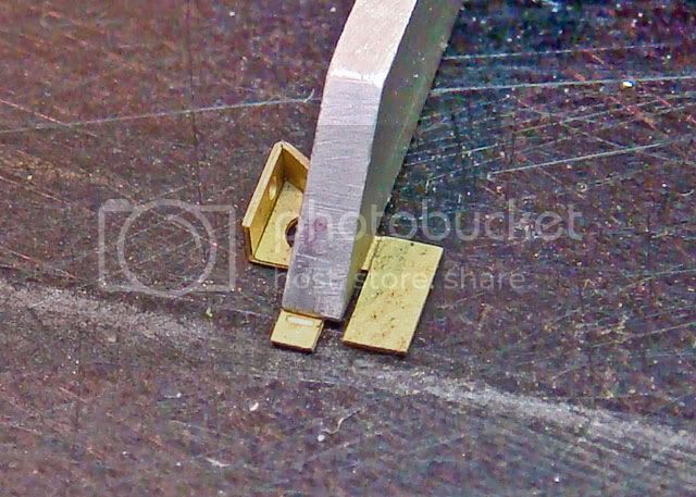
With these two folds, I was done with the Hold 'n Fold. I unclamped the part and then positioned the last bending line in a pair of flat-tip pliers:
I then made the last fold using the edge of a razor blade:
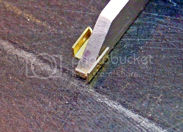
And here's the finished, folded Schurtzen hanger:
So, this was all pretty fast and took much less time to do than to type up here. The point is to try to use the bending tool as efficeiently as possible. It's often possible to make multiple folds like this without having to reposition the PE part. Here, I was able to make 4 folds with only 1 change of position.
This same method works on small open boxes, too. Position the part to fold two sides consecutively using the corner of one of the fingers. Loosen the clamp, slide the part over to the opposite side fold line, tighten, and make the third fold. Loosen up again, slide the part partially out to the last fold line, tighten and make the fourth fold by clamoing the last side and folding the entire box upward.
HTH,
Well, after so much of this thread went off on a tangent discussing techniques and methods:
News Dealing with PE A new DVD
I thought I'd add a few more detailed "how-to" photos in this next up-date. I've been working on the side fenders lately, and they each have 6 SChurtzen hangers that have to be folded and then soldered onto the fenders proper.
One of the questions on the PE DVD thread was how to get the most out of one of the Small Shop "Hold 'n Fold" bending tools. There are no hard and fast rules for the sequence of folds or bends, but here is an example of how one of these can be used fairly efficiently.
I started off by removing all of the Schurtzen hangers from the PE fret and cleaning them up. To clean them, I held them with a pair of tweezers and used a small sanding block and a Flexi-File to remove the attachment burrs.
Here you can see one of the hangers and several that have already been folded. To fold these, I placed the flat part in the Hold 'n Fold under one "finger" with two of the fold lines at 90 degrees to each other:
I then made two consecutive folds without having to move the part:
I then un-clamped the part, rotated it 180 degrees and repositioned it again where I could make two consecutive folds:
Here I could have un-clamped the part and postioned it under the Hold 'n Fold for the last fold. However, lining up the fold lines is sometimes kind of slow. A faster way to make this last, single small fold is by going "old school" and using hand tools. So....
With these two folds, I was done with the Hold 'n Fold. I unclamped the part and then positioned the last bending line in a pair of flat-tip pliers:
I then made the last fold using the edge of a razor blade:
And here's the finished, folded Schurtzen hanger:
So, this was all pretty fast and took much less time to do than to type up here. The point is to try to use the bending tool as efficeiently as possible. It's often possible to make multiple folds like this without having to reposition the PE part. Here, I was able to make 4 folds with only 1 change of position.
This same method works on small open boxes, too. Position the part to fold two sides consecutively using the corner of one of the fingers. Loosen the clamp, slide the part over to the opposite side fold line, tighten, and make the third fold. Loosen up again, slide the part partially out to the last fold line, tighten and make the fourth fold by clamoing the last side and folding the entire box upward.
HTH,
panamadan
Joined: July 20, 2004
KitMaker: 1,513 posts
Armorama: 1,449 posts
Posted: Saturday, October 01, 2011 - 08:31 AM UTC
That's a good SBS!
Dan
Dan
SdAufKla
Joined: May 07, 2010
KitMaker: 2,238 posts
Armorama: 2,158 posts
Posted: Saturday, October 01, 2011 - 08:32 AM UTC
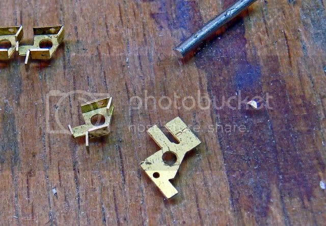
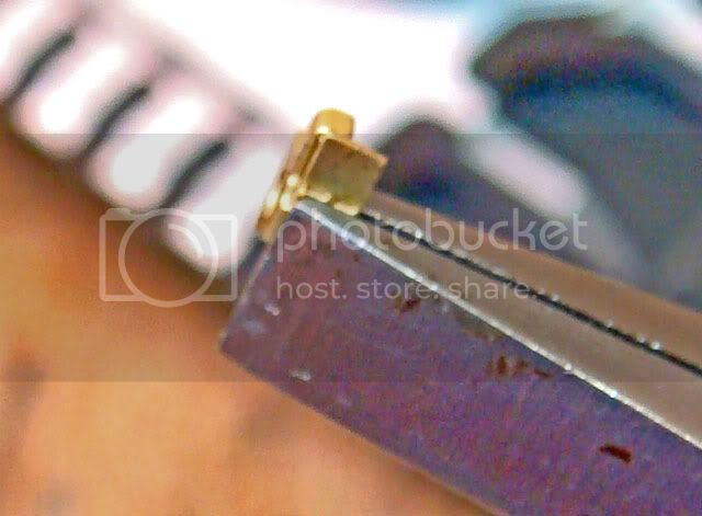
Another point that was made in the PE DVD thread was to use a very small amount of solder when building PE assemblies.
Here's what is meant by a "small amount" of solder:
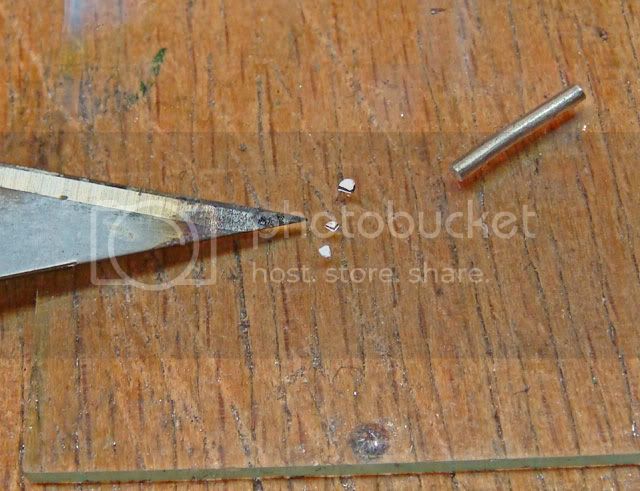
To the left is the tip of an X-acto #11 blade and the solder wire is about 1.5 mm in diameter. Here I've sliced a small disk from the end of the solder wire and then quartered the disk. Often times you need to slice these little bits even smaller.
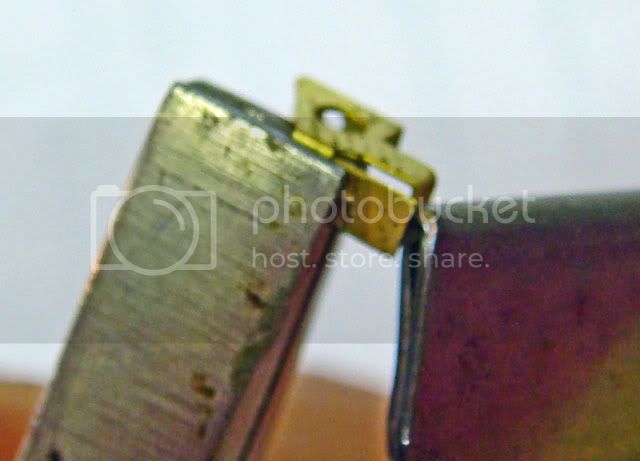
Here's one of the Schurtzen hangers positioned on the bottom of one of the side fenders. I'm clamping it to the fender with a pair of fine-tipped tweezers held in my other hand. I've added a small drop of liquid flux and dabbed up the excess with the corner of a paper towel. I've then added two of the small solder chips shown in the last photo:
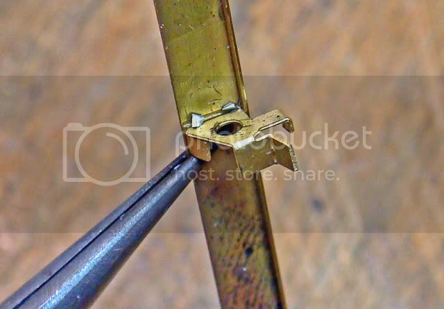
I then applied the heat to the hanger-fender joint using my micro-torch. (See the PE DVD thread for a longish discussion of the pros of using a butane torch over an electric soldering iron.) The application of heat took about 2-3 seconds before the solder melted and flowed.
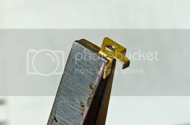
Here's the final result:
(Sorry for the poor focus - I can use my torch one-handed but appearently I can't take a picture that way! )
)
I then just moved to the next hanger and repeated the process working my way from one end of the side fender to the other. Each successive joint was made "away" from my body with the previous joint next to the handles of the tweezers. This way I was able to apply the heat in a direction away from my body and the last joint and so I didn't need any heat sinks or other tricks.
BTW: This is the same way I did the spare track hangers. No heat sinks and only a pair of tweezers needed for clamping.
Here's what is meant by a "small amount" of solder:
To the left is the tip of an X-acto #11 blade and the solder wire is about 1.5 mm in diameter. Here I've sliced a small disk from the end of the solder wire and then quartered the disk. Often times you need to slice these little bits even smaller.
Here's one of the Schurtzen hangers positioned on the bottom of one of the side fenders. I'm clamping it to the fender with a pair of fine-tipped tweezers held in my other hand. I've added a small drop of liquid flux and dabbed up the excess with the corner of a paper towel. I've then added two of the small solder chips shown in the last photo:
I then applied the heat to the hanger-fender joint using my micro-torch. (See the PE DVD thread for a longish discussion of the pros of using a butane torch over an electric soldering iron.) The application of heat took about 2-3 seconds before the solder melted and flowed.
Here's the final result:
(Sorry for the poor focus - I can use my torch one-handed but appearently I can't take a picture that way!
)I then just moved to the next hanger and repeated the process working my way from one end of the side fender to the other. Each successive joint was made "away" from my body with the previous joint next to the handles of the tweezers. This way I was able to apply the heat in a direction away from my body and the last joint and so I didn't need any heat sinks or other tricks.
BTW: This is the same way I did the spare track hangers. No heat sinks and only a pair of tweezers needed for clamping.
SdAufKla
Joined: May 07, 2010
KitMaker: 2,238 posts
Armorama: 2,158 posts
Posted: Saturday, October 01, 2011 - 08:48 AM UTC
@ Dan: Cheers! Hope someone finds it useful.
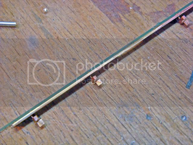
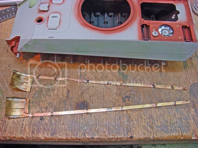
So, with the hangers on each of the side fenders, I went over them and took some time straighten them out using a piece of glass to line them against:
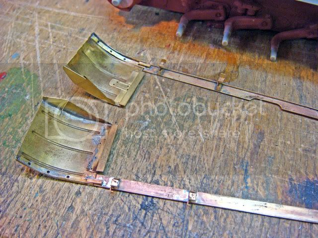
On the prototype, the edges of the side and front fenders match each other, so in order to ensure that all of my fender parts line up on the model's side, I soldered the front fender assemblies to the side fenders:
Clamping these was done exactly as described above, and this time I used a low-temp solder to join the two.
(Again, see the PE DVD thread for a discussion of the differences between high- and low-temp solders and some links for sources.)
Next, I dry-fit the fender assemblies to the model using a pencil line drawn on the vehicle's side. This line follows the original alignment holes molded on the model. Here I've filled these with CA and brushed thinned Squadron Green Stuff over them to ensire they're completely filled. The CA and putty were sanded smooth.
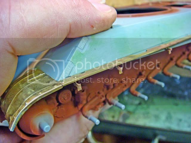
Dry-fit, dry-fit, dry-fit! When replacing major kit parts and sub-assemblies with AM parts (either resin, PE, white metal, or all three), you need to test fit, adjust, test fit and adjust more to get everything looking and fitting as nice as the original kit.
For example, you'll note that the left side fenders have a cut-out for the shovel head. So, before gluing on the tool rack, we need the fenders completed and glued on to make sure the shovel will be positioned correctly, and so on and so on...
Well, with these, I've finished all of the PE assemblies for the hull and chassis, so in my next posts, I hope to show some real progress!
Later mates!
So, with the hangers on each of the side fenders, I went over them and took some time straighten them out using a piece of glass to line them against:
On the prototype, the edges of the side and front fenders match each other, so in order to ensure that all of my fender parts line up on the model's side, I soldered the front fender assemblies to the side fenders:
Clamping these was done exactly as described above, and this time I used a low-temp solder to join the two.
(Again, see the PE DVD thread for a discussion of the differences between high- and low-temp solders and some links for sources.)
Next, I dry-fit the fender assemblies to the model using a pencil line drawn on the vehicle's side. This line follows the original alignment holes molded on the model. Here I've filled these with CA and brushed thinned Squadron Green Stuff over them to ensire they're completely filled. The CA and putty were sanded smooth.
Dry-fit, dry-fit, dry-fit! When replacing major kit parts and sub-assemblies with AM parts (either resin, PE, white metal, or all three), you need to test fit, adjust, test fit and adjust more to get everything looking and fitting as nice as the original kit.
For example, you'll note that the left side fenders have a cut-out for the shovel head. So, before gluing on the tool rack, we need the fenders completed and glued on to make sure the shovel will be positioned correctly, and so on and so on...
Well, with these, I've finished all of the PE assemblies for the hull and chassis, so in my next posts, I hope to show some real progress!
Later mates!
pseudorealityx
Joined: January 31, 2010
KitMaker: 2,191 posts
Armorama: 1,814 posts
Posted: Saturday, October 01, 2011 - 01:21 PM UTC
Looking good Mike. You planning on bringing these (hopefully completed) to the ATL show in Feb?
SdAufKla
Joined: May 07, 2010
KitMaker: 2,238 posts
Armorama: 2,158 posts
Posted: Sunday, October 02, 2011 - 01:46 AM UTC
Quoted Text
Looking good Mike. You planning on bringing these (hopefully completed) to the ATL show in Feb?
Hi Jesse,
Thanks for the kind words...
Oh yea! We had a great time at the show last year, so I'm really looking forward to the Atlanta AMPS Regional again in Feb!
I'm planning on finishing this one and my StuG IV vignette by then and will bring both.
AMPS Atlanta 2012 Show
Hope to see ya there!

Lucky13

Joined: June 01, 2006
KitMaker: 1,707 posts
Armorama: 46 posts

Posted: Sunday, October 02, 2011 - 02:05 AM UTC
Fantastic work!!
 |

WEB HOSTING BY


Copyright ©2021 Armorama and Kitmaker Network, a subsidiary of Silver Star Enterprises
All Rights Reserved. Please read our Conditions of Use and Privacy Policy.
All Rights Reserved. Please read our Conditions of Use and Privacy Policy.