_GOTOBOTTOM
Dioramas: Making Bases
Discuss all aspects of making bases.
Hosted by Darren Baker
Diorama in 1/16 - building the 1st module
lappes
Visit this Community
Baden-Württemberg, Germany
Joined: July 29, 2012
KitMaker: 133 posts
Armorama: 133 posts
Posted: Sunday, August 05, 2012 - 04:20 AM UTC
Report of the building of my Diorama in 1/16.

The Diorama is made of 2 modules - the first one contains a T34 85 wreck and measures 60 x 60 centimeters.

At first some pictures of the finished module.


Building report of the 1st Module of the diorama "suspicious noises in front of the T34"


Scale 1:16


The context of the Dios:

Hungary in the late summer of 1944. German soldiers have temporarily taken a destroyed factory. A Russian T 34 85 is burned in a bombed-out factory workshop.A German soldier noticed on the opposite side of the hall a suspicious movement and immediately stop in the MP40. An SS Untersturmführer looked over at him enquiring, his cigarette still in hand.

Kits of the 1st module:


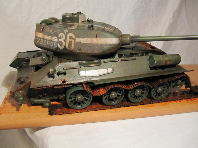
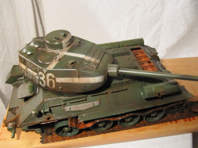
The T34 as I receive it. The modell is by Wasan, buyed privat in ebay.

Not yet completely built, the battery defect, mechanics?, battery box grotty installed .... but anyway .... because of this it should be a wreck on a diorama.


The T34:

The damage of the T34 was prepared.

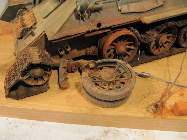
The idler wheel and the first on the left have been removed (simulation of a hit), the track was cut and removed the rubber tires of the wheels (fire damage). The arm of the 2nd track roller was unhooked from the spring strut to represent a fraction of the shock absorber.

The left fender was removed and the armored hull over the hit point was damaged.

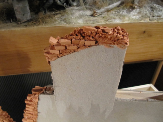
The T34 will stand on a heap of rubble.


The opening of the ventilating fan has been cutting-off with the Dremel.

A few details of the armored hull were added and the damaged area was sanded. The front-left suspension arm has got a flange for the blasted wheel. This will be completed by bolt holes or broken screws.

The rear independent arm on the right side were hung from the struts, otherwise the wheels will not touch the ground, because the vehicle is hanging due to the lack of wheels on the left side front.


Meanwhile, the external tanks are assembled and dented. For this they were heated over a candle and carefully with the back of a knife pressed the dents. It must be very careful in order not to let it look unrealistic.
The procedure was the same way with fenders.
The blades of ventilation opening below the cut-out protection grids were simulated with cardboard.


I then subjected the whole tank a fading, ie: with a toothpick, I distributed over the entire surface little color points with oil paint burnt umber,English Red bright, white and green earth. These were spread with a brush in the direction of flow, and then further processed by dilution.

The fan blades were painted burnt umber and english red light.


Finally, I have treated the tracks with highly diluted oil colours english red bright.

Further processing takes place after the drying of oil paint.

Now, the detailing of the T34 at the site of damage has been again revised.

The headlamp lens was destroyed,the disrupted cable to the headlamp and horn was made of florist wire.

The idler wheel has now been completed yet, but damaged. The chain was again separated and placed over the idler pulley.

The shot down wheel was treated . 5 holes were added to the flange of the wheel . Short pieces of florist wire were glued into the holes to simulate broken screws. Finally everything was again treated with oil paint english red light. The wet paint was sprinkled with pastel chalk orange and gently dabbed them lightly with a brush.


Now a further treatment was done with oil paints, pastels and pigments.

First, the armoured hull on the damaged side was painted with thinned oil paint English Red Light.Then came a careful washing with dilution.

Onto the wet paint I scraped chalk pastel orange with a knife.
With a stiff brush I dabbed and smeared wheels, radial arm and the side wall of the armoured hull) until the desired effect was achieved by me.

The rest of the armoured hull and the turret, I treated with Europe Dust pigment (Mig pigments)

Since the color of the oil washings wasn't dry, the pigments adhered pretty neat.

The chassis and the wheels I smeared with pigment fixer and dabbed with pigments Europe Dust.

Beware!! Never smear the pigments, because the pigment will immediately dissolve and become brown color without the desired dust effect!

At locations with a higher degree of pollution take enough pigments with the brush and dab at the wet spot.

Make sure the consistency is not too wet!

After the damaged side was also treated with Dust Europe in order to create a correct transition between the intact and the damaged side.

Finally, the chain was also treated.

Dust to Europe was in the structures of the chain rubbing.

This works very well, since the oil paint is not quite dry.


At locations with higher degree of pollution apply enough pigments with the brush and dab at the wet spot.


If everything is completely dry, the whole thing is sealed with matte clear coat carefully.

This is followed by further processing.

I've done a few things.

The damaged wheel was treated - englishrot, pastel orange, and even more Europe Dust.

The replacement tracks were attached to the bow and treated. The tow ropes are still treated and fixed.

So once again:


The burn marks were needed.

First, the T34 in places on the "burnt" side brushed with water and then sprinkled salt on it.

Once this had dried, I sprayed with the airbrush a bit of white about it.

After a short time I solved with a not too wet bristle brush by lightly brush over the salt.

It was a mottled appearance, which looks very realistic.

The images of the creation:


Now the whole thing on the same principle has been colored in black to simulate grime.

The first picture with salt, then processed the images, ie: salt is removed and treated with black pastel.


This was the building of the wreck.
I'll continue the report within a short time.

I beg your pardon for my bad english.
I hope, I haven't disgraced myself.

Best regards
Frank
roudeleiw
Visit this Community
Luxembourg
Joined: January 19, 2004
KitMaker: 2,406 posts
Armorama: 2,224 posts
Posted: Sunday, August 05, 2012 - 04:26 AM UTC
Great pictures! Thanks for showing them. Your english is fine

Claude

(mach langsam mit deinen Updates, es sind Ferien und du riskierst wenig Rückmeldung. Heb dir was auf für später. Nur so ein Tipp)
lappes
Visit this Community
Baden-Württemberg, Germany
Joined: July 29, 2012
KitMaker: 133 posts
Armorama: 133 posts
Posted: Sunday, August 05, 2012 - 04:29 AM UTC
Vielen Dank und guter Tipp
lappes
Visit this Community
Baden-Württemberg, Germany
Joined: July 29, 2012
KitMaker: 133 posts
Armorama: 133 posts
Posted: Sunday, August 05, 2012 - 07:41 AM UTC
The diorama -

Stage 1: the basic structure:

The first module has dimensions of 60 x 60cm. The second Module 60 cm wide and 70 cm long. The 2 modules are connected with 2 carriage bolts, 23 mm square bars of 80 cm length and 2 snap connectors.

The construction:

First, I created two identical frames of 23 mm square bar with outer dimensions of 58 x 58 cm.

At both frameworks, plywood planks were fixed by screwing from the backside of the frame. The screws must be short enough that they do not look out on the front. In addition the plywood was glued.

The distance of the both frames is also 23 mm to accommodate 23 mm square bars of 80 cm length for connection of the modules.

This enables a buckling resistant connection between the both modules.

When the plywood planks were fixed and the glue was dry, the groundplate was fixed.
The plate measured 58 x 58 cm and fitted exactly to the frame and forms the base for the construction of the terrain.

The base of the 2nd module of the diorama was made in the same way. The measures are 70 x 60 cm.


This part of the report was very technical and I hope I've made ​​myself comprehensible
lappes
Visit this Community
Baden-Württemberg, Germany
Joined: July 29, 2012
KitMaker: 133 posts
Armorama: 133 posts
Posted: Sunday, August 05, 2012 - 07:51 AM UTC
Here are just put together both modules.


lappes
Visit this Community
Baden-Württemberg, Germany
Joined: July 29, 2012
KitMaker: 133 posts
Armorama: 133 posts
Posted: Sunday, August 05, 2012 - 07:59 AM UTC


The diorama Part 2

The wall of the house:

A bar for attaching the wall was glued.

The bar consists of a balsa wood square edges with a width of 14mm each.

The bars were broken for the door opening. The 3rd Square wood was used as a ruler.

Then the modules were separated for the purpose of further processing easier to handle.

The border was sawn according to the different height levels of the site. The foam sheet was adapted. A stairway cut.

The T34 has been realigned.


lappes
Visit this Community
Baden-Württemberg, Germany
Joined: July 29, 2012
KitMaker: 133 posts
Armorama: 133 posts
Posted: Sunday, August 05, 2012 - 08:21 AM UTC
The next few days I built the wall of the ruined building.

I used chipboard to 2.1 mm in thickness.

First I drew in pencil on the outline and cut out the first page.

Then on the inside of a reinforcement bar made ​​of balsa square with edge length of 14mm. This was glued with UHU glue.

Balsa can be easily edited using the knife. To the lower edge of the board had to remain 14 mm distance, for even strips in order to fix the walls have been glued to the base plate.

Then the other side of the wall adapted to be affixed and after drying with a knife.

The panes were deliberately set very high, as it should be a factory building.

The walls have not yet been glued to the base plate, as indeed is still a surface treatment.


lappes
Visit this Community
Baden-Württemberg, Germany
Joined: July 29, 2012
KitMaker: 133 posts
Armorama: 133 posts
Posted: Sunday, August 05, 2012 - 08:31 AM UTC
After building the walls I was able to finish the stairs.

This was done with a sheet of plywood 12 x 16 cm as a side wall to which the stair treads were glued.

A small sheet of plywood has been placed on the top step as a platform.

The stairs were made of a wooden bar 14 mm high, 20 mm (1 mm overlap with the underlying level) deep and 110mm wide. This is equivalent to the reality:

Height 22.4 cm

Depth of 30 cm

Width of 176 cm

This seems quite realistic.

In addition, I built a small stairs behind the door.

The transition to the second Module has been further processed.

Here are the pictures.


lappes
Visit this Community
Baden-Württemberg, Germany
Joined: July 29, 2012
KitMaker: 133 posts
Armorama: 133 posts
Posted: Monday, August 06, 2012 - 08:54 AM UTC
Today I made ​​a little further with the walls. I've chosen for self-curing modeling clay.

I strongly recommend to cut only the required amount of clay and keep the unused in a discarded Tupperware container so that it does not dry out!!!


First I rolled a strip of modeling clay with a rolling pin to about 2 mm thickness. I fixed this with double sided tape on the wall and adapted this at the edges. Then I pressed a horizontal joints, the vertical joints came with a knife. In this way the brick wall was moulded.


Since I had now decided to make the broken edges with the self-hardening modeling clay, I made from a strip of clay a lot of bricks. In addition I was the first time modeling for about 15 minutes to dry and then cut them with a spatula to the right size.


Then I kneaded the mass of another piece of a "sausage" of about 2 cm thickness and pressed them onto the adhesive-coated edge of the wall.


The material was processed with a craft knife, that is:

I stuck the knife into the ground and turned it a little more back and forth. This gives a brashly appearance.


This is what I always made in small sections (about 2 to 3 cm)

Then with a knife a little hole was poked a little bigger, glue on a brick and it has been inserted into the hole and filled the surrounding clay with a rough texture..

The result looks like this:


Then I made about 2 to 3 million bricks from Keramiplast . For this I cut the rest of the pack the clay into approximately 4 mm thick slices. These sliceswere cut into strips and I parted in brick length.

Overnight, I let it dry and harden.

These bricks I need for further breakdown of the edges and for the rubble.

An illustration of the packed clay I add also.


After the "bricks" are cured, I modeled the broken edges of the 2nd Wall.

Treated similarly as in the first.

The clay was treated with the knife first, but over the whole area, ie: I poked the knife at first everything and not just 2 - 3 cm friable. Thus the mass of dried quickly and superficially they seemed even more crumbly. The handling with the bricks and the clay was fun and I think it may have to look at it. It is also relatively cheap compared to purchased bricks.

The pack (1000g) which cost € 5.99 in the craft store and is very productive.

Here are the results so far:


The report will be continued soon.

Regards
Frank
lappes
Visit this Community
Baden-Württemberg, Germany
Joined: July 29, 2012
KitMaker: 133 posts
Armorama: 133 posts
Posted: Friday, August 10, 2012 - 05:35 AM UTC
Now to the brick walls.
First I glued two-sided tape on the wall, then rolled a band modelling clay with the rolling pin. Straightens the edges with a knife and carefully dissolved the mass with a spatula from the surface.

The "pancake" was carefully adapted to the existing tile layer and then pressed, that the mass is held by the tape. Then adjusted the edges with a knife. With a metal ruler I pressed again the horizontal joints - at a constant distance and pay attention to correct horizontal alignment.

Then I pressed up the vertical joints with a nail arrows (tool is no matter, have taken the nail arrows only because the correct joint width). Edit always a little joint, in order to develop an irregular floor base.

When the area of joint was fitted, here and because different tiles have edited I, i.e.: crisp on the surface and this withdrawn to simulate damage (hard to describe, was feeling).

Finally it was adapting to the broken edge. A small lump was modelling clay knocked flat and cut into strips. The strips were cut into small pieces. One of the pieces modelling clay was then put on the spot and varnished with a knife with the adjacent tile of the wall. Then, the joint was drawn to. Appropriately, the length has been shortened and then the rest adapted with a knife to the broken edge.

I hope I've expressed myself not too cumbersome.

Here the images:


lappes
Visit this Community
Baden-Württemberg, Germany
Joined: July 29, 2012
KitMaker: 133 posts
Armorama: 133 posts
Posted: Friday, August 10, 2012 - 05:44 AM UTC
Now, the wall was completed.
The editing was as before.
The break lines could be better adapted than I had feared.


Now, I have provided the 2nd wall with brick. The transitions to the broken edge are still being adjusted. Then the processing is done on the back.

More edits will still follow because the wall is yet long not ready.

Here the previous state:


lappes
Visit this Community
Baden-Württemberg, Germany
Joined: July 29, 2012
KitMaker: 133 posts
Armorama: 133 posts
Posted: Friday, August 10, 2012 - 06:49 AM UTC
After the wall on this side is pretty well advanced, I am slowly beginning with the "work equipment".

First of all I soldered brass L-profiles to 6 frame carriers.
Then I put a metal broomstick with the Dremel and a cutoff wheel to the correct length.
This recreates a pipeline.
I have placed these components on the Dio for a test.
The tube is damaged still on the crack of the wall.
A walk for the maintenance of the pipeline is fixed on the frame base.
Other tubes and pipes are still complemented.

Here the images of test.


Meanwhile, I have soldered a metal section of the wooden planks .... I will never electronics technician - what a botch.


For a Test, I have fixed the wooden planks.

To get an idea of the size, I put the figures into the hallway.


lappes
Visit this Community
Baden-Württemberg, Germany
Joined: July 29, 2012
KitMaker: 133 posts
Armorama: 133 posts
Posted: Sunday, August 12, 2012 - 10:28 PM UTC
Now, I have started with the destruction of the walkway.

To do this I cutted the U-profiles of the walkway with the Dremel and a cut-off wheel.

Then I bent profiles with the caliper....really unruly, the parts.

The large tube I cutted with the Dremel and formed it by bending with a caliper. Also, I dented the tube with several blows with the caliper (for each work the right tool).

To turn the pipe down I dented it and then shaped it as desired.

The next step is the making of the railing.

Here the photos of the intermediate result.


lappes
Visit this Community
Baden-Württemberg, Germany
Joined: July 29, 2012
KitMaker: 133 posts
Armorama: 133 posts
Posted: Monday, August 13, 2012 - 11:44 PM UTC
The plastic pipes were not separated yet, because they give support to the provisional build-on framework.
Now I build the railing.
To do this, I use 2.4 mm and 1.8 mm galvanised wire, which I've bought in the do-it-yourself store.
First, I have drilled 4 holes at a distance in a line in a wooden plank and there plugged the posts of the railing.
Then I pinned the handrail with a clothes peg on a post and then I soldered the railing with the first post (I know why I have no profession that has to do with soldering already).
Then, the remaining solder points were used.
I soldered the handrail with the framework respectively walkway.
With the other site I proceeded as well, had to employ only 2 posts.
Both rails were still bent.
My god...hopefully I have solder nothing more....
By the way, still a square piece of balsa wood as a lintel was pasted to connect both walls.
This was covered with modelling clay.

Here the images:


roudeleiw
Visit this Community
Luxembourg
Joined: January 19, 2004
KitMaker: 2,406 posts
Armorama: 2,224 posts
Posted: Tuesday, August 14, 2012 - 12:36 AM UTC
Hi Frank

Man, you ahve enough pictures to fill a book ! :-)

Thanks for showing the process of your build. It is certainly appreciated from everyone all the while the response is not convincing for the moment (holiday time).
Wait a bit ( aweek or so) before you continue to update.
Let everybody the time to digest this first.

Claude

lappes
Visit this Community
Baden-Württemberg, Germany
Joined: July 29, 2012
KitMaker: 133 posts
Armorama: 133 posts
Posted: Tuesday, August 14, 2012 - 01:07 AM UTC
Thank you for the tip, Claude.
But there is so much to translate.....I presume it will last much more than one week.
lappes
Visit this Community
Baden-Württemberg, Germany
Joined: July 29, 2012
KitMaker: 133 posts
Armorama: 133 posts
Posted: Saturday, August 18, 2012 - 09:12 AM UTC
Now the other side of the wall was made. I used the same procedere as on the first side.

At first the wall of the staircase was made in the traditional way - first step two-sided tape was pasted at the wooden construction ,than modelling clay was rolled with a rolling pin and pasted on the two-sided tape - then joints engrave with the nail file - previously with the metal brackets the line of pressed, so that it not from the direction.
Then the stairs has been fixed on the wall with wood glue.
The broken edge of the staircase was made in the same way as the broken edge of the wall.
Here the current images... the walkway was photographed from another perspective.


Best regards
Frank
lappes
Visit this Community
Baden-Württemberg, Germany
Joined: July 29, 2012
KitMaker: 133 posts
Armorama: 133 posts
Posted: Sunday, August 19, 2012 - 07:56 AM UTC
Now I build the transvers wall. It was made of 14 mm wooden square rods.
Then I brazed the handrail for the stairs.


lappes
Visit this Community
Baden-Württemberg, Germany
Joined: July 29, 2012
KitMaker: 133 posts
Armorama: 133 posts
Posted: Sunday, August 19, 2012 - 08:23 AM UTC
The back of the transverse wall was created out of cardboard.

It will later filled.

Also have I the upper edge of the mount the stairs "bricked".

The stairs was shaped rough and uneven to simulate a concrete surface.


lappes
Visit this Community
Baden-Württemberg, Germany
Joined: July 29, 2012
KitMaker: 133 posts
Armorama: 133 posts
Posted: Sunday, August 19, 2012 - 09:03 AM UTC
Next, the other side of the wall made of cardboard was created.

Then I painted the stairs in grey.

The lintel of the door has been revised and the wall received a "concrete reinforcement" used outside and inside.
The window sills were bricked and the breaking point of the "concrete reinforcement" has been edited.
The window sills were constructed as follows:
First glue was applied, then a layer of modelling clay. These had I dry for a while and then poked with a knife into it to get a surface like cement. Then, bricks have been incorporated.
The breaking point of the "concrete reinforcement" has been edited in a similar way but without bricks. Instead, I was stuck in short wires to imitate shattered concrete. In this I speared small pieces of modelling clay to simulate shattered concrete pieces.


lappes
Visit this Community
Baden-Württemberg, Germany
Joined: July 29, 2012
KitMaker: 133 posts
Armorama: 133 posts
Posted: Tuesday, August 21, 2012 - 07:56 AM UTC
Then I built the brickwall outside the wall.
The same procedere as the other side of the wall.
I used double-sided tape and self-hardened modelling clay again.
This was structured with a nail file and a metall ruler.
To take the monotony, I've made the basement of "concrete". The modelling clay was applied slightly thicker.
Then I treated the surface with a bristle brush.
I swabbed the surface.
As a result, I received an irregular structure.


I have just edited the lintel and the breaking point.

Here again pictures:


Best regards
Frank
lappes
Visit this Community
Baden-Württemberg, Germany
Joined: July 29, 2012
KitMaker: 133 posts
Armorama: 133 posts
Posted: Tuesday, August 21, 2012 - 08:02 AM UTC
The walls were plastered now.
I've posted an example after which I myself have oriented.


lappes
Visit this Community
Baden-Württemberg, Germany
Joined: July 29, 2012
KitMaker: 133 posts
Armorama: 133 posts
Posted: Tuesday, August 21, 2012 - 08:42 AM UTC
Now I completed the last work with modeling clay to the brickwork.

The procedure I documented with pictures again.

- First, apply the glue


A bit modeling clay is pressed onto the adhesive area


With the file, press and tighten the joints. Press in the form of modeling clay.


Procedure at the doors:

- First, the adhesive is applied


Then a piece of modelling clay was adjusted in length and wide


This is pressed on the adhesive location and adapted


That looks after customizing and treating with the bristle brush like this


And so at the other door


lappes
Visit this Community
Baden-Württemberg, Germany
Joined: July 29, 2012
KitMaker: 133 posts
Armorama: 133 posts
Posted: Tuesday, August 21, 2012 - 08:56 AM UTC
The plaster has been corrected yet. By the way, plaster consists of Knauf Superkleber (Knauf super glue).
There can be used other materials but this was available.
The glue has proven itself as a plaster in my Dio "without food no fight or the pig from the recovery group" in german "Das Schwein vom Bergetrupp oder ohne Mampf kein Kampf".


Here some impressions of the current state


lappes
Visit this Community
Baden-Württemberg, Germany
Joined: July 29, 2012
KitMaker: 133 posts
Armorama: 133 posts
Posted: Tuesday, August 21, 2012 - 09:24 AM UTC
The painting on the wall of the house:

After the putty was dried , I could start with the paint.

First, the remains of the plaster were painted stone gray (Revell Aqua Color) .

It looked like this:


Then khaki brown (Revell Aqua Color) was dabbed on with a sponge.

The joints were partially painted white with a fine brush.


Now several bricks were painted white.

First color on a brick and then simultaneously with a bristle brush over rubbed to achieve a weathering effect.

Then a dry coat of plaster was done with white.

Now a few joints were painted with a mixture of rust and dark earth (Revell Aqua Color).


Some bricks were still painted.... brick red was too dark, so I used wood and African Brown (Revell aqua color)


The edges of the door way, I have dressed up with brass mounts.

The joints of the window sills were painted white -

Procedure as before: first painted with white and then traced with a bristle brush.


Unevenness in the joints were painted in white, it will look like excess cement.


And the overall view:


 _GOTOTOP