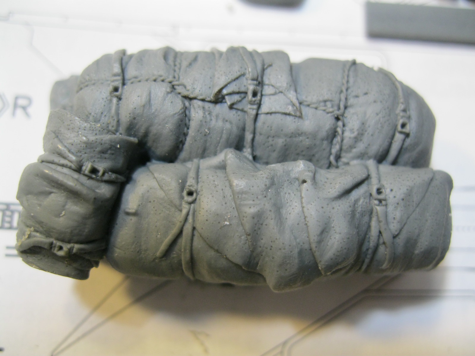
Thanks, Nick. It must have been raining when the photo of China Clipper was taken, based on all the mud. Makes me wonder how there is any soil left in France because you would think it was all carried away on tanks.
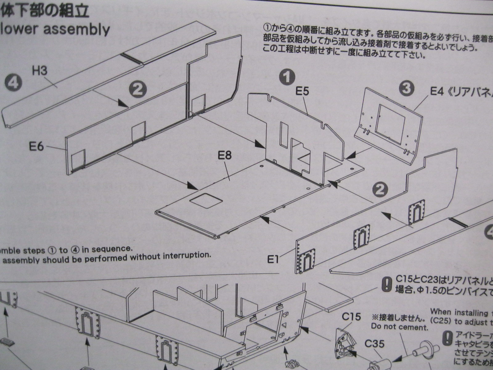
Bigger update today. Starting with the lower hull, I pulled out a small square to make sure everything was lined up properly. The hull parts fit well but are noticeably thinner than the typical molded hull tub. Makes for a better scale effect. It also makes me envious of the guys building all the new German tanks with full interiors. Nothing to show here.
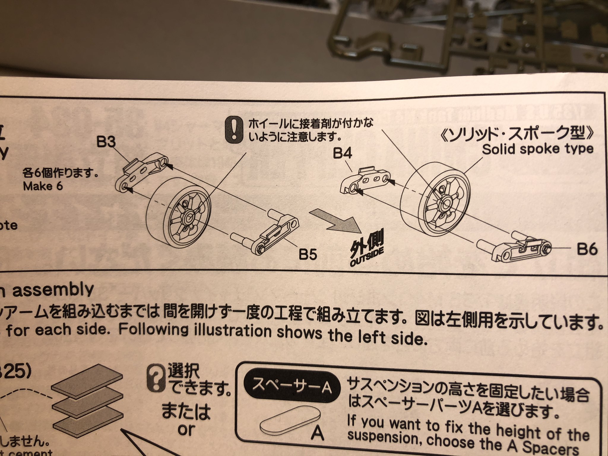
 IMG_9651
 by
russell amott, on Flickr
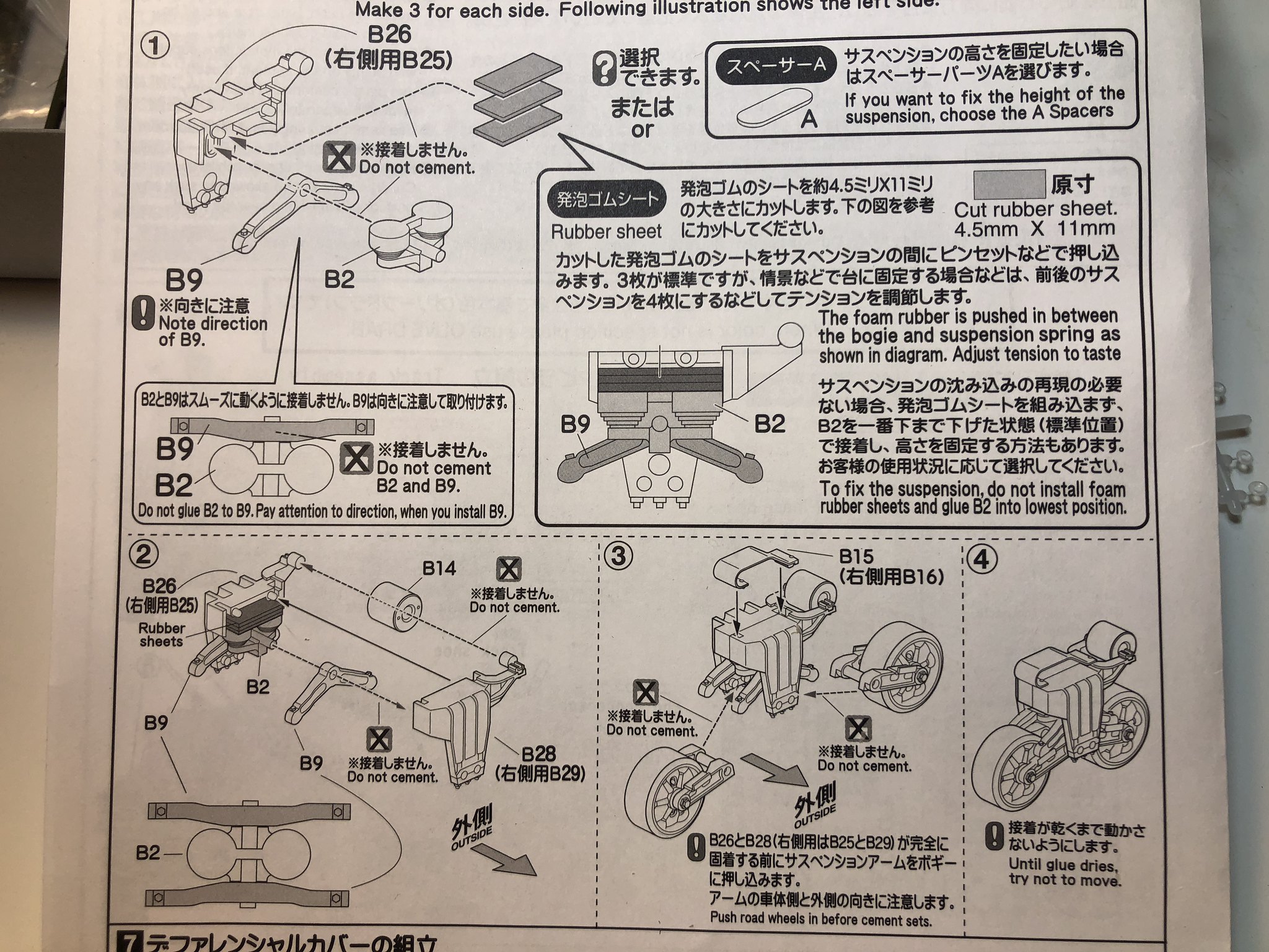
 IMG_9653
 by
russell amott, on Flickr
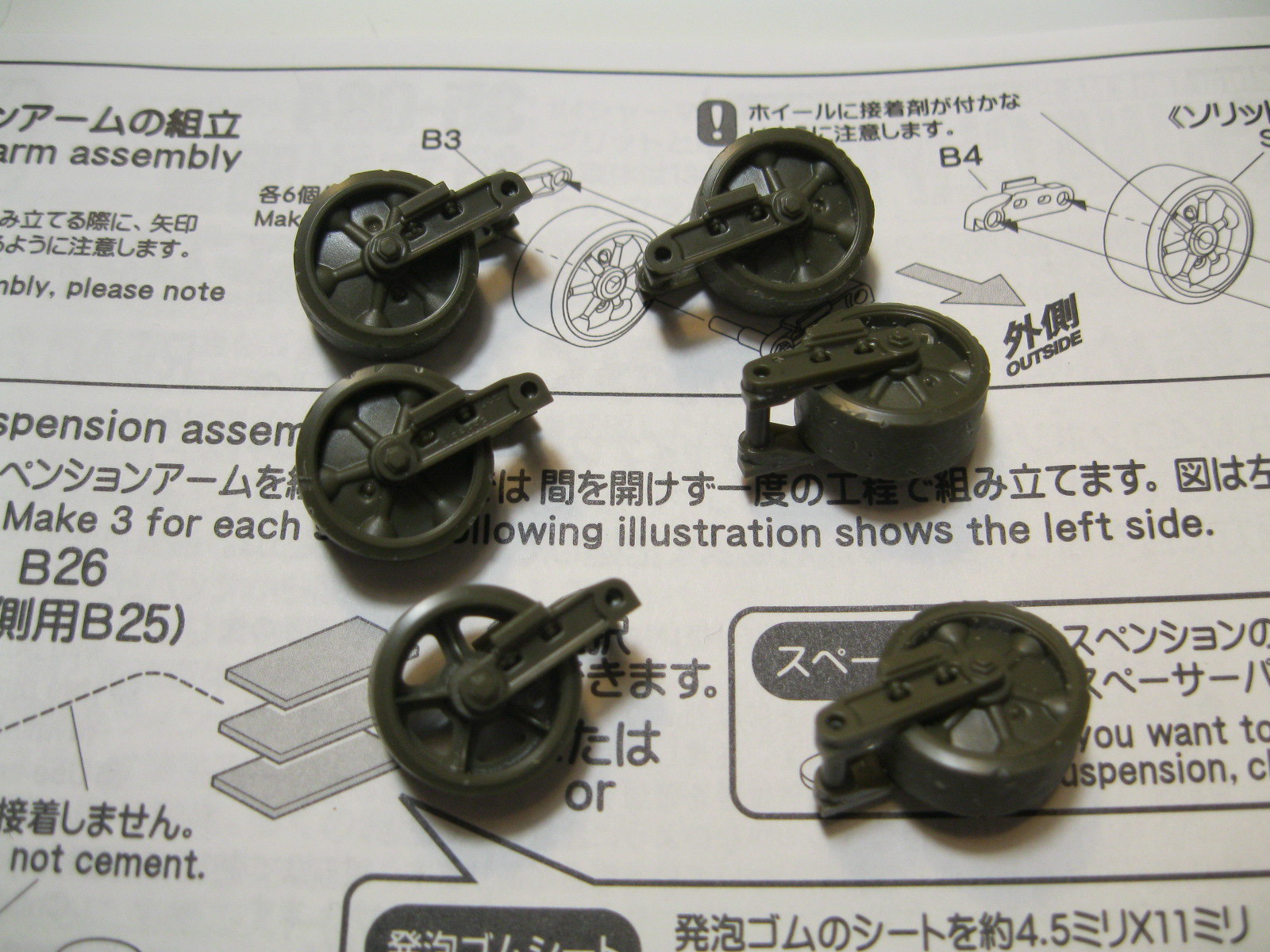
 IMG_9655
 by
russell amott, on Flickr
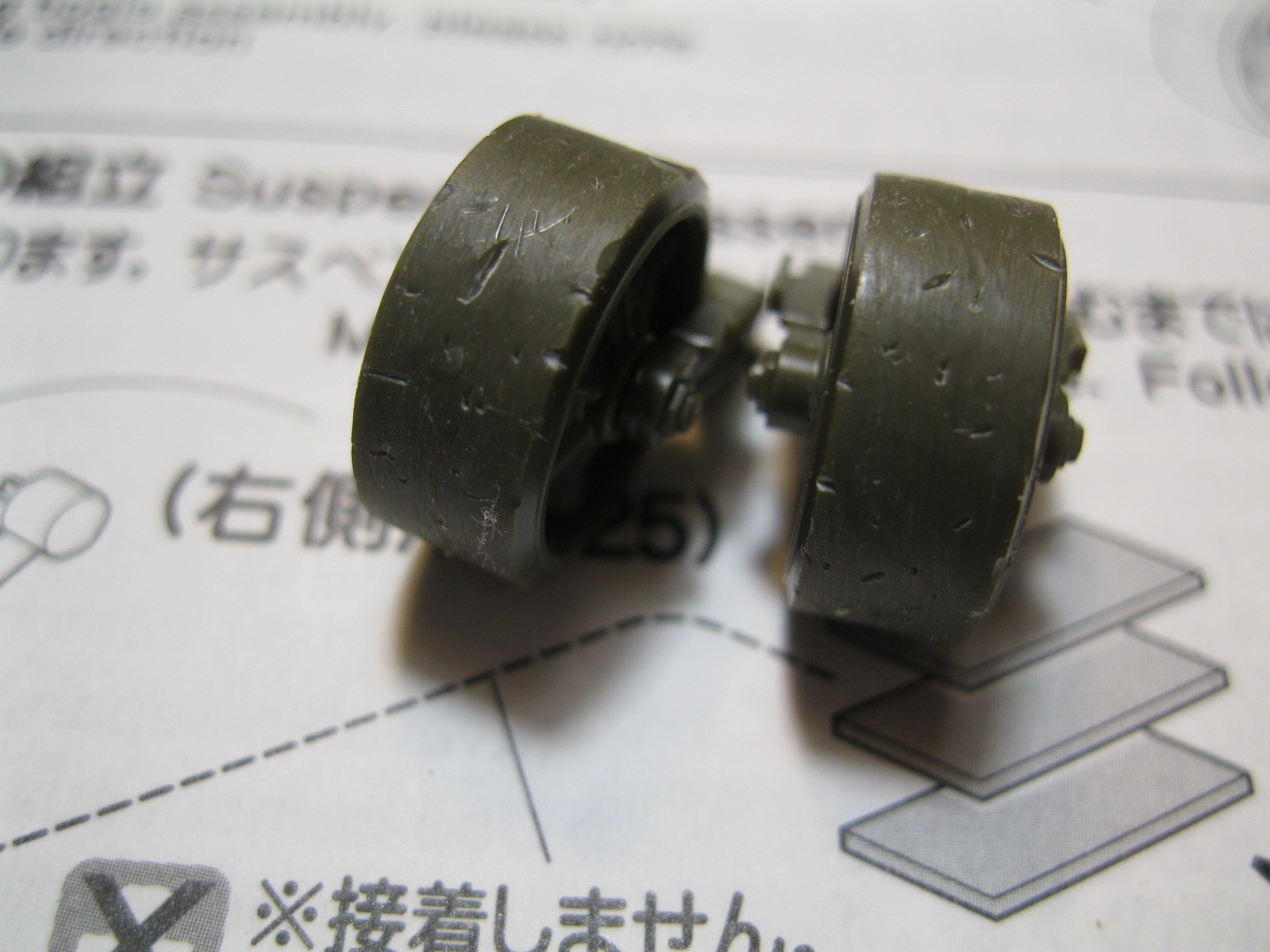
 IMG_9656
 by
russell amott, on Flickr
 IMG_9657
 by
russell amott, on Flickr
 IMG_9658
 by
russell amott, on Flickr
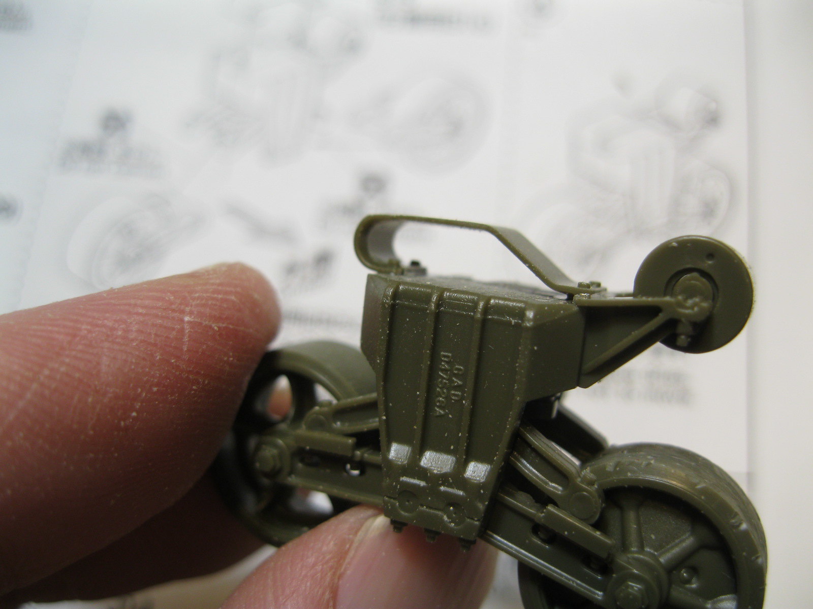
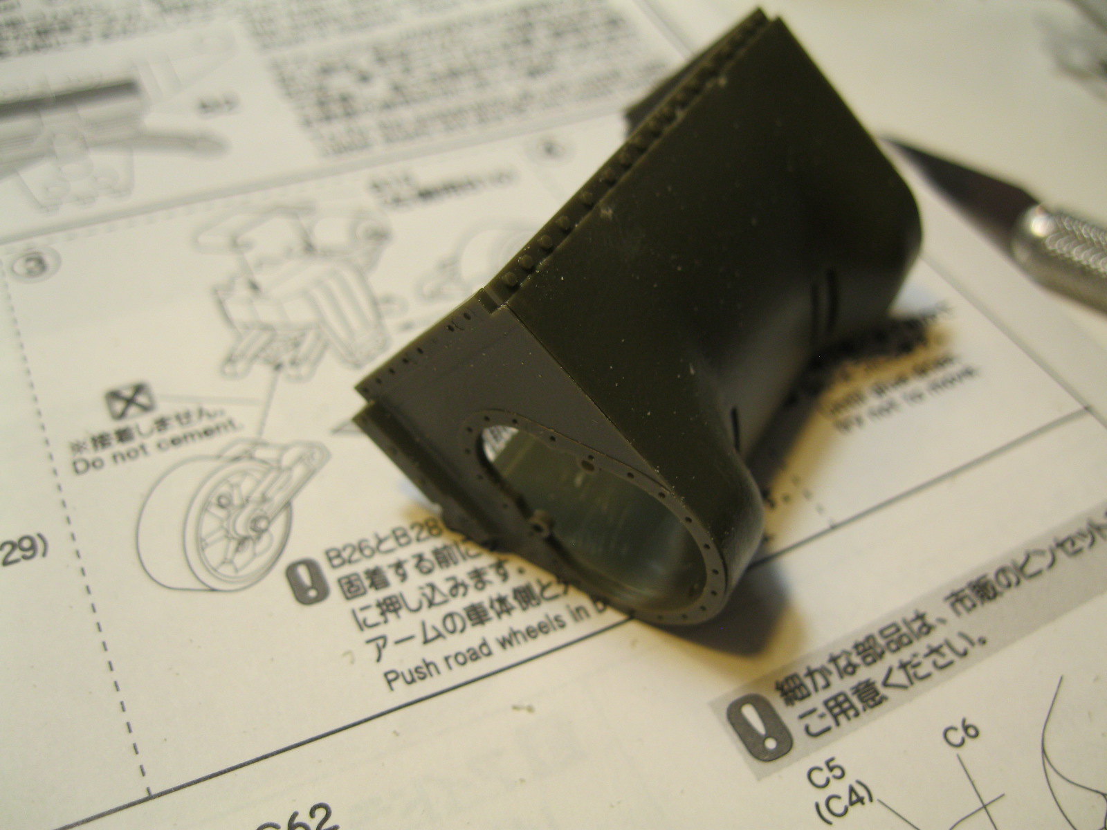
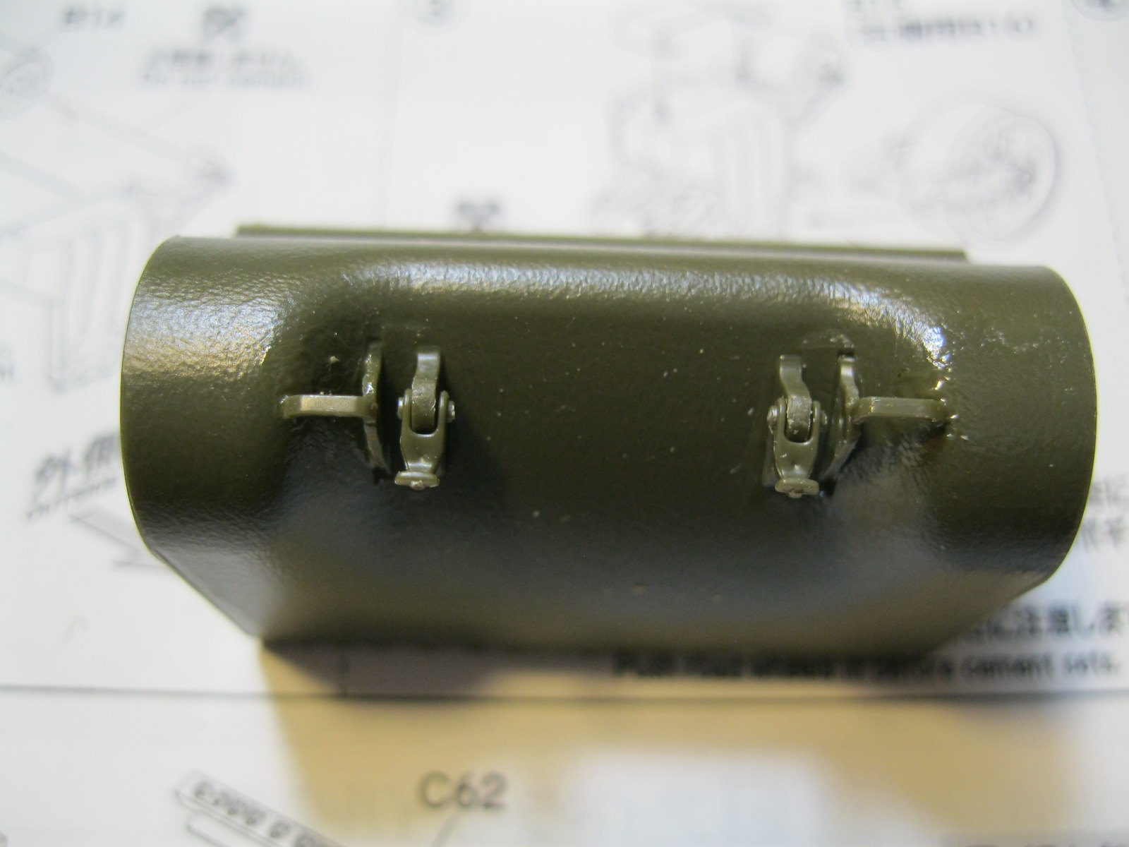
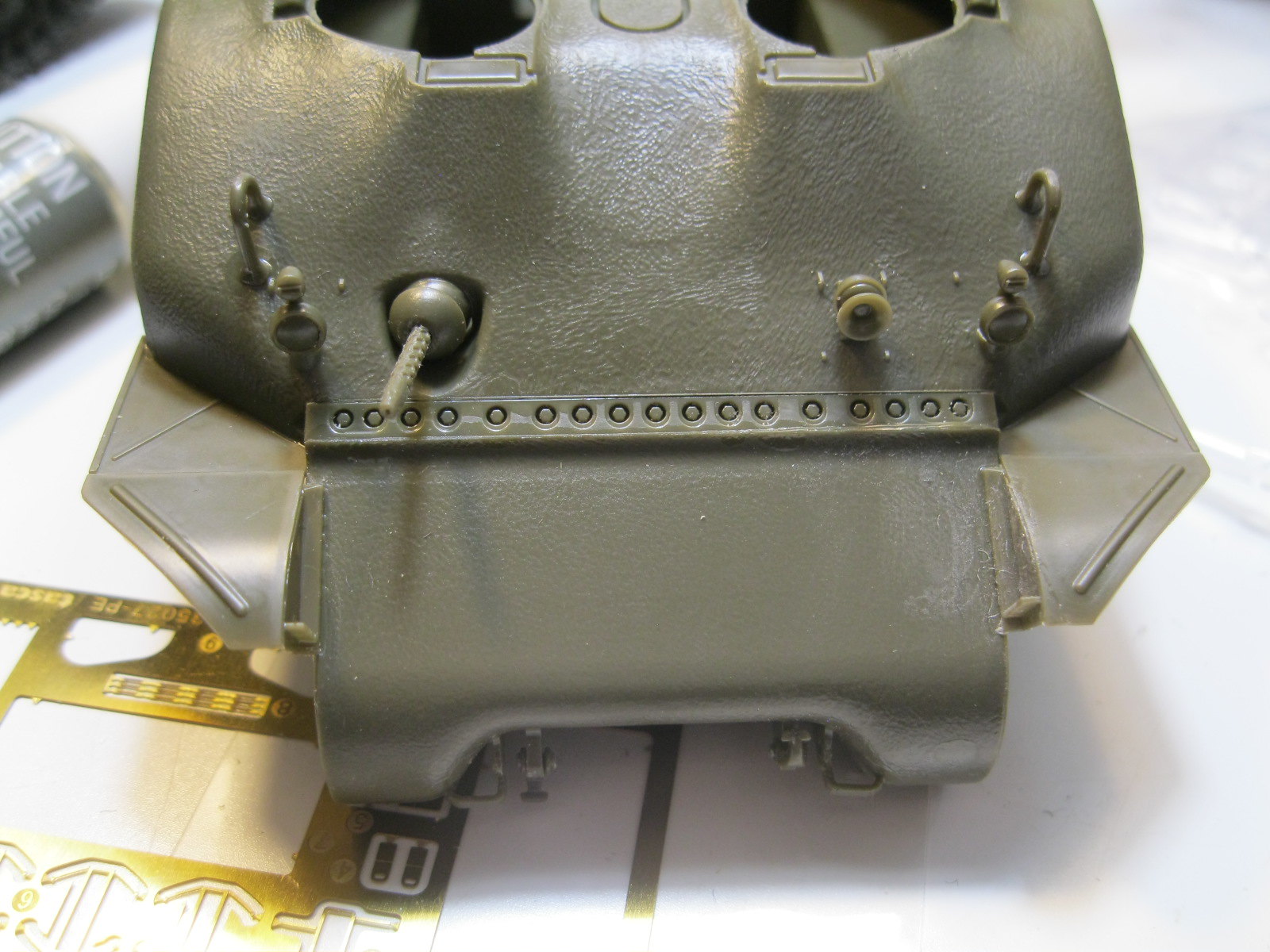
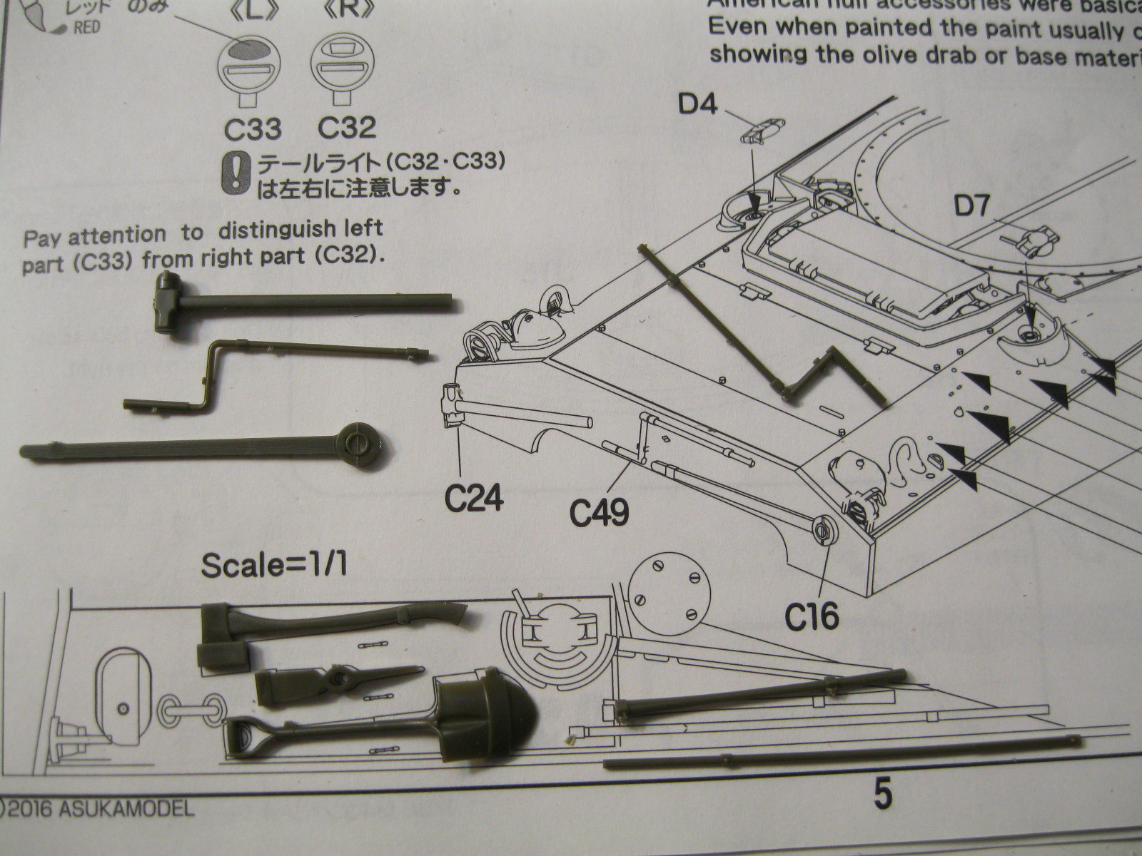
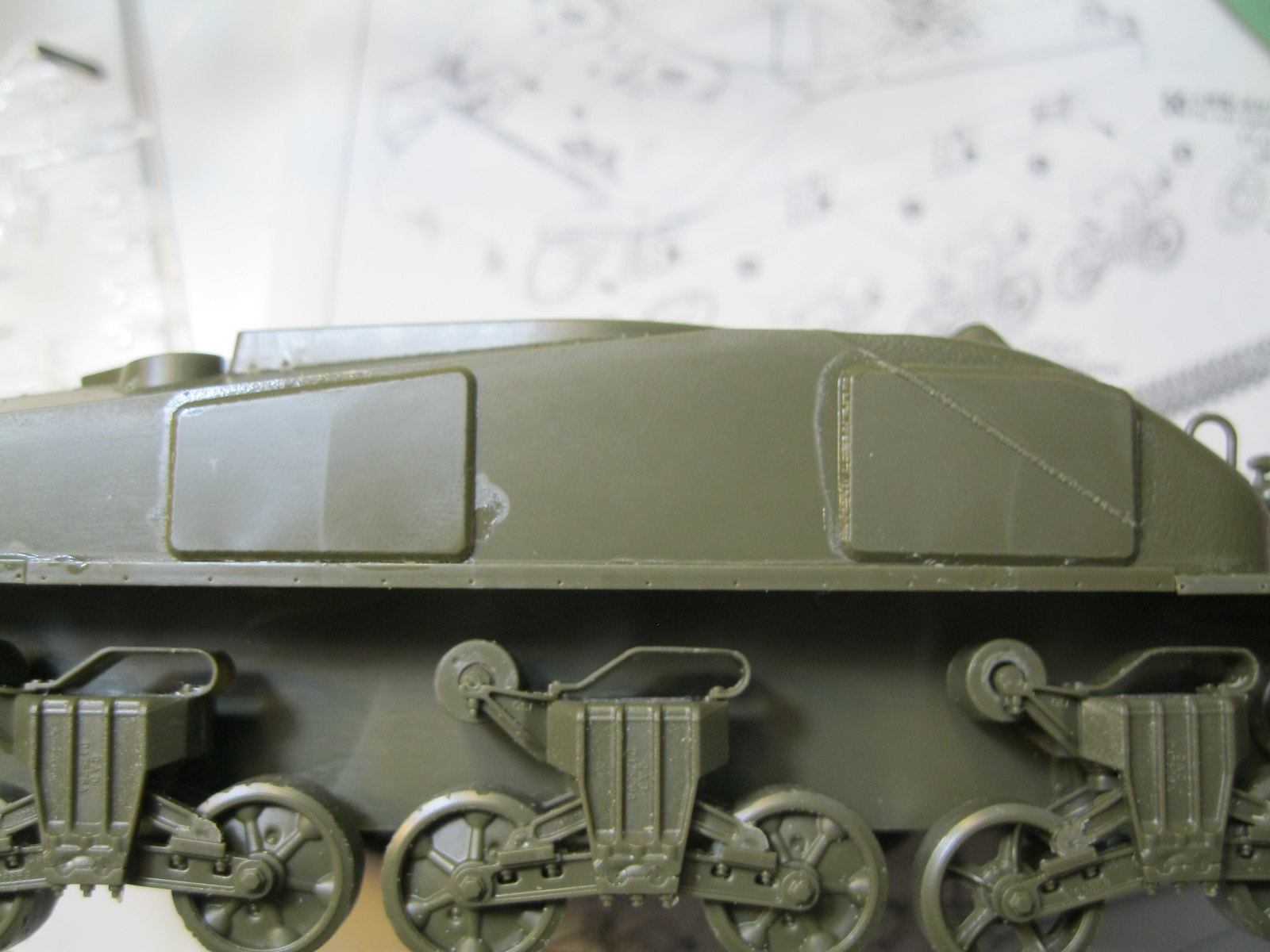
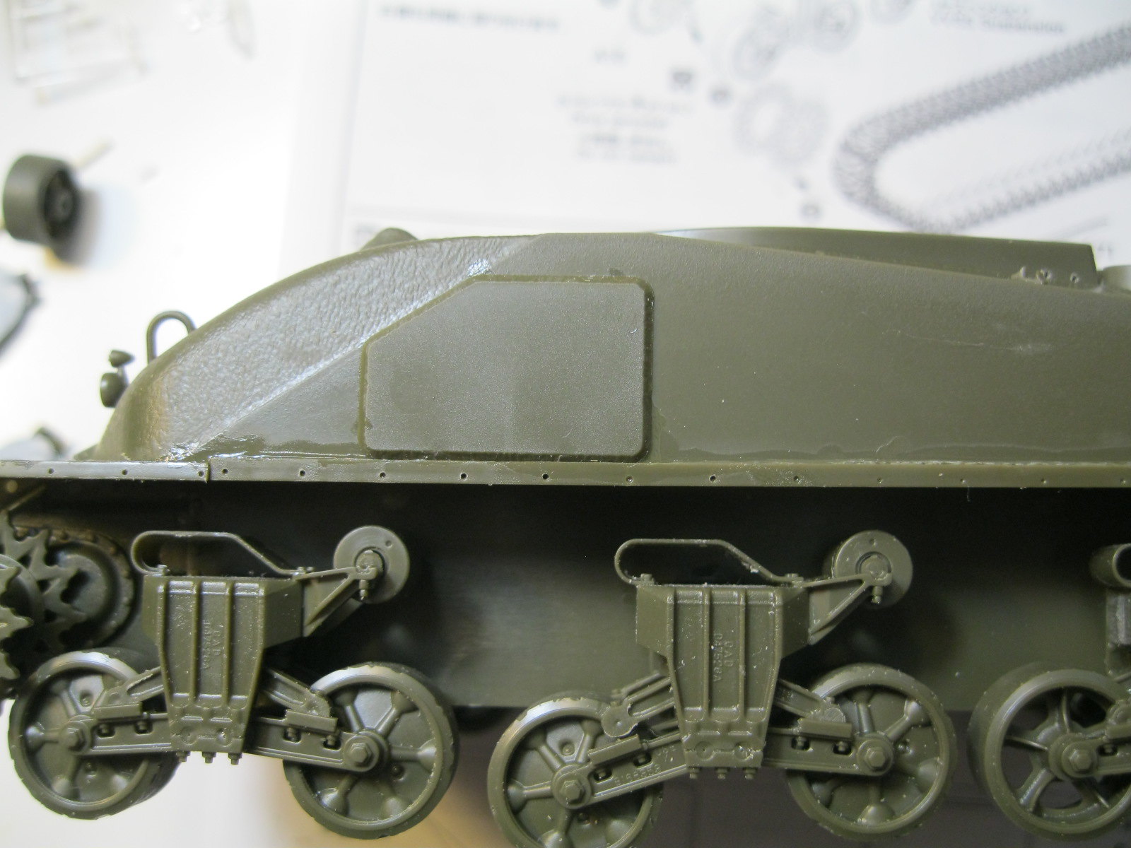
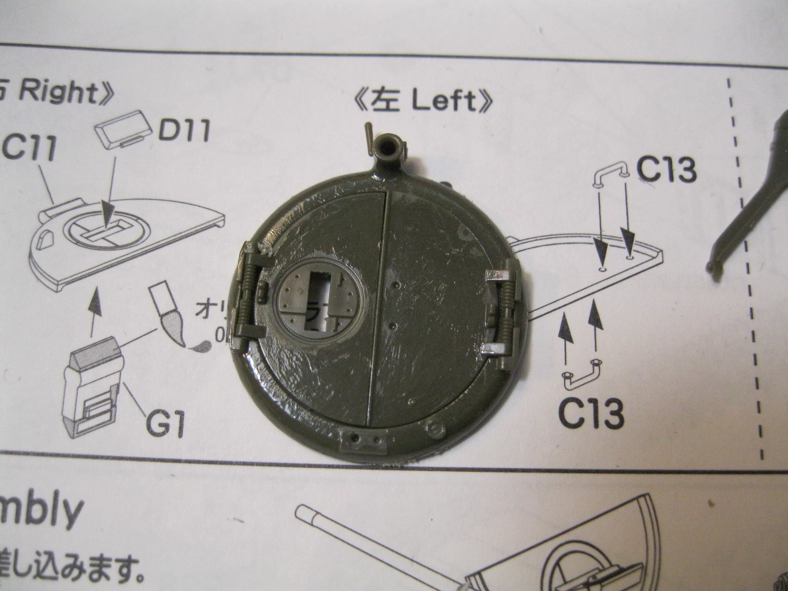
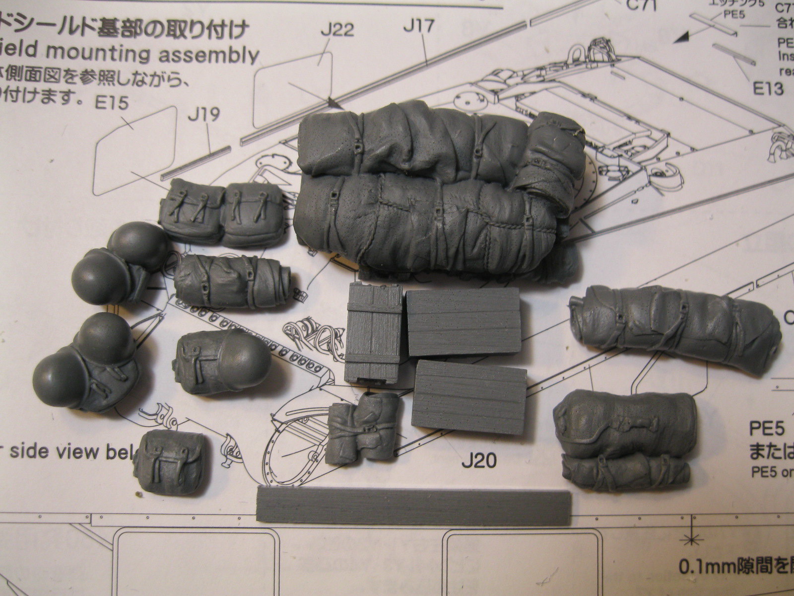
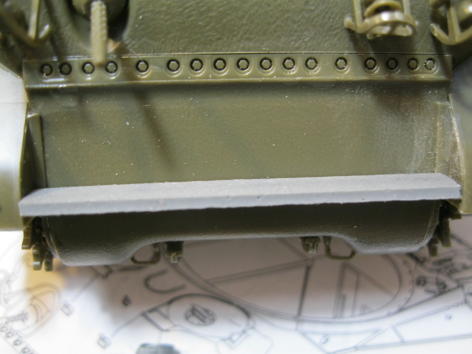
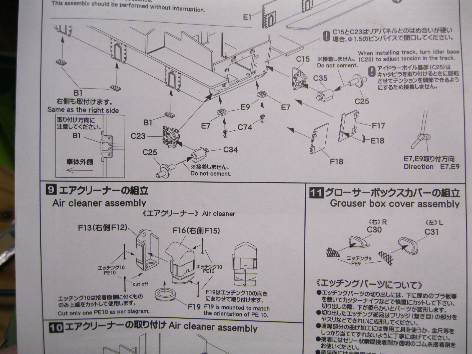
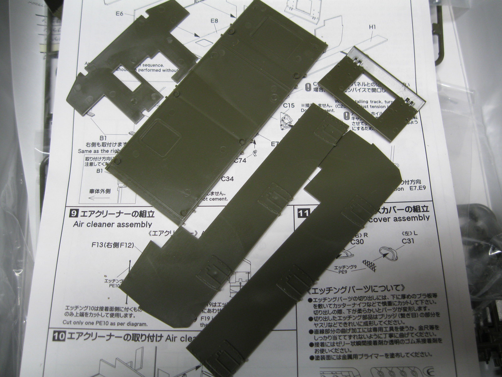
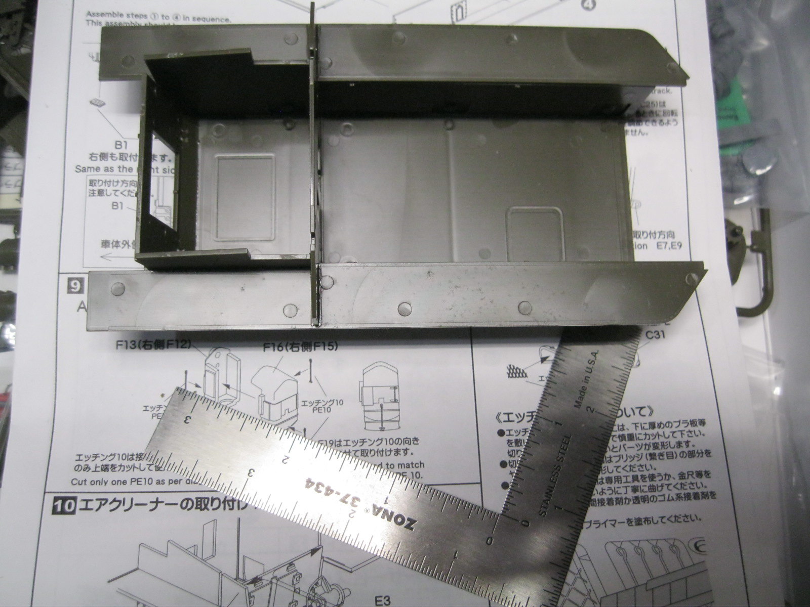
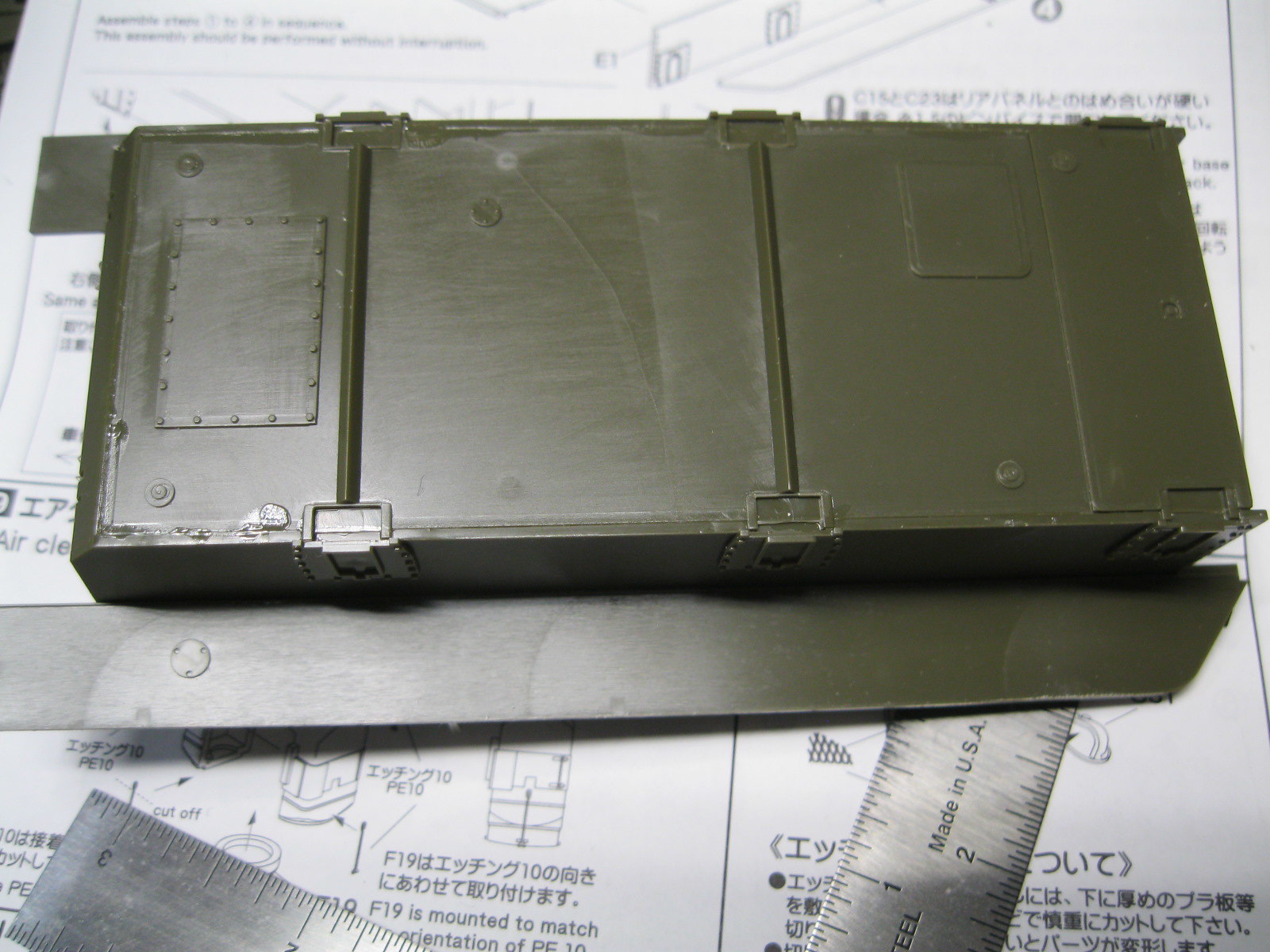
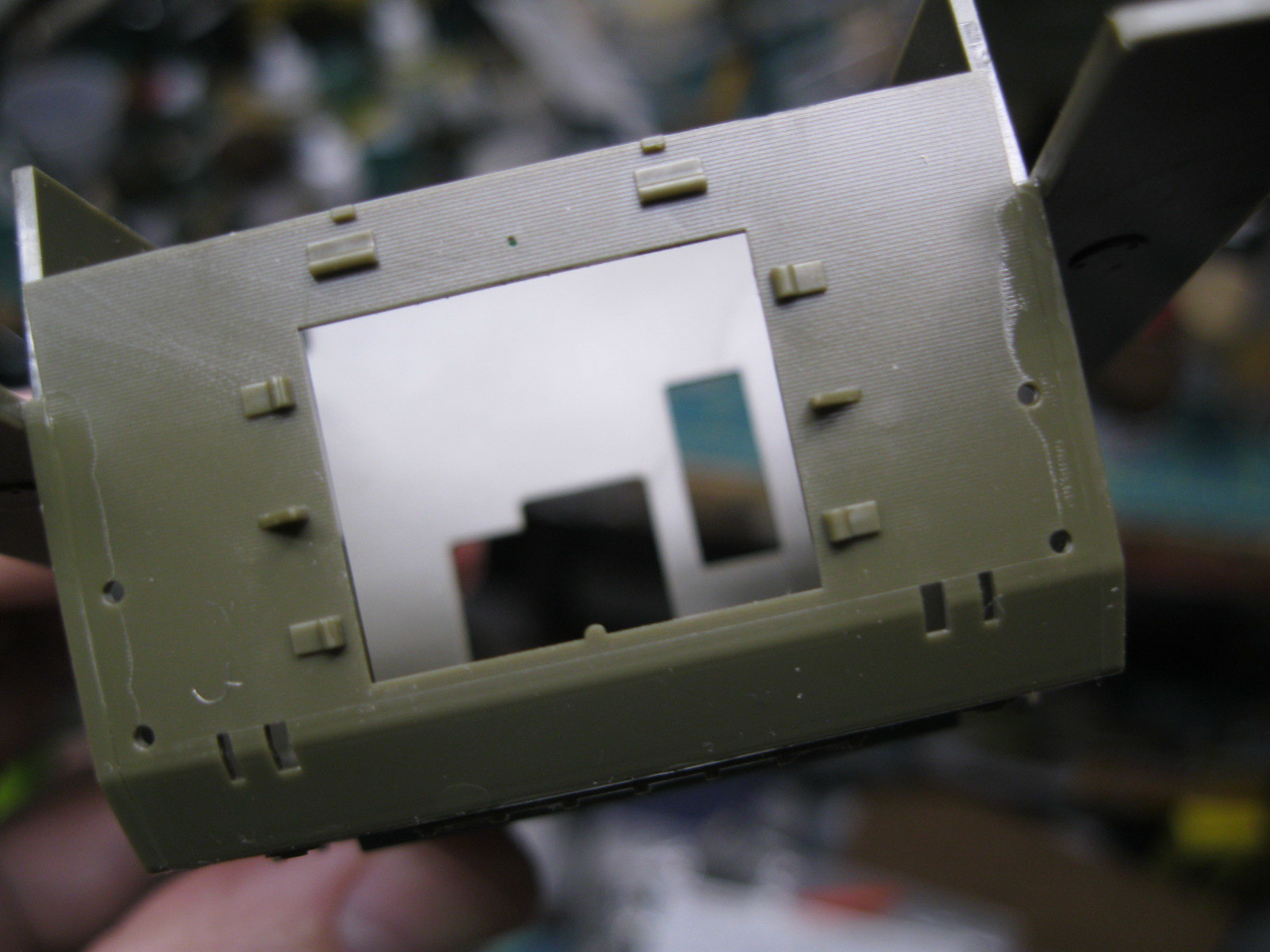
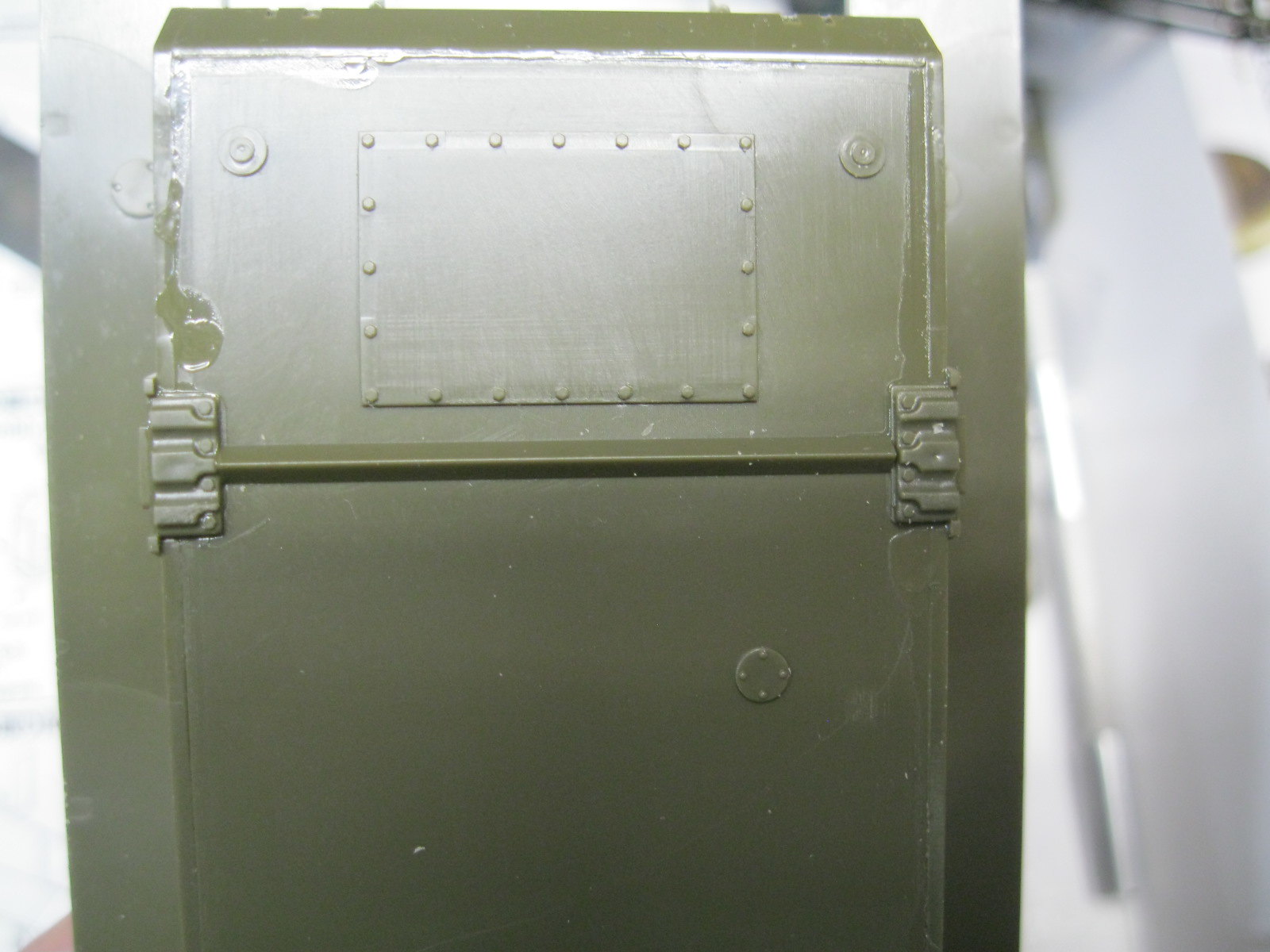
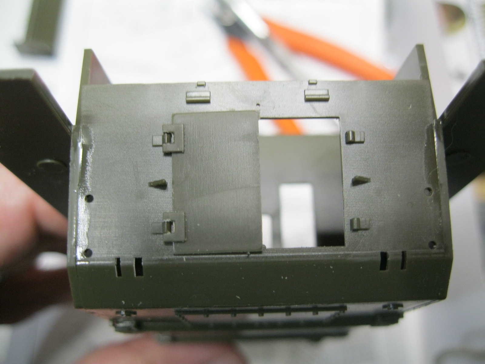
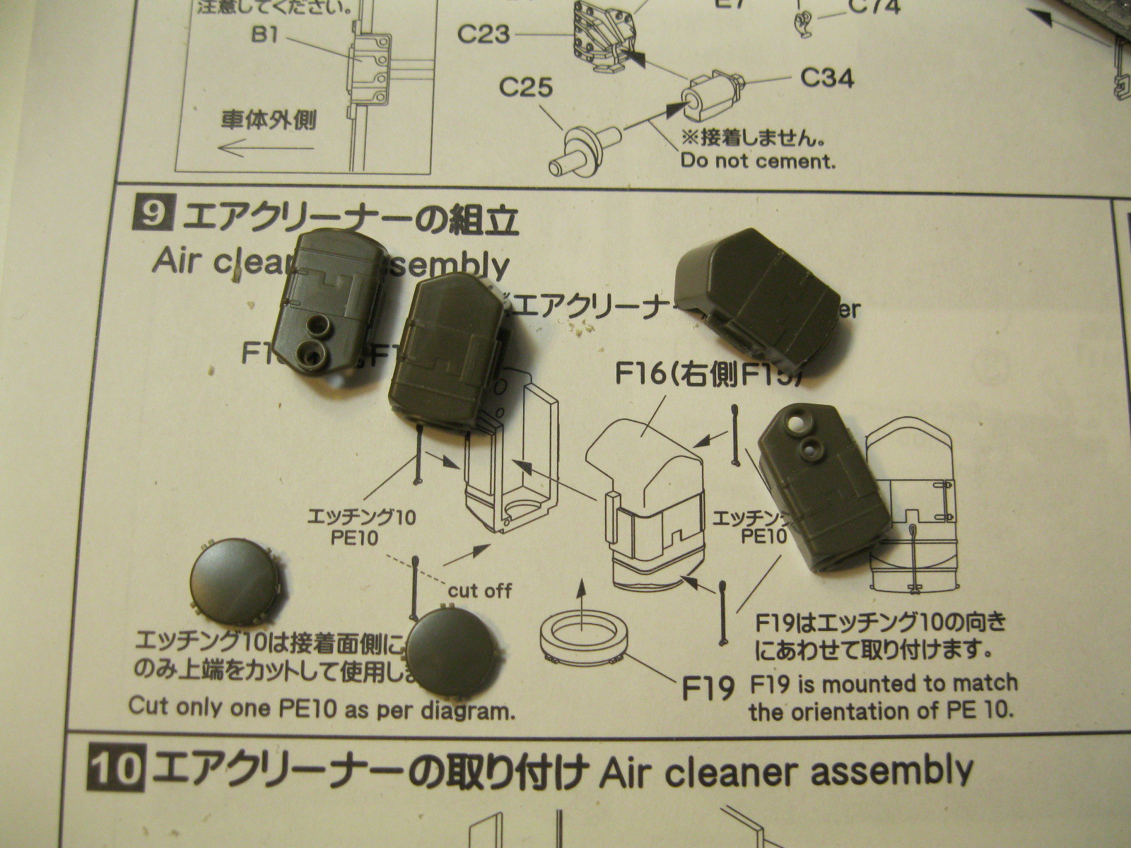
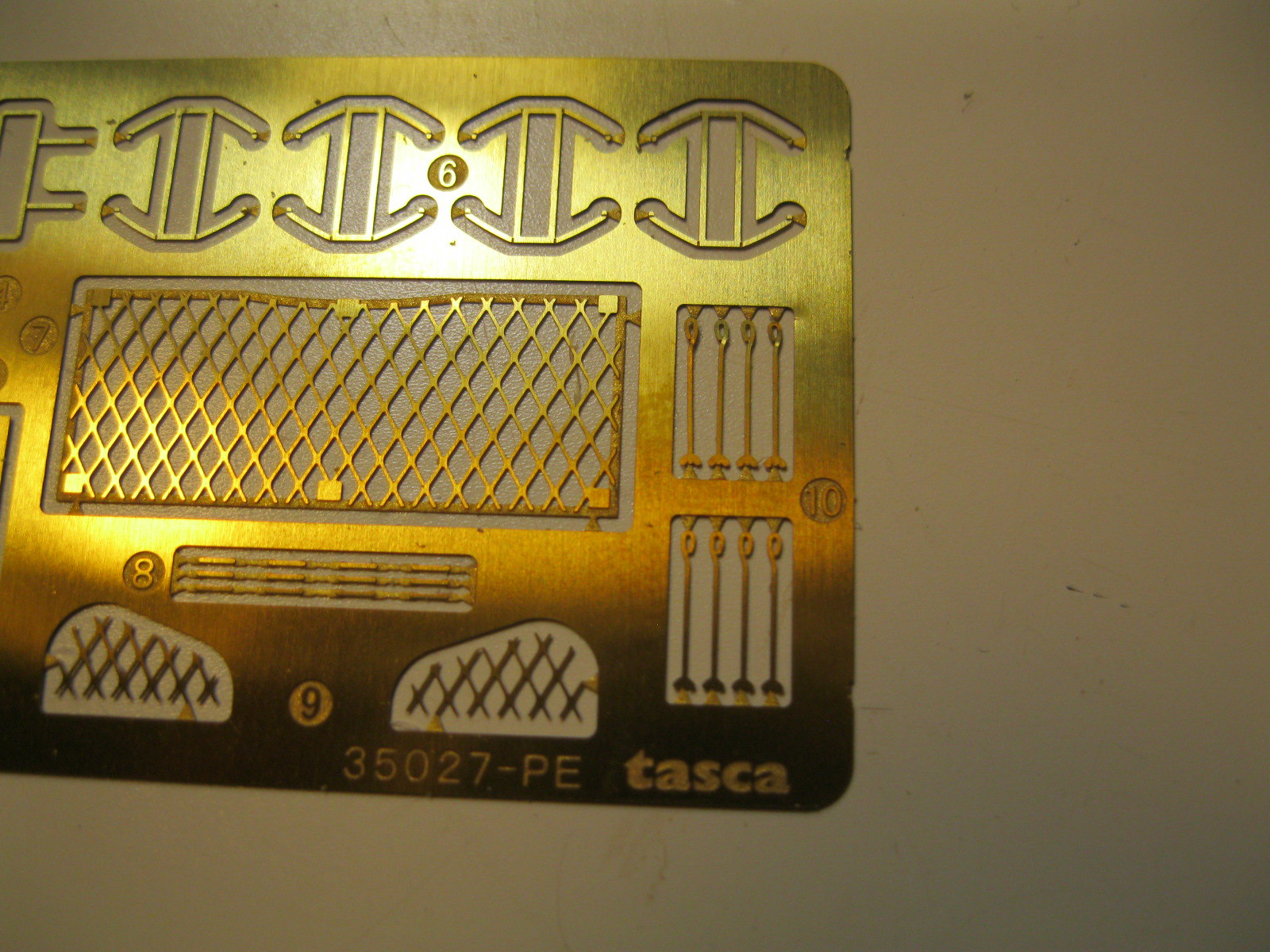
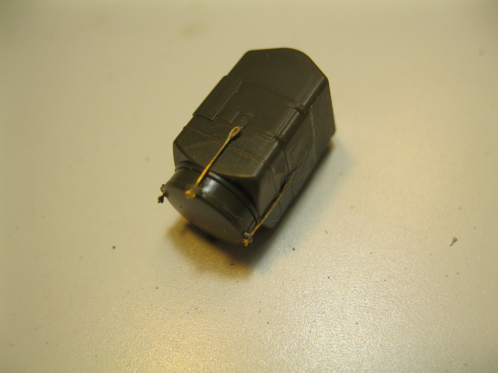
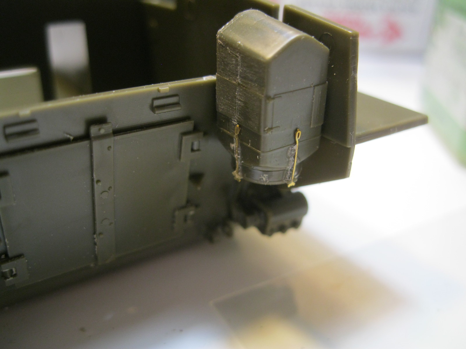
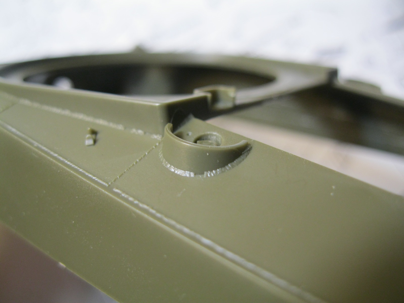
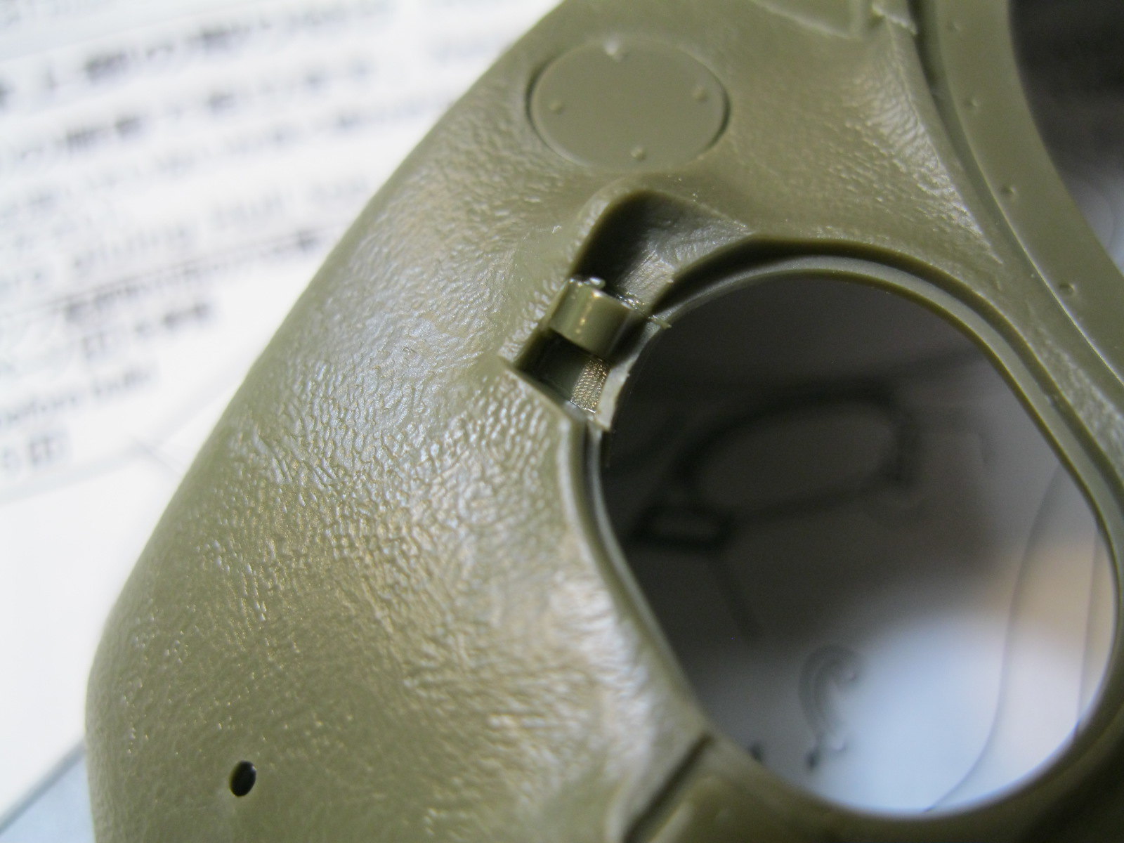
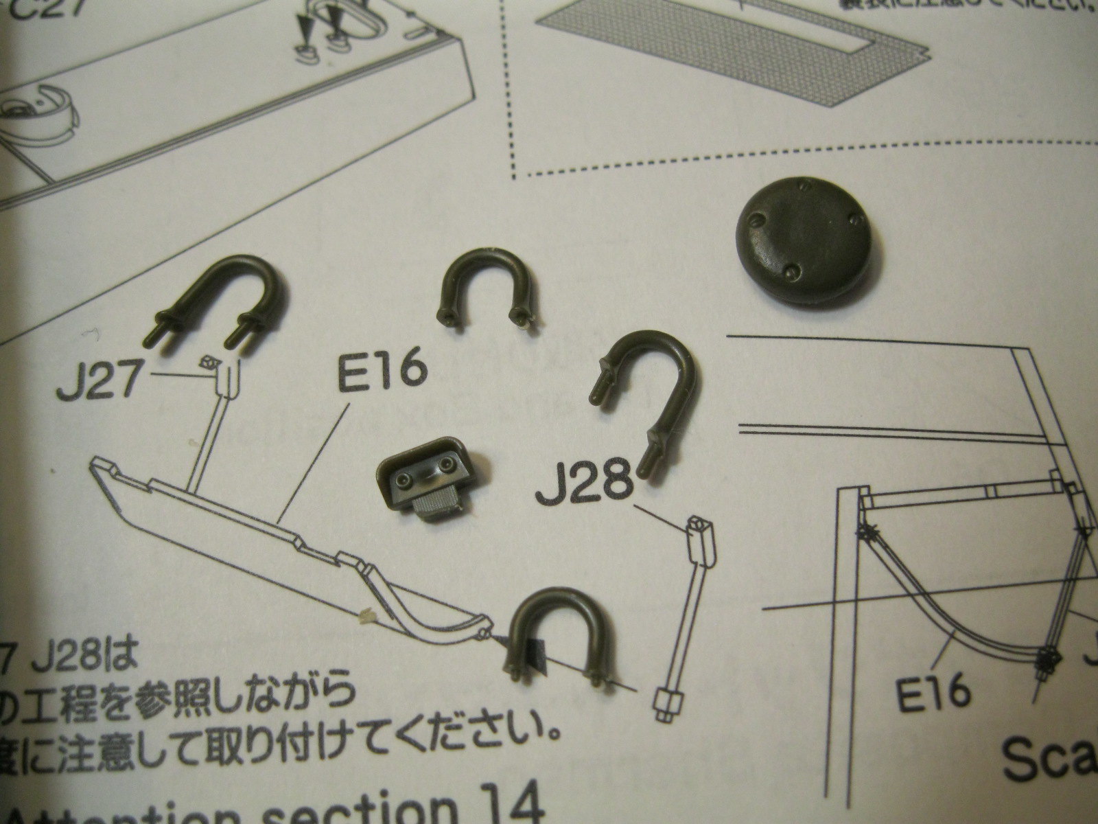
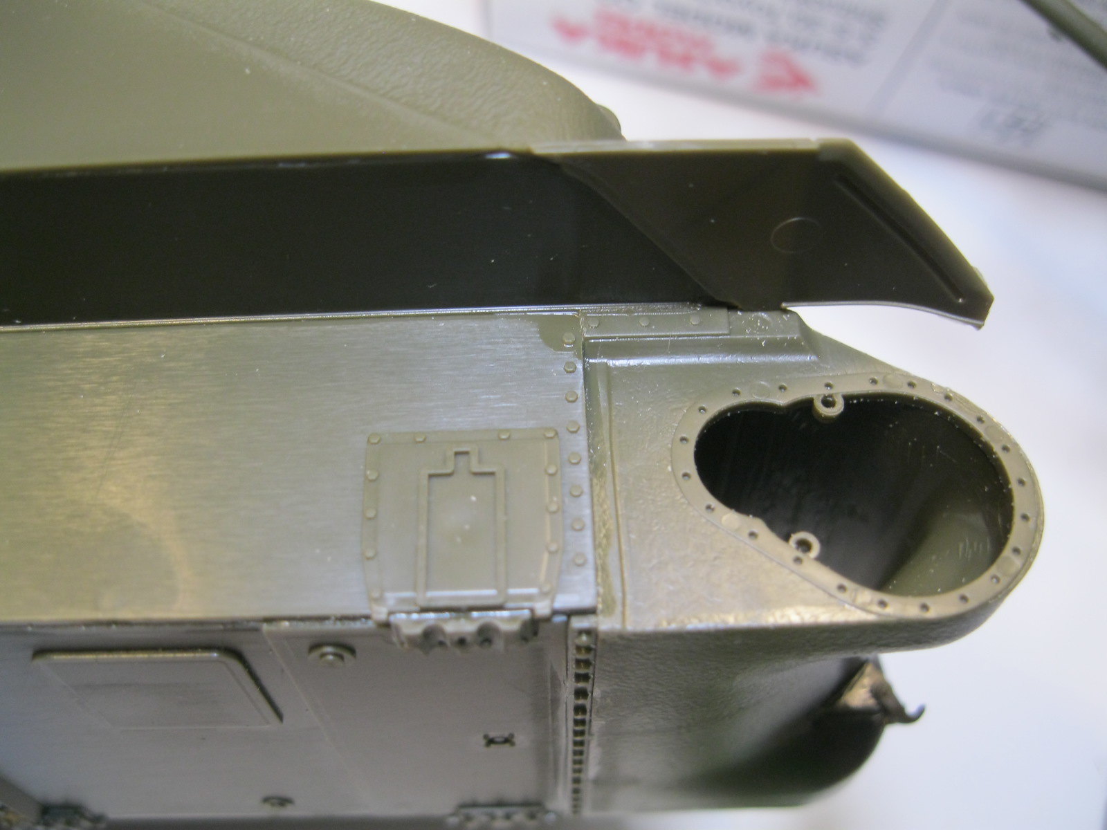
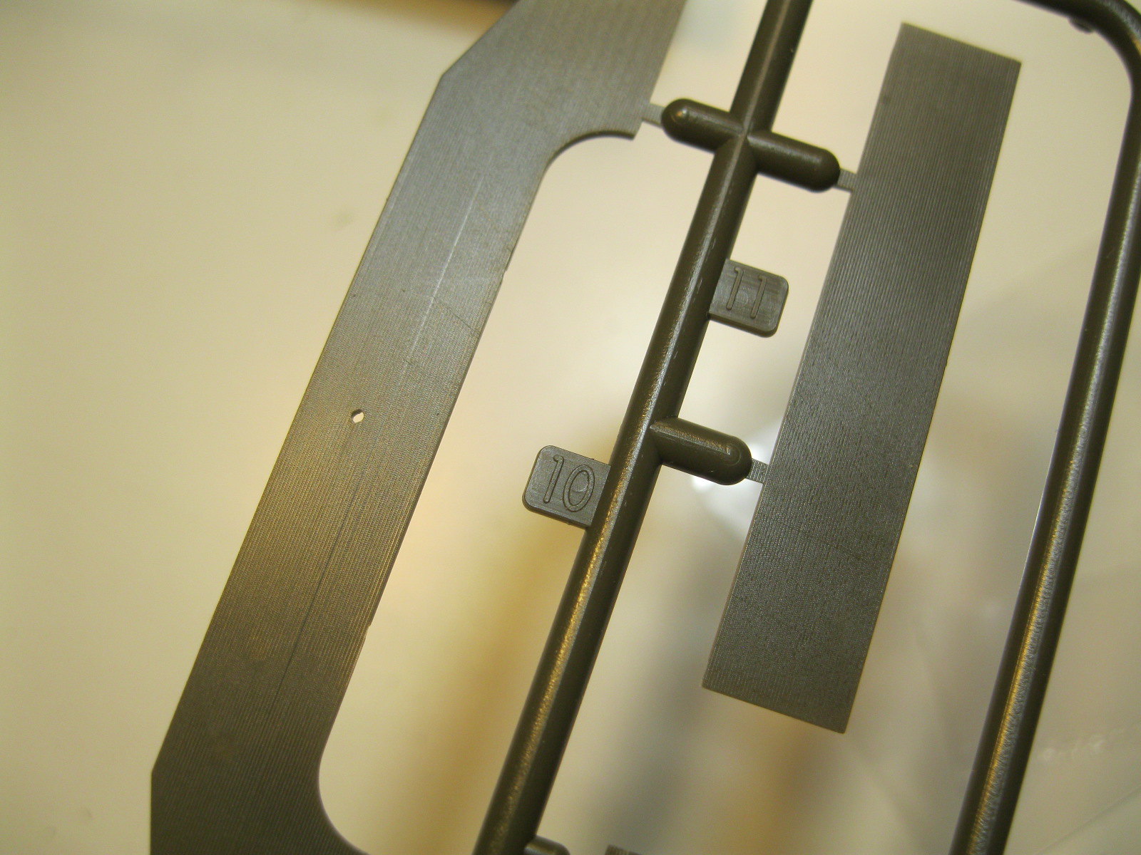
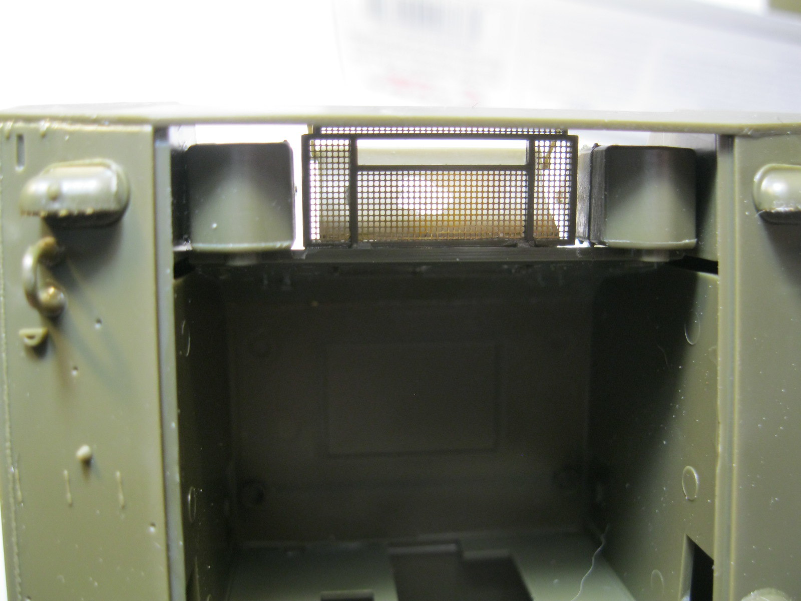
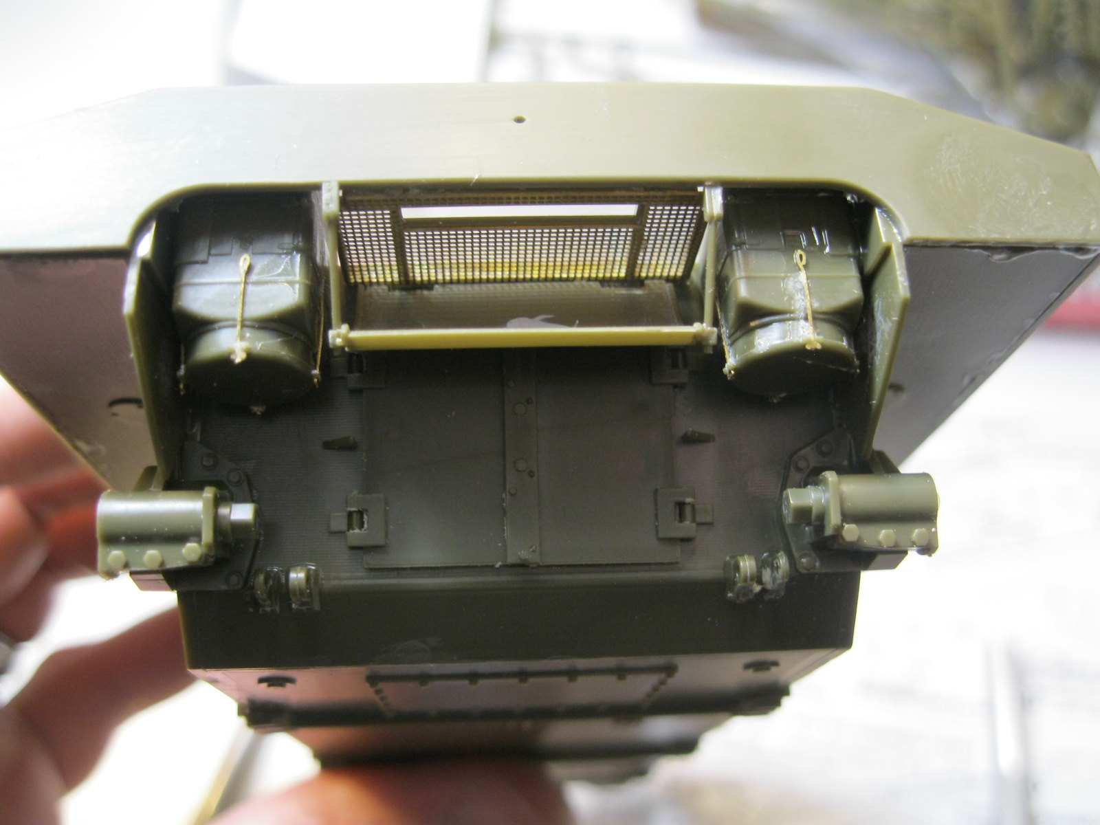
I didn't notice the lines across the rear plate until I was placing it. With the molded on details it isn't easy to clean up. I left it at this point, hoping that the added details will help cover it and no one will really be looking up the backside of the tank when it is done. Next came the placing of the small details on the rear and bottom. The engine access doors required some careful filing to get them to fit properly, something I remember from my previous Tasca kit. There are also some small sink marks visible on many of the little parts. Those on the hull bottom won't be seen. The air filters require some careful cleanup of the join seam and get small etch clamps. My CA glue was clumping and leaving little web strands so the clips look a little sloppy. I tossed that bottle and got a new one so the rest of the etch will go on cleanly.
 IMG_9659
 by
russell amott, on Flickr
 IMG_9660
 by
russell amott, on Flickr
 IMG_9661
 by
russell amott, on Flickr
 IMG_9662
 by
russell amott, on Flickr
 IMG_9663
 by
russell amott, on Flickr
 IMG_9664
 by
russell amott, on Flickr
 IMG_9665
 by
russell amott, on Flickr
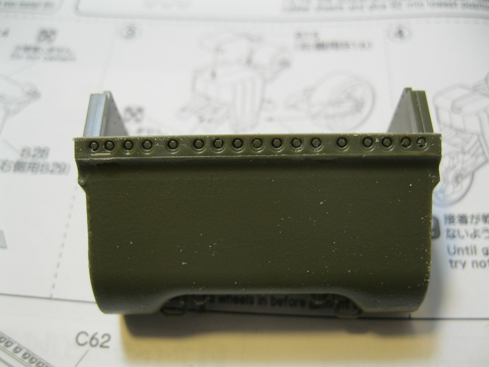
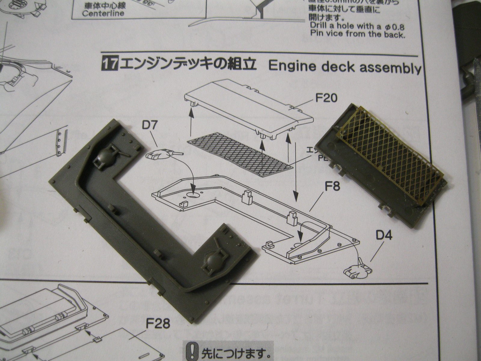
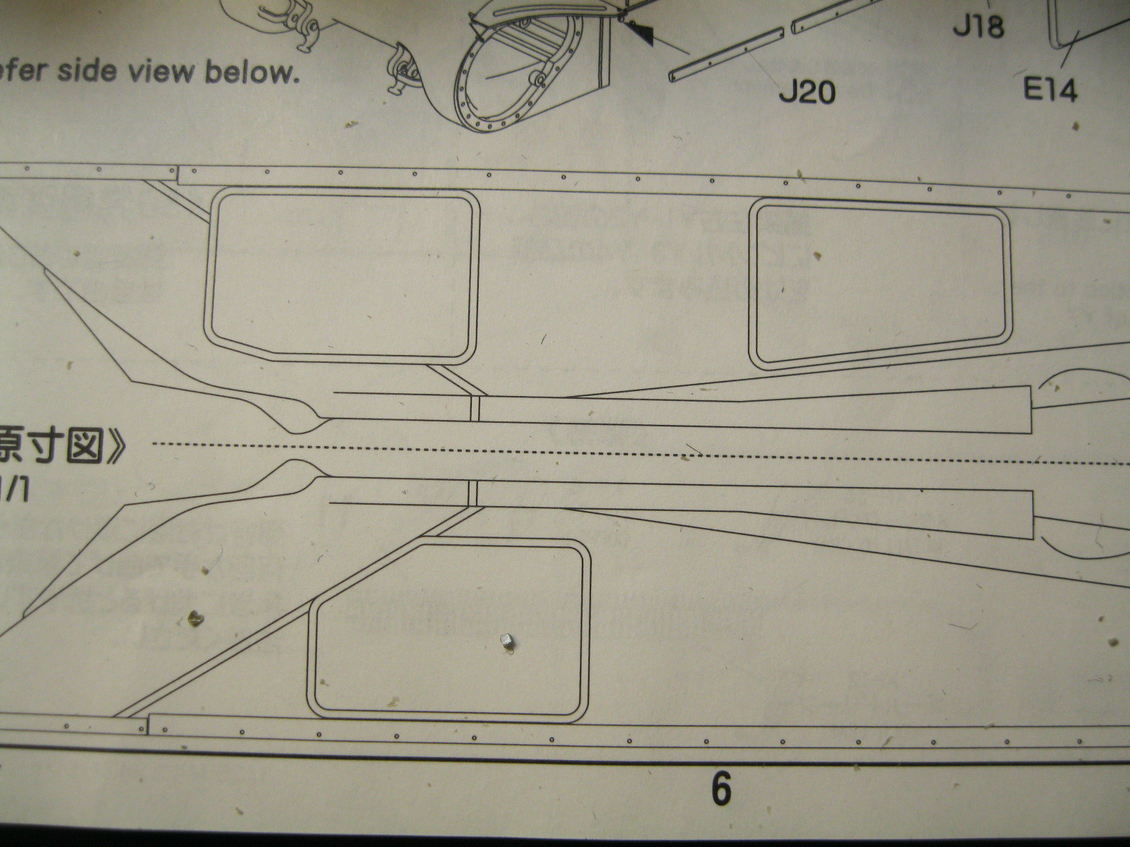
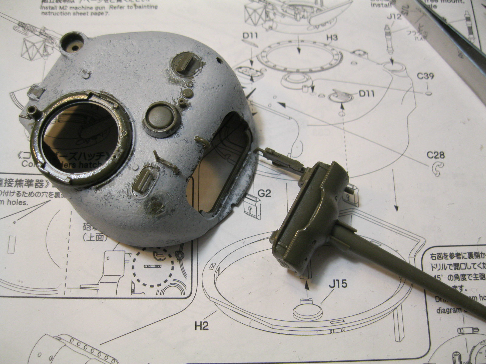
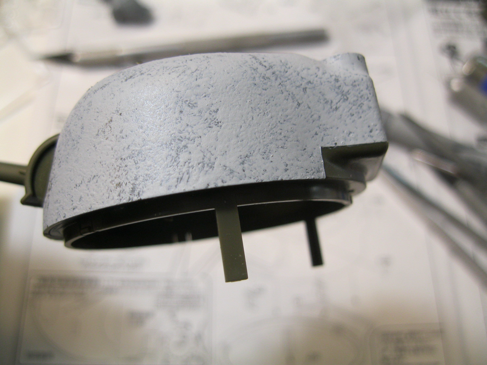
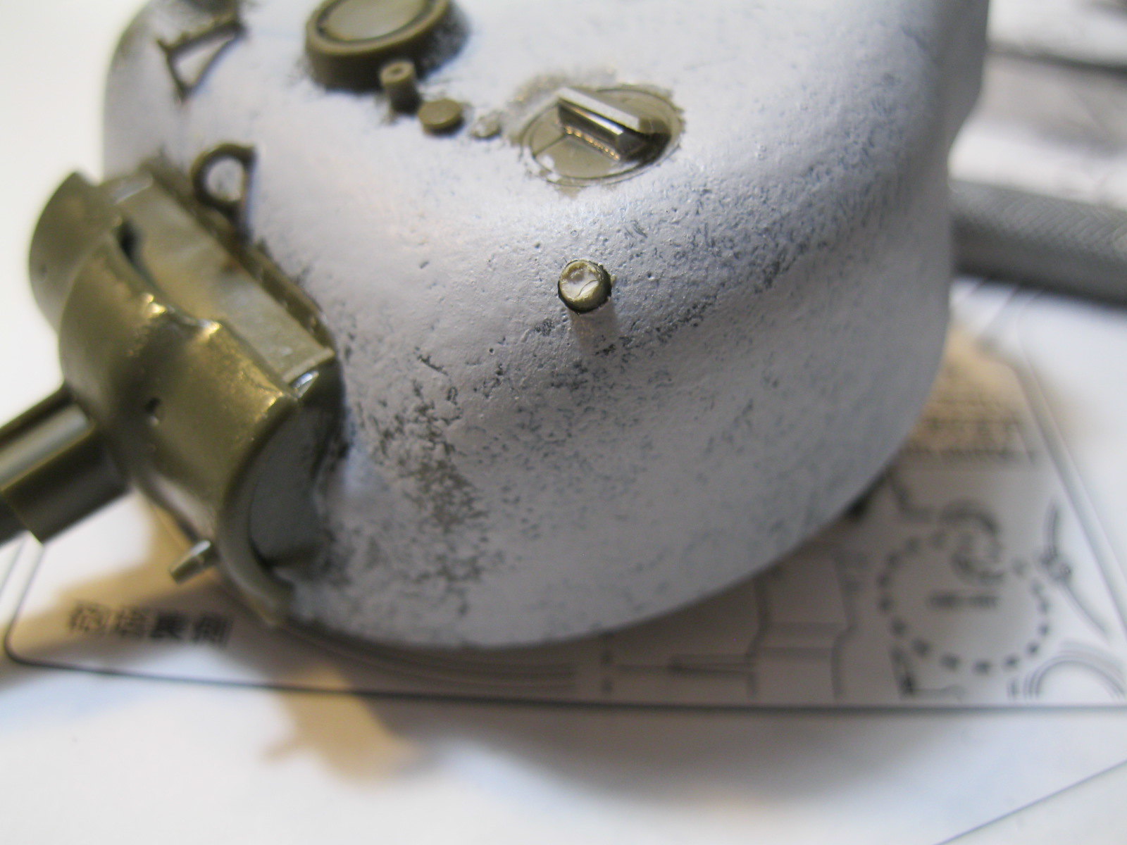
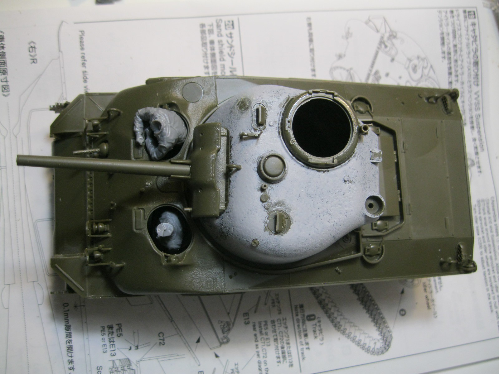
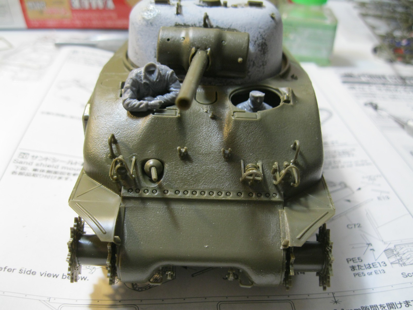
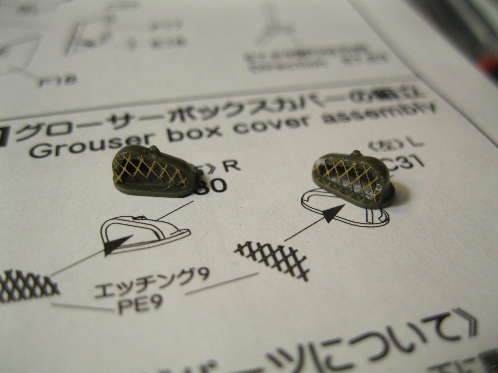
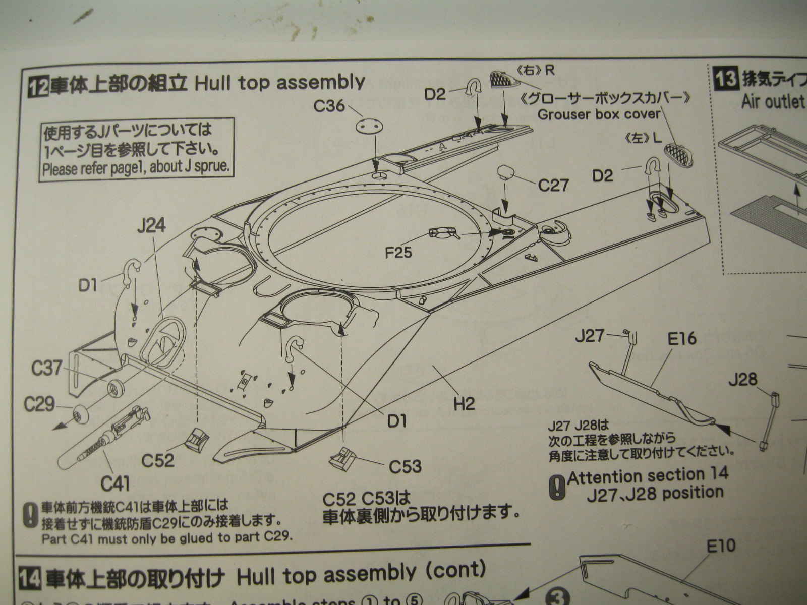
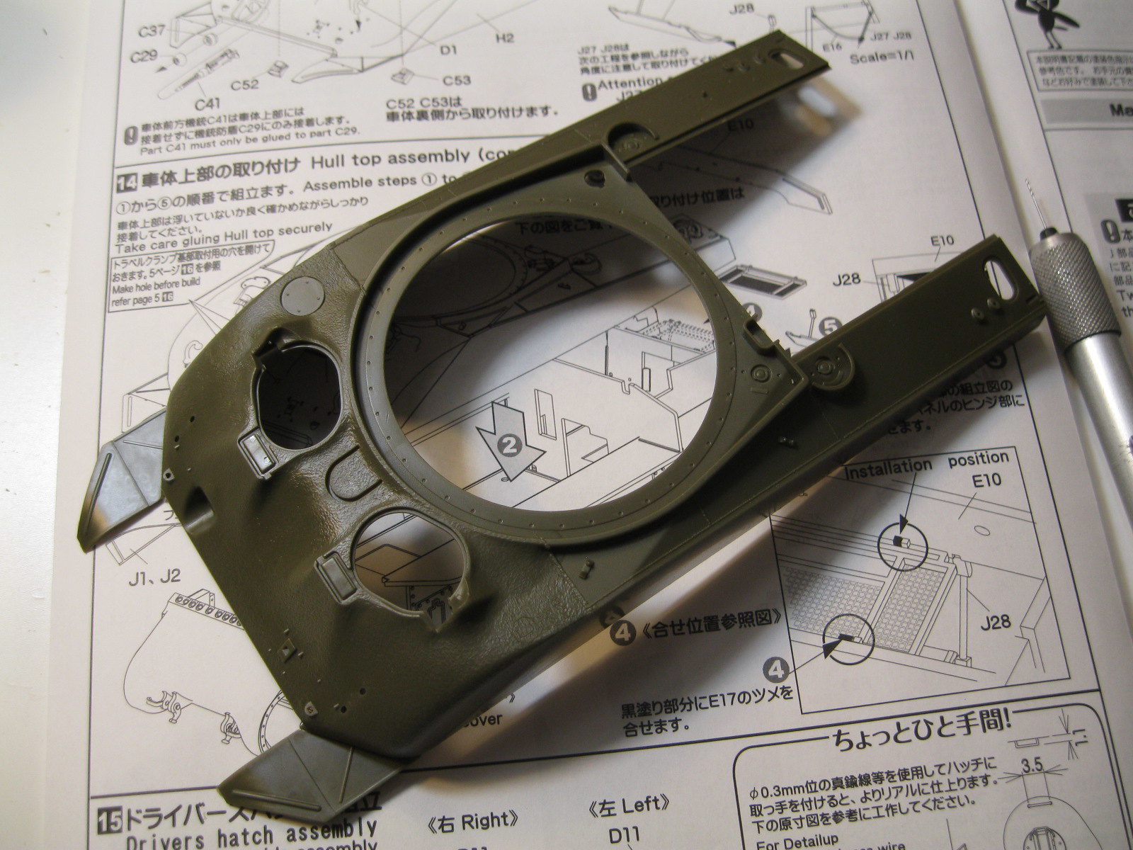
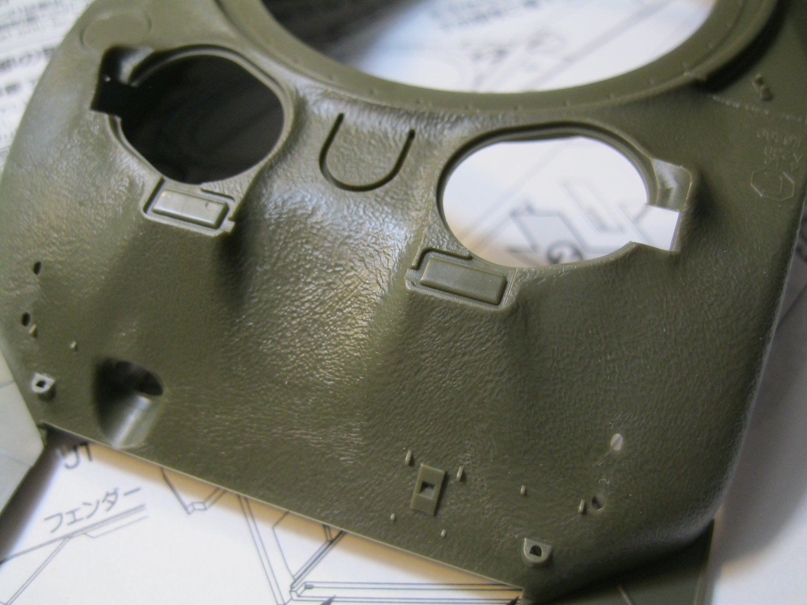
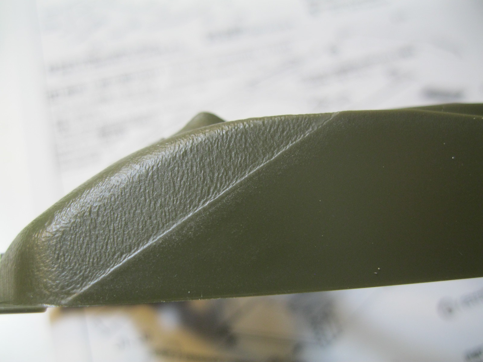
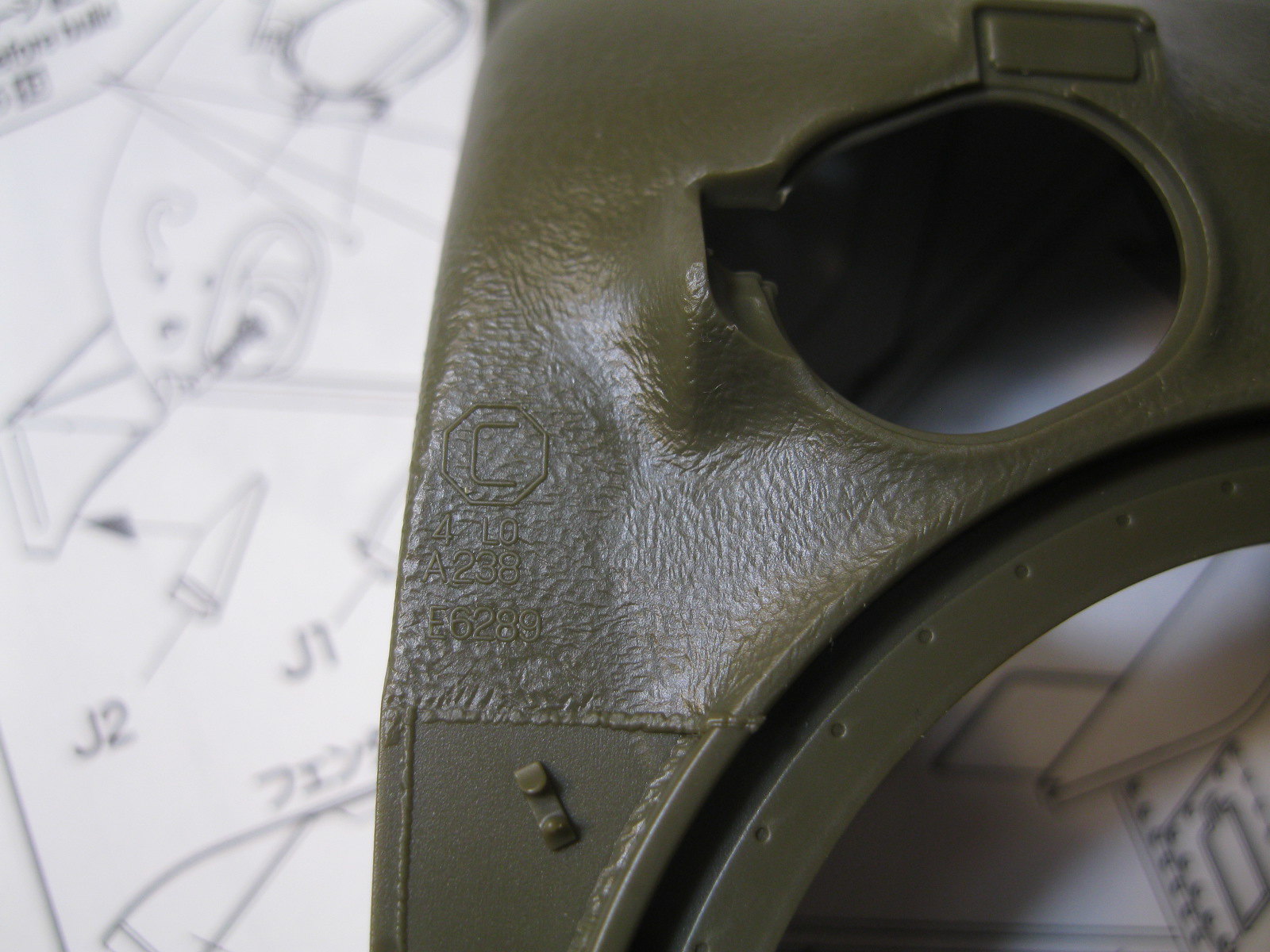
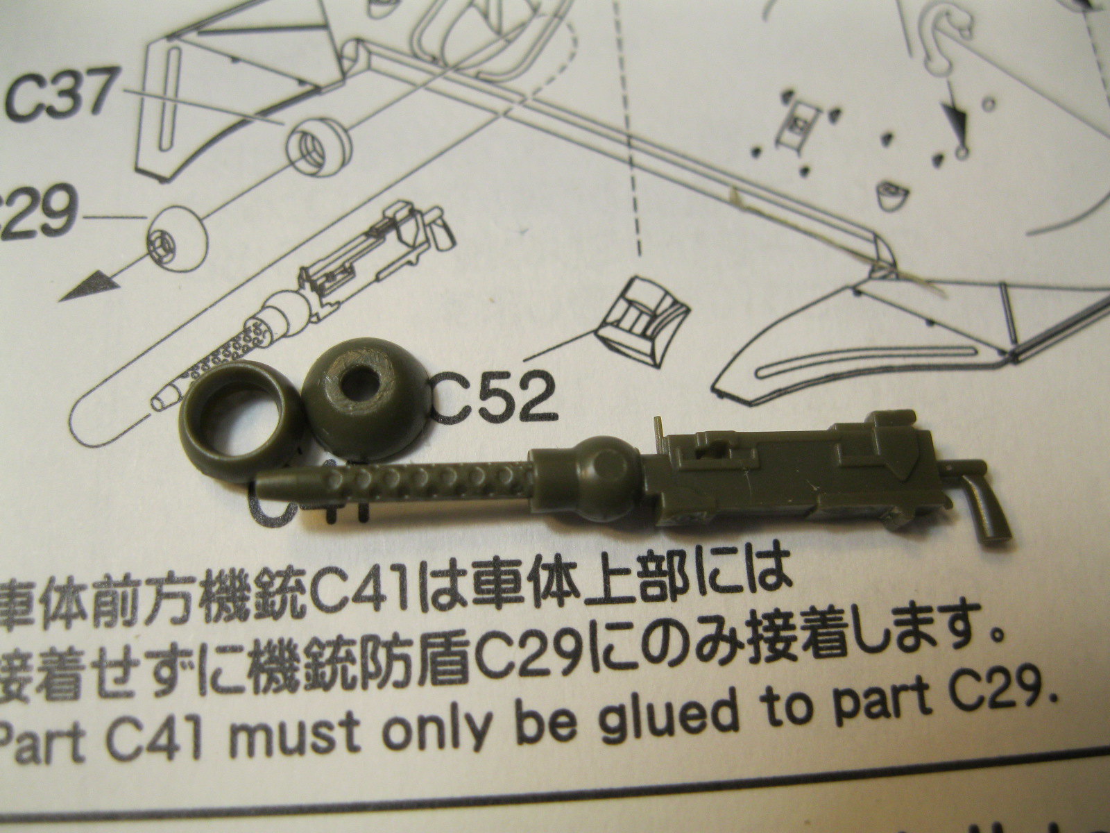
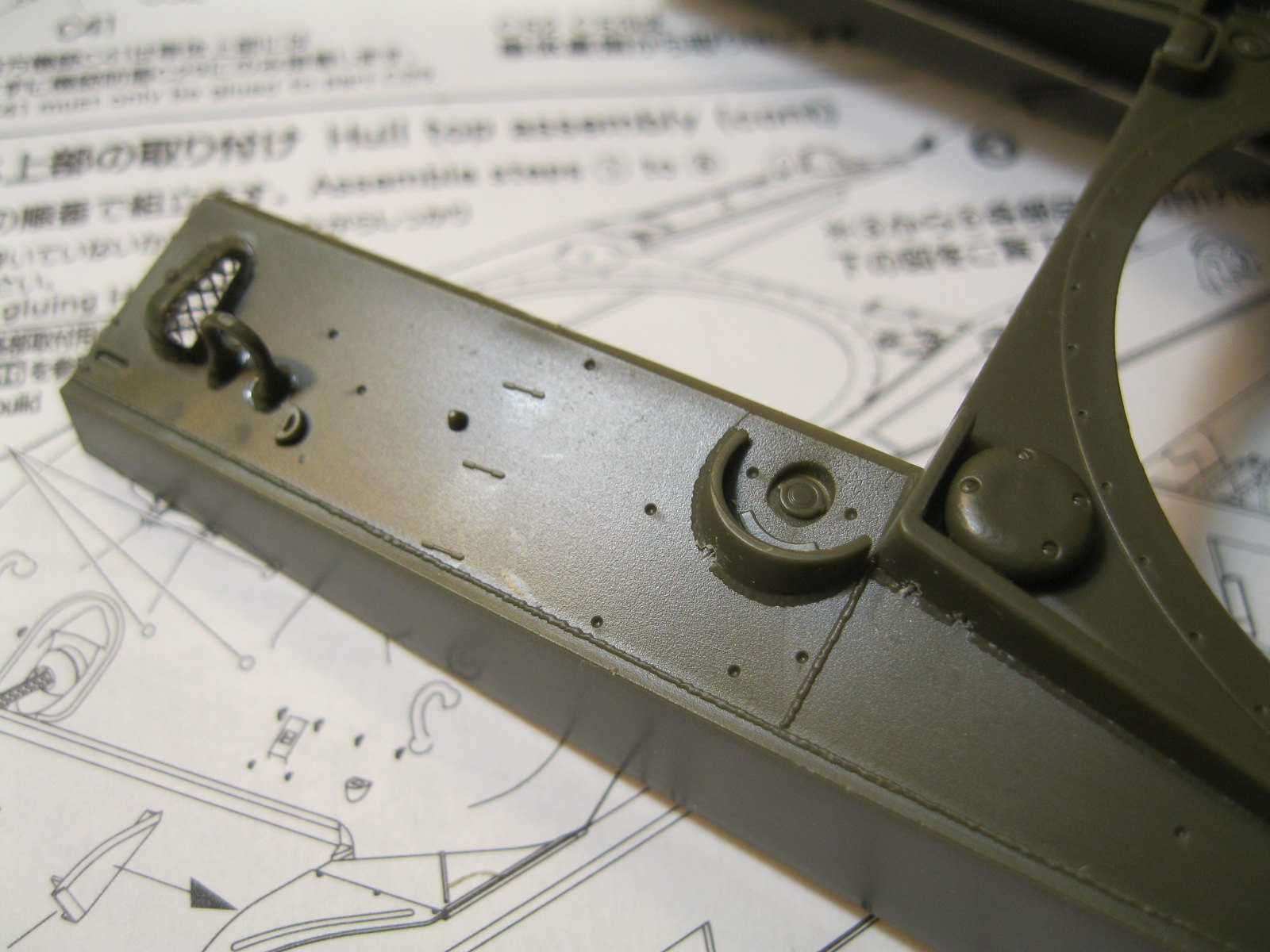
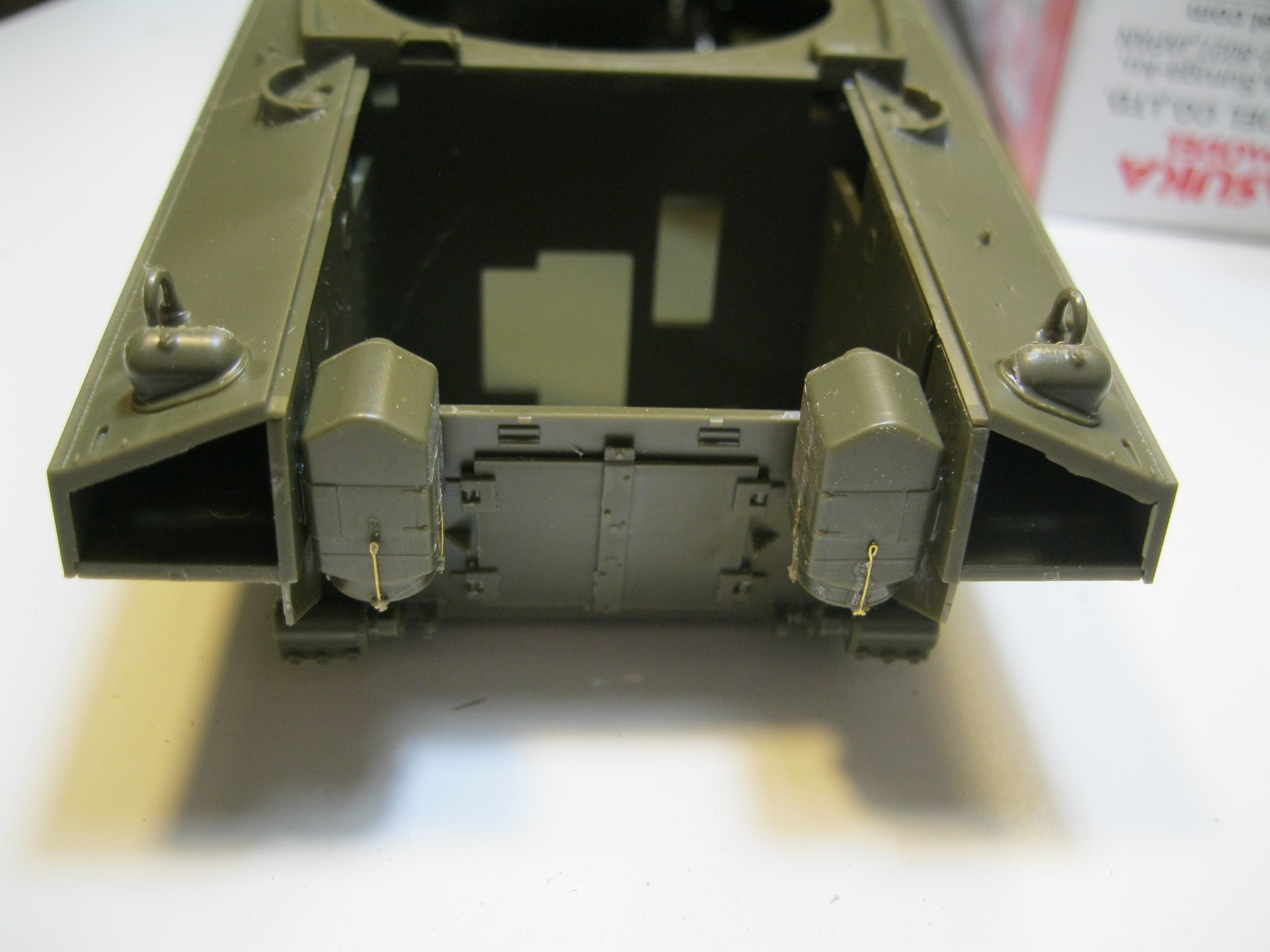
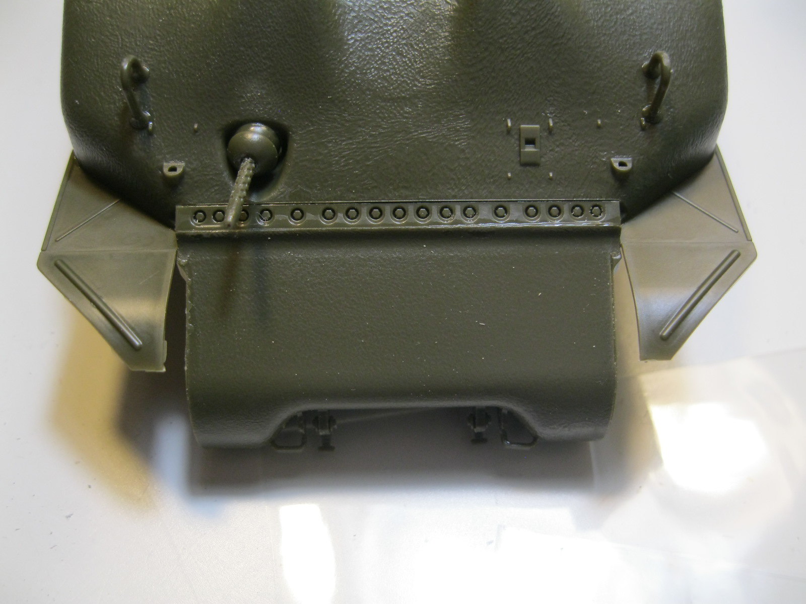
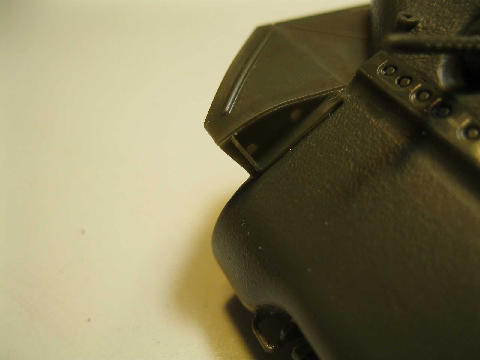
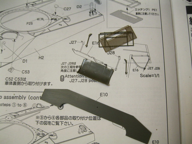
The grouser covers also get small etch screens. This is called out before the upper hull is shown but it will go right on, along with other small parts, so it is just a preparatory step. The hull is nicely done, with good casting texture on the front, a horizontal top edge where the side plates meet the engine deck and nice weld seam detail. There are small gaps in the weld bead around the turret and fuel cap splash guards for drain holes that you can add on your own. In comparing with the Dragon composite hull the only differences I can see are that the Dragon kit has softer contours around the hatches and includes the small bump on the glacis and the drain hole for the ventilator between the hatches. The foundry marks on the Tasca hull are facing opposite the Dragon marks. The Tasca kit includes a full, moveable hull MG, which I was happy to see just because it is there. German armor kits always have a highly detailed gun, even with no other interior. Allied kits usually just have a gun barrel that glues to the outside.
 IMG_9666
 by
russell amott, on Flickr
 IMG_9667
 by
russell amott, on Flickr
 IMG_9668
 by
russell amott, on Flickr
 IMG_9669
 by
russell amott, on Flickr
 IMG_9670
 by
russell amott, on Flickr
 IMG_9671
 by
russell amott, on Flickr
 IMG_9672
 by
russell amott, on Flickr
 IMG_9673
 by
russell amott, on Flickr
 IMG_9674
 by
russell amott, on Flickr
 IMG_9675
 by
russell amott, on Flickr
 IMG_9677
 by
russell amott, on Flickr
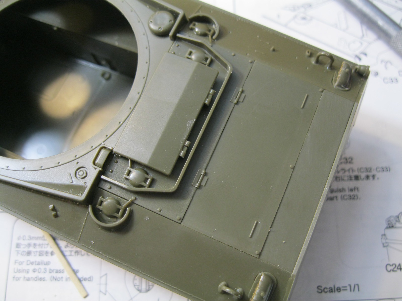
At this point the upper and lower hull sections can be joined. For me it was easier to start with the differential housing and then place the upper hull. Test fitting showed a couple of areas that needed some careful filing to get a nice fit, and then everything was glued, working around the edges slowly. Of note, the instructions say to drill three holes in the glacis to place the brackets for the barrel lock. The travel lock isn't present in the photo of China Clipper, but the locking clip is and I suspect the foot mounts are under the stowage.
 IMG_9680
 by
russell amott, on Flickr
 IMG_9681
 by
russell amott, on Flickr
 IMG_9682
 by
russell amott, on Flickr
 IMG_9683
 by
russell amott, on Flickr
 IMG_9684
 by
russell amott, on Flickr
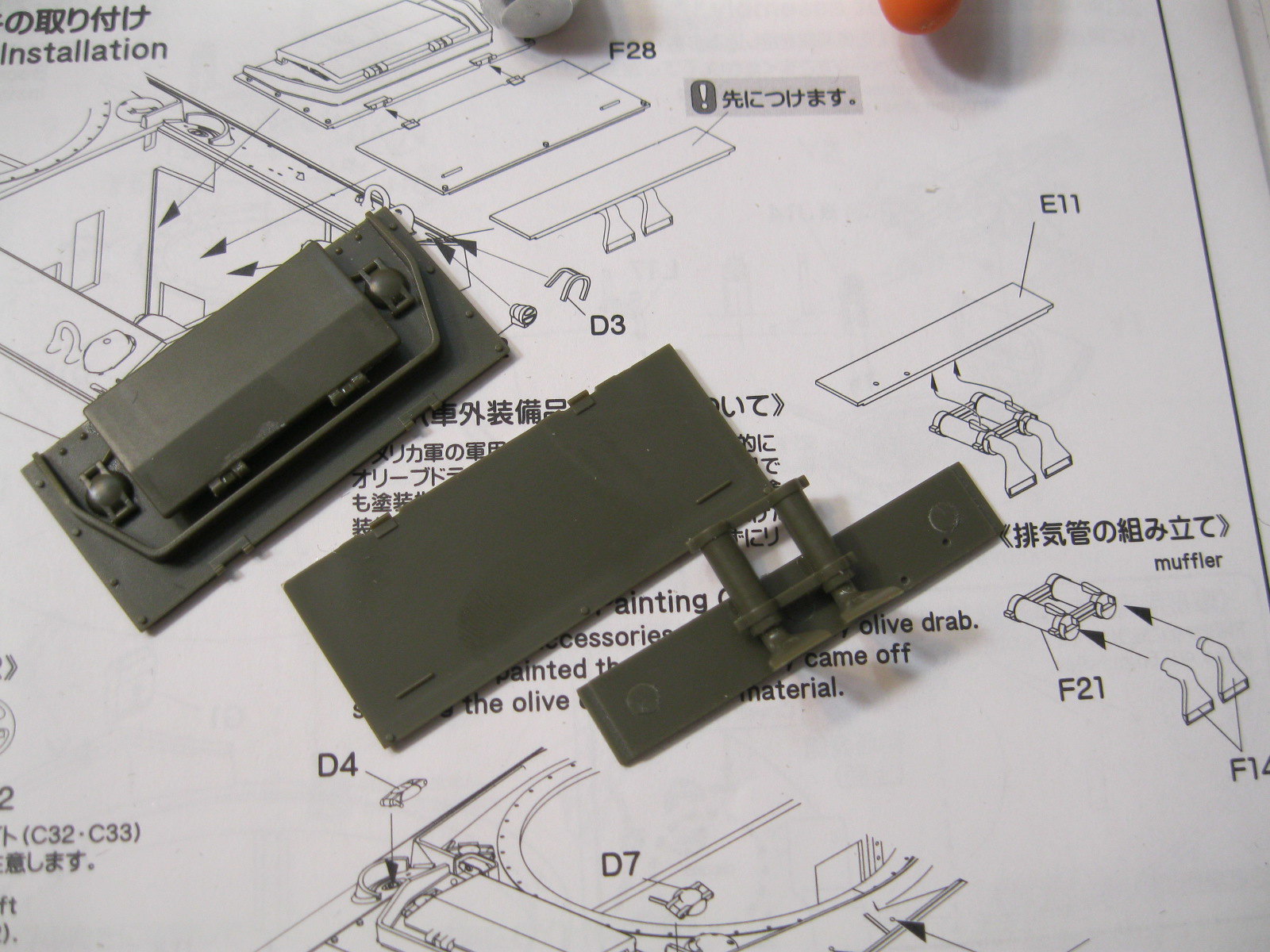
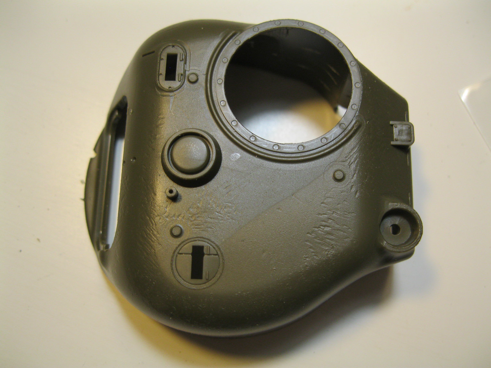
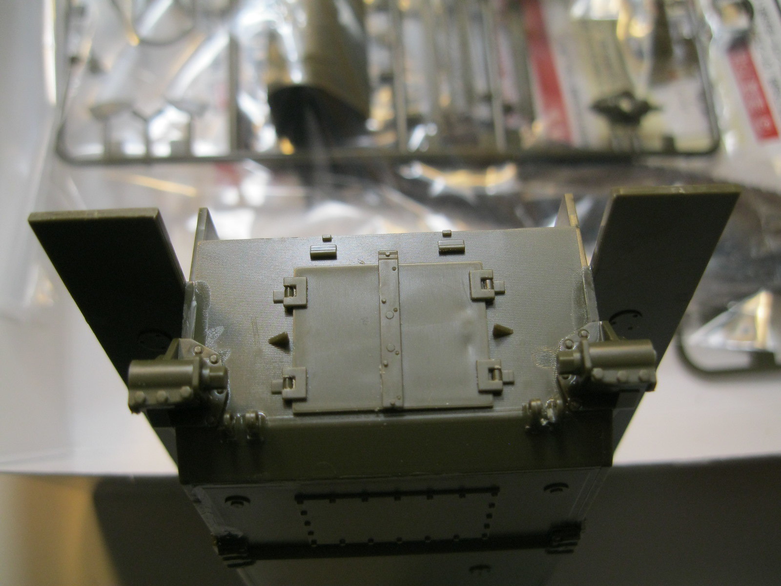
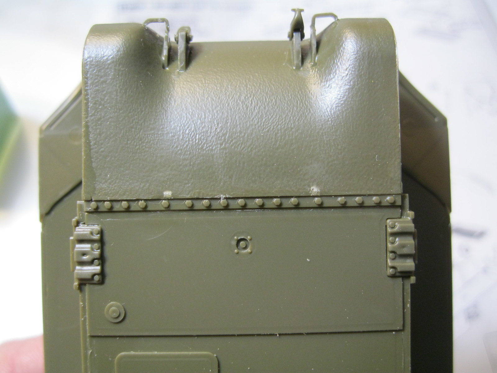
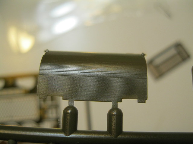
Next up is the exhaust deflector and rear plate. These parts also have the finely lined surface. I pulled out some steel wool and went over the parts carefully. The deflector is textured this way on the back surface. The front has three ejector pin marks that I worked to smooth out. The middle one received a dab of filler and was then smoothed. The etch screen rests on a plastic frame that has tiny attachment points. I placed the rear plate and then added these small details.
 IMG_9678
 by
russell amott, on Flickr
 IMG_9679
 by
russell amott, on Flickr
 IMG_9685
 by
russell amott, on Flickr
 IMG_9690
 by
russell amott, on Flickr
 IMG_9691
 by
russell amott, on Flickr
I was just about to start on the hull hatches but was given a gentle reminder to take a break and play with someone.
 IMG_9692
 by
russell amott, on Flickr
 IMG_9695
 by
russell amott, on Flickr
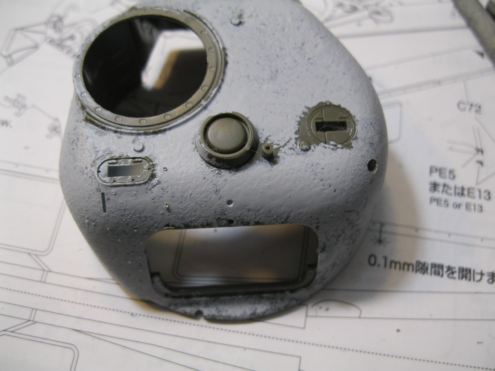
That is all for now. After playtime I will get back to the hatches. I also did some texturing on the turret to give it time to set. Still lots of things to do but life has priorities.


 China Clipper by russell amott, on Flickr
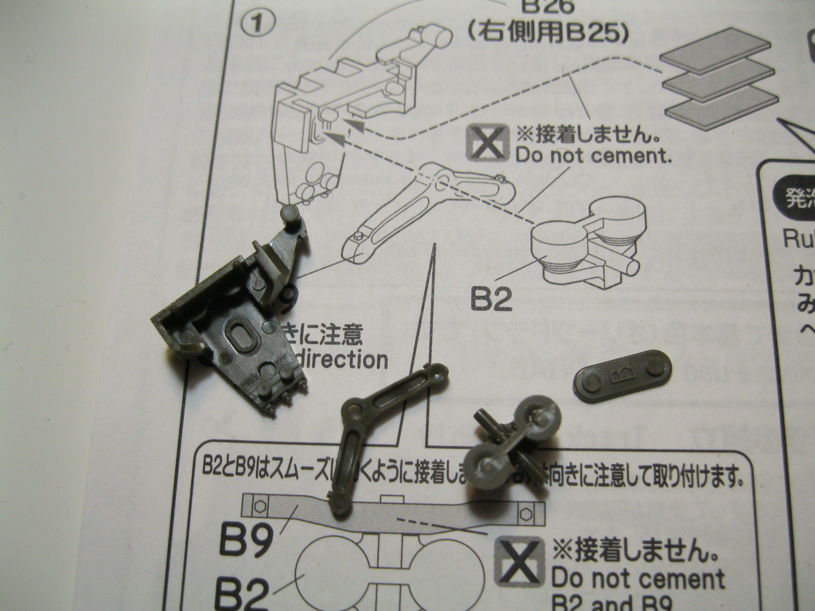
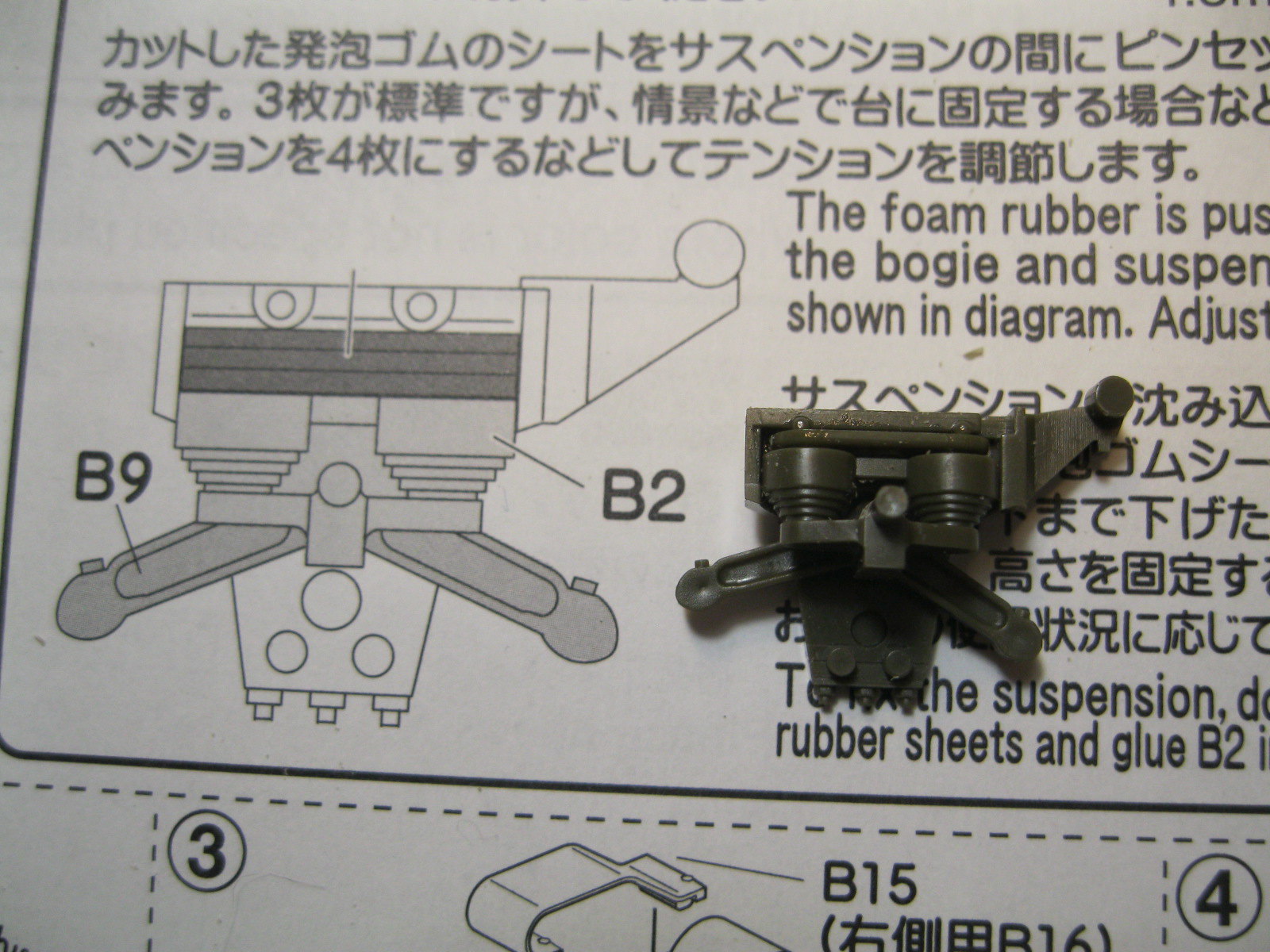
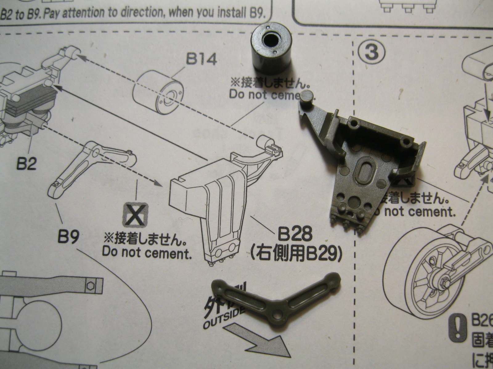
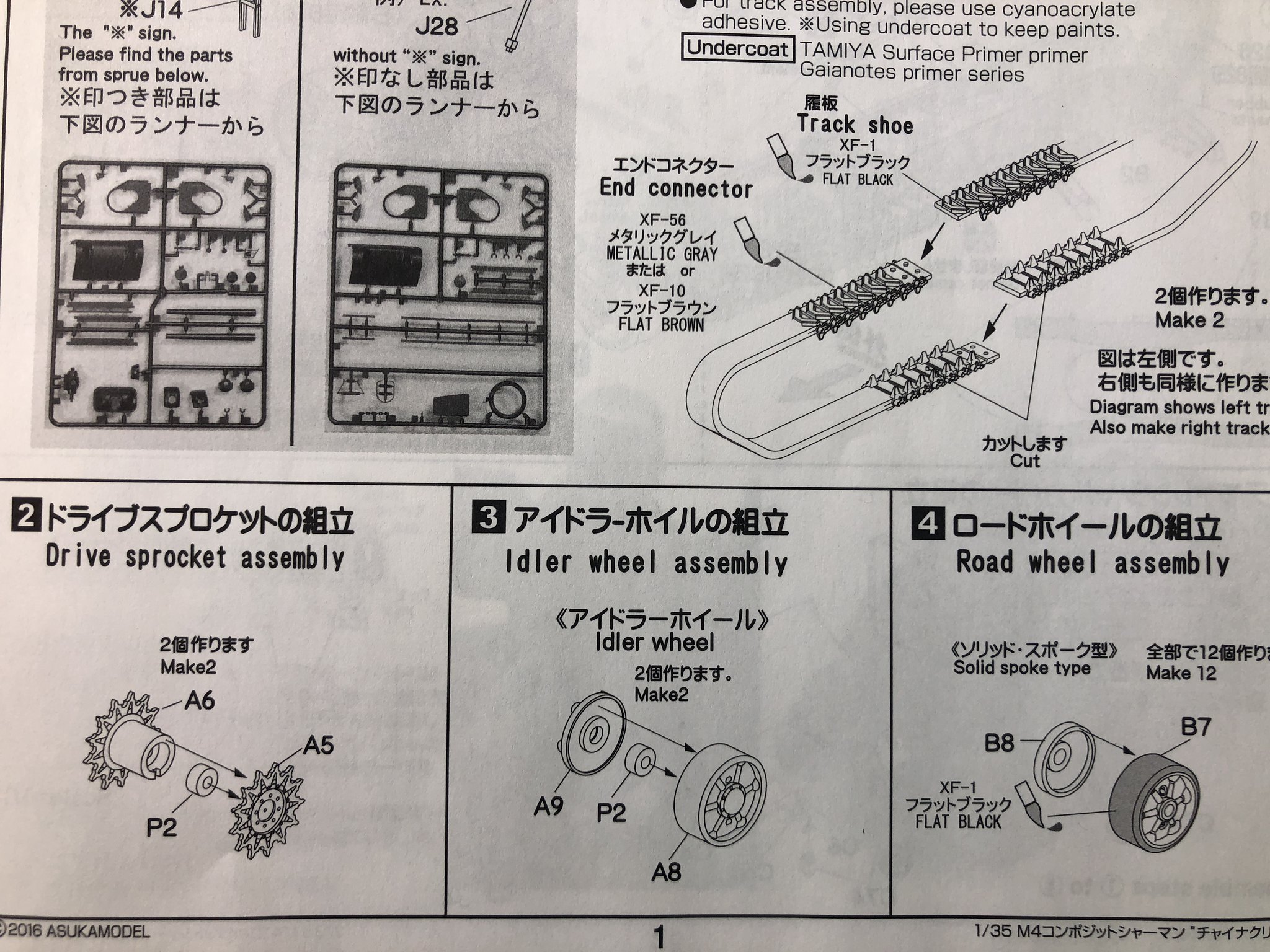 China clipper step 1 by russell amott, on Flickr
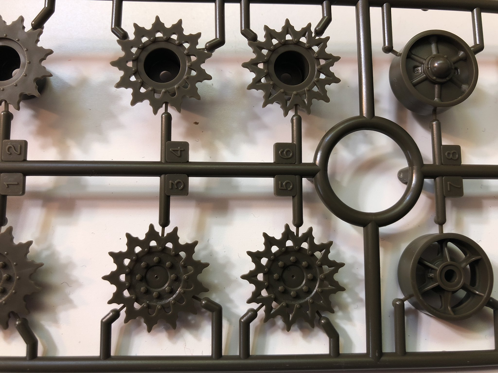 China Clipper fancy drive sprocket by russell amott, on Flickr
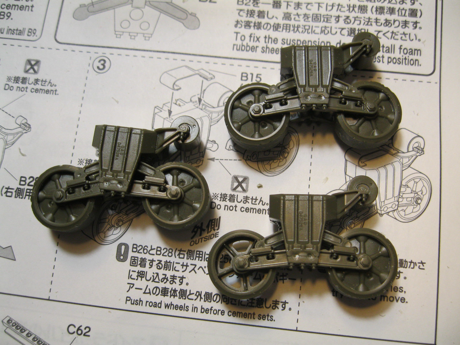
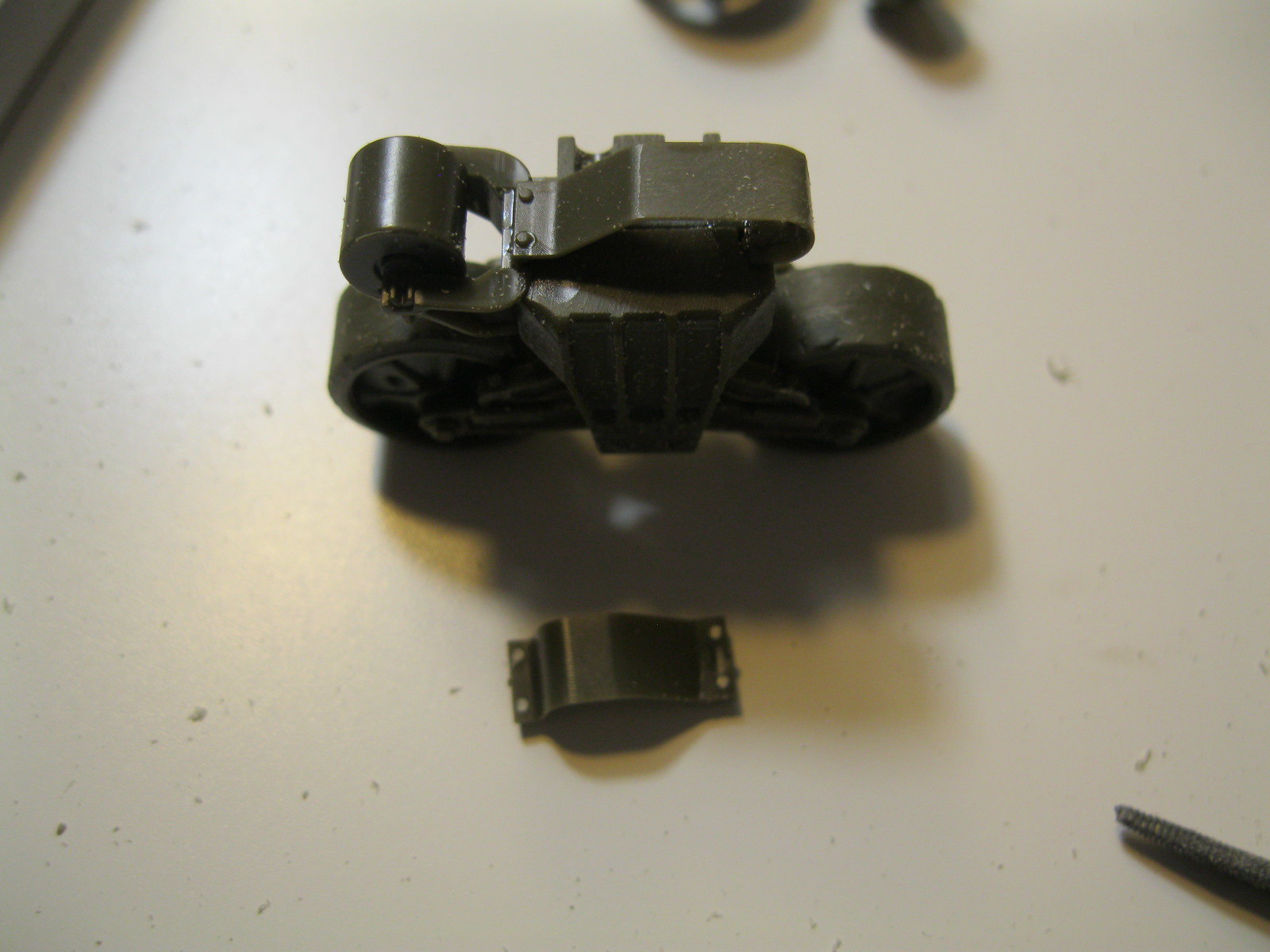
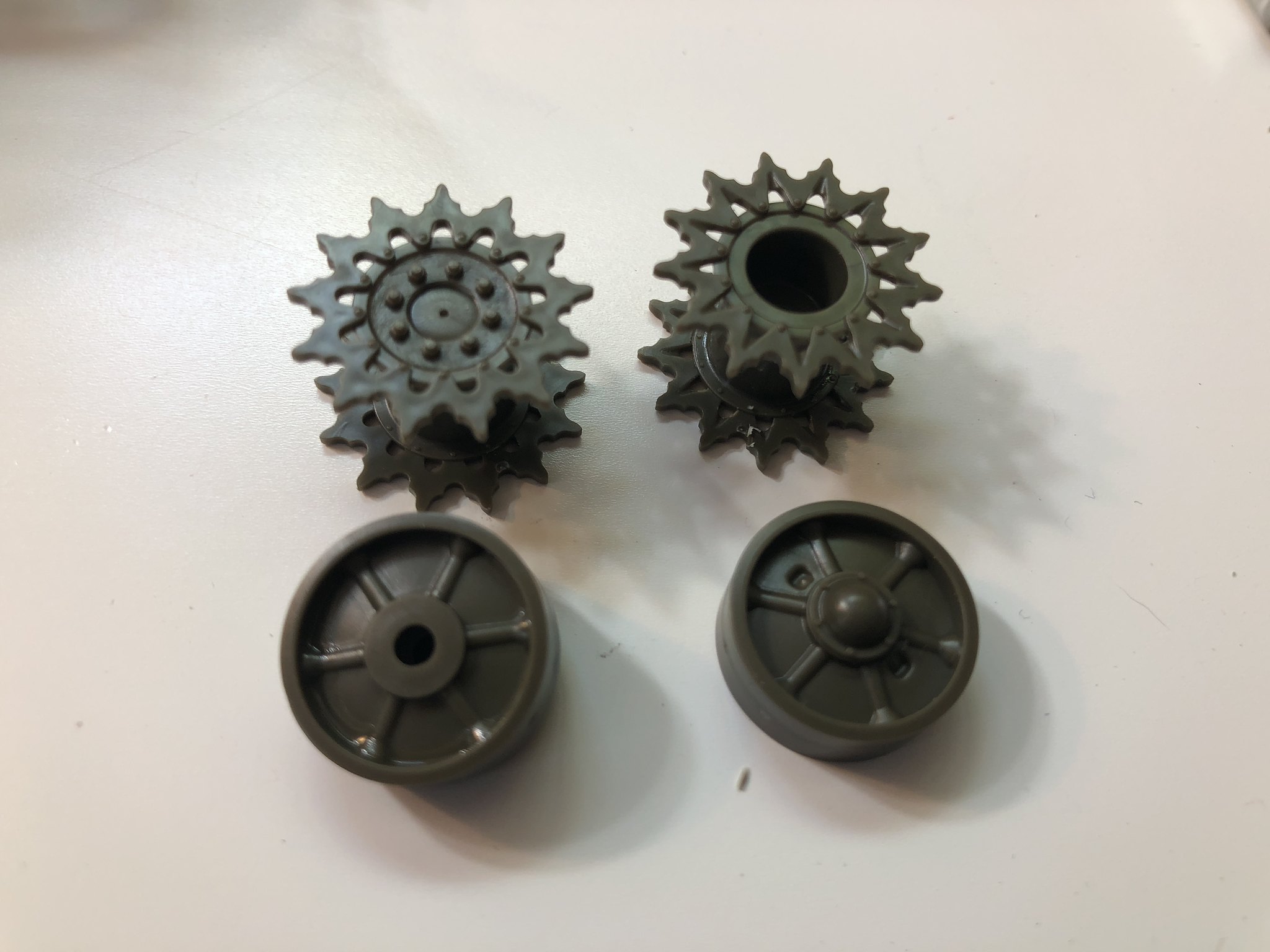 China clipper drive and idler by russell amott, on Flickr