M-59 155 mm LONG TOM - something went wrong
Krakow, Poland
Joined: November 23, 2018
KitMaker: 6 posts
Armorama: 6 posts
Posted: Friday, November 23, 2018 - 11:49 AM UTC
Hi there,
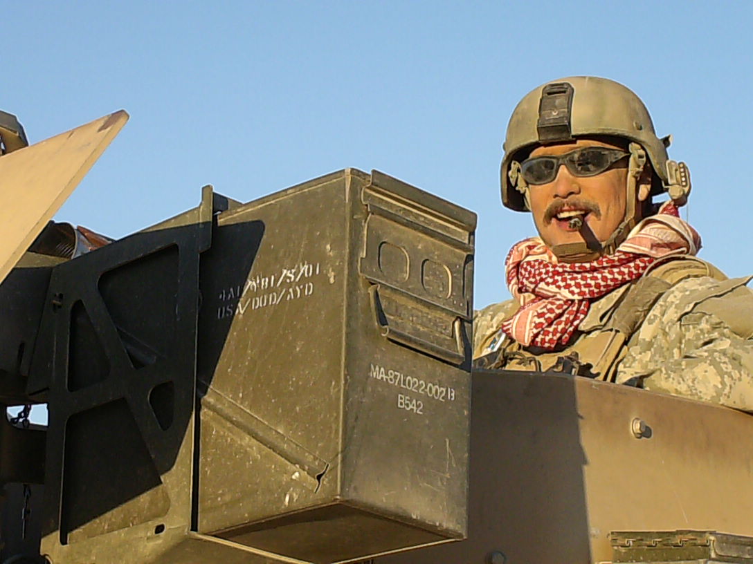
I'm in the middle of building this great kit from AFV. I've just finished the front carriage when I noticed that something isn't right here. Just have a look at the first axis of the back carriage.
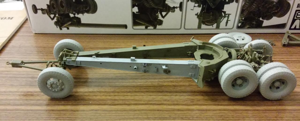
Now, I'm wondering where (or if) I've done this error. Any ideas how to fix that?
Colorado, United States
Joined: January 20, 2005
KitMaker: 7,219 posts
Armorama: 6,097 posts
Posted: Friday, November 23, 2018 - 12:10 PM UTC
That's something that really requires a closer examination on your part. But if I had to hazard a guess, it looks what something that happens in Texas on a daily basis - repositioning the axles underneath the leaf springs to give you that added lift.
A strong man stands up for himself; A stronger man stands up for others.
Admit nothing. Deny everything. Make counter-accusations.
He is not Khan who calls himself Khan. Afghan proverb
Pennsylvania, United States
Joined: January 18, 2003
KitMaker: 2,402 posts
Armorama: 2,377 posts
Posted: Friday, November 23, 2018 - 01:23 PM UTC
Quoted Text
Hi there,
I'm in the middle of building this great kit from AFV. I've just finished the front carriage when I noticed that something isn't right here. Just have a look at the first axis of the back carriage.
Now, I'm wondering where (or if) I've done this error. Any ideas how to fix that?
My guess is that you built the carriage without the limber under the end of the trails, so the wheels aligned to the carriage sitting with the trail ends on the table.
You will need to find what has bee attached that keeps the double axles from pivoting on the carriage so that the wheels stay on the table.
KL
North Carolina, United States
Joined: March 06, 2004
KitMaker: 1,171 posts
Armorama: 541 posts
Posted: Saturday, November 24, 2018 - 08:15 AM UTC
I ran into this same problem a dozen or so years ago. It's not your fault, the kit is not designed to be displayed with the limber in place, simple as that. If you leave off the limber the trails and bogies all sit nicely on the ground.
Luckily I discovered this early on in a test fit and took about half of it out by "cracking" (brute force with the mild sound of cracking glue & plastic) the bogey/carriage join and then took the remaining gap with some fishing line around that offending axle, right next to the wheel where it cannot be seen, and run through the base and tied tightly.
There are separate, but unrelated, problems with the limber. Unfortunately I cannot locate either my article on the build or the photos which might help illustrate all this. I suspect I built it online, maybe even here, and lost track of it. I am annoyed.
John Ratzenberger
It's my model and I'll do what I want with it.
All problems are soluble in stout.
Queensland, Australia
Joined: August 06, 2005
KitMaker: 3,353 posts
Armorama: 3,121 posts
Posted: Saturday, November 24, 2018 - 08:35 AM UTC
Hi Robert.
I think Kurt is partially right. You followed the build sequence and assembled the carriage wheel section as a separate unit... separate from the trails and all.... But probably glued the spring Parts B32 to the frame parts B31, making sure everything frame wise was vertical and the leaf springs horizontal. Correct?
When the dolly wheels are attached to the trail, it shifts the chassis Frame from vertical to slanting toward the front and the axles and leaf springs swivel accordingly, which is why the instructions say not to glue them. So your nicely secured carriage does not angle like it should with the dolly wheels attached.
Probably not going to be easy to fix, but you need to twist the leaf spring parts from the horizontal without breaking the securing pins. Good luck. Fingers crossed for you.
On the Bench:
Dust, styrene scraps, paint splotches and tears.
Rhone, France
Joined: December 02, 2002
KitMaker: 12,719 posts
Armorama: 12,507 posts
Posted: Saturday, November 24, 2018 - 08:55 AM UTC
Plan B :
Put it on a uneven ground....


H.P.
"Find the Bastards, then Pile On"
Col. George W.Patton III 's standing order for the troopers of the 11th Armoured Cavalry Regiment
Krakow, Poland
Joined: November 23, 2018
KitMaker: 6 posts
Armorama: 6 posts
Posted: Saturday, November 24, 2018 - 10:37 AM UTC
So I have 2 options:
1) Try do fix it (risky)
2) Make a small diorama (I want to build M4 HST as well)
Krakow, Poland
Joined: November 23, 2018
KitMaker: 6 posts
Armorama: 6 posts
Posted: Monday, November 26, 2018 - 12:14 AM UTC
I think this can be fixed in the following way:
So I'll have to bend the leaf spring on booth sides. This will be hard to notice once the whole veihicile is finished.

#521
Kentucky, United States
Joined: April 13, 2011
KitMaker: 9,465 posts
Armorama: 8,695 posts
Posted: Monday, November 26, 2018 - 01:40 AM UTC
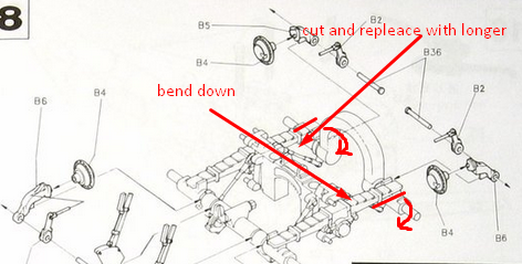
If I use the expression "travel limit cables" referring to the above photo might you recognize the four parts I am talking about?
Assuming you did not glue the entire spring rocker/axle assembly permanently to the the gun chassis, snipping these four "cables" will allow the entire wheel/axle assembly to rock (as it should) relative to the main gun chassis.
Please excuse the poor quality of my drawing. (To para-phrase Professor Brown in "Back To The Future".)
Robert you are correct that AFV designed this model to be posed in firing position. The darkened part in the drawing is the limit cable. In real life this cable is much longer and would be flexed (not straight) when the gun assembly is "on limber" being towed. ** If you cut all four lower mounting points where I have indicated the wheel assembly will be freed and now rock as you had hoped. It would probably be a good idea after cutting to sand both the cable end and the axle to keep these two parts from catching on each other. You might wish to bend the cable downward just slightly to better clear the axle. This somewhat crude alteration should be unnoticeable accept with the closest of inspections. Also these now slightly bent cables will actually appear more true to life than AFV's ramrod straight cables.
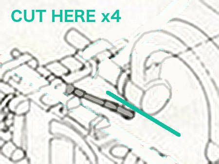
** AFV really should have made these 4 parts out of two molded cable ends and a short piece of string just like a tiny tank tow cable. If done this way the cables could have then flexed the way the gun chassis designers originally intended.
#521
Kentucky, United States
Joined: April 13, 2011
KitMaker: 9,465 posts
Armorama: 8,695 posts
Posted: Monday, November 26, 2018 - 02:42 AM UTC
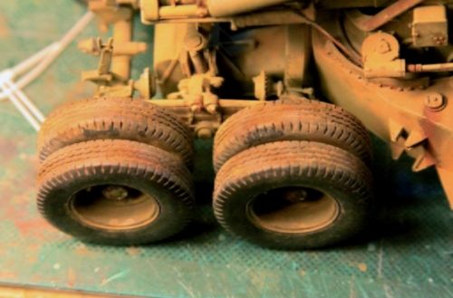
Might I ask who's back dated civilian pattern tires you are using on you gun? Is there a new source for these? I got mine from Scale-Link in England but I am not sure they are still available.
#521
Kentucky, United States
Joined: April 13, 2011
KitMaker: 9,465 posts
Armorama: 8,695 posts
Posted: Monday, November 26, 2018 - 02:52 AM UTC
My original solution was not as elegant. Upon discovering the problem I left the cable ends but cut away the entire length of the cable itself. Still few would ever notice the modification.
Krakow, Poland
Joined: November 23, 2018
KitMaker: 6 posts
Armorama: 6 posts
Posted: Monday, November 26, 2018 - 02:54 AM UTC
Quoted Text
Might I ask who's back dated civilian pattern tires you are using on you gun? Is there a new source for these? I got mine from Scale-Link in England but I am not sure they are still available.
I bought these here ->
https://www.dersockelshop.de/conversion-sets/1-35-conversions/long-tom-wheels.-type-2-afv-club-1-35_hussar-productions_hsr35115.htmlNow, I like the concept of cutting these "wires". But ther's another problem:
#521
Kentucky, United States
Joined: April 13, 2011
KitMaker: 9,465 posts
Armorama: 8,695 posts
Posted: Monday, November 26, 2018 - 02:58 AM UTC
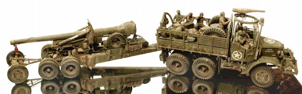
I am not going to reveal any details accept to say, sometime in the not too distant future there may be something other than a High Speed Tractor to pull those 155mm and 8 inch guns!
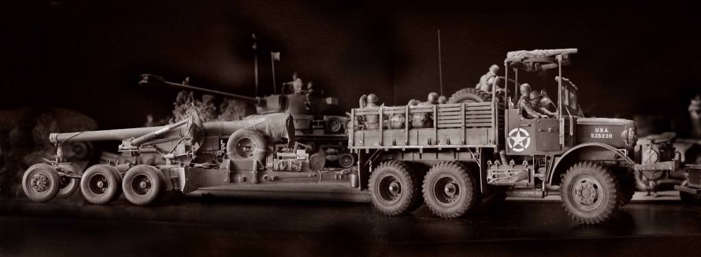
This photo is of my scratch built Mack NO from some years ago but a model of the Mack IN PLASTIC may finally be coming in the near future!
#521
Kentucky, United States
Joined: April 13, 2011
KitMaker: 9,465 posts
Armorama: 8,695 posts
Posted: Monday, November 26, 2018 - 03:06 AM UTC
Quoted Text
Now, I like the concept of cutting these "wires". But ther's another problem:
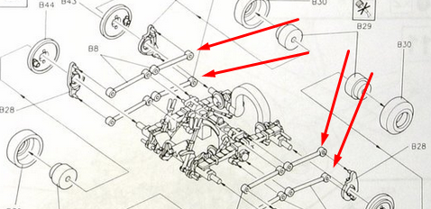
Ah yes, the problem DOES go further than than that doesn't it?
Sorry, my bad, I was working from memory rather than going back and actually consulting the model.
On those 8 torque rods** where they attach to that center mount - simply DON'T - Don't glue them! Glue them only at their outboard ends. Sand their attachment pins off and allow them to slide horizontally over that center mounting plate as the wheel/axle assembly rocks. Mine in the photo above are not attached in the center yet they appear to be. If you have already glued them it should be possible to slide a thin jewelers saw in behind them and cut them free. I assure you my entire wheel assembly rocks on the chassis just as it does on the real gun with these modifications.
Just to verify one other thing. These changes must not be easily seen as this gun has won awards in the towed artillery class. - Not bragging - Just say'n the judges didn't notice my changes.
** Torque rods, radius rods - whatever we want to call them!
RobinNilsson
 TOS Moderator
Stockholm, Sweden
Joined: November 29, 2006
KitMaker: 6,693 posts
Armorama: 5,562 posts
Posted: Monday, November 26, 2018 - 03:09 AM UTC
Quoted Text
I am not going to reveal any details accept to say, sometime in the not too distant future there may be something other than a High Speed Tractor to pull those 155mm and 8 inch guns!
This photo is of my scratch built Mack NO from some years ago but a model of the Mack IN PLASTIC may finally be coming in the near future!
NO kidding??
In memory of Al Superczynski:
"Build what YOU want, the way YOU want to....
and the critics will flame you every time"
#521
Kentucky, United States
Joined: April 13, 2011
KitMaker: 9,465 posts
Armorama: 8,695 posts
Posted: Monday, November 26, 2018 - 03:22 AM UTC
It could happen!
Magic 8 Ball says: "Chances Are Good!"
#521
Kentucky, United States
Joined: April 13, 2011
KitMaker: 9,465 posts
Armorama: 8,695 posts
Posted: Monday, November 26, 2018 - 04:00 AM UTC
Quoted Text
Might I ask who's back dated civilian pattern tires you are using on you gun? Is there a new source for these? I got mine from Scale-Link in England but I am not sure they are still available.
Lov'n that website! Have not found the resin detail parts section yet but their selection of kits is amazing! WOW
Fyn, Denmark
Joined: April 16, 2007
KitMaker: 352 posts
Armorama: 342 posts
Posted: Monday, November 26, 2018 - 04:09 AM UTC
Quoted Text
I am not going to reveal any details accept to say, sometime in the not too distant future there may be something other than a High Speed Tractor to pull those 155mm and 8 inch guns!
.......
a model of the Mack IN PLASTIC may finally be coming in the near future!
Now that IS fantastic news!!
#521
Kentucky, United States
Joined: April 13, 2011
KitMaker: 9,465 posts
Armorama: 8,695 posts
Posted: Monday, November 26, 2018 - 04:39 AM UTC
Just had a thought but it is only a theory:
I wonder if we were to reverse the part order and put the longer limit cables indicated to go in the front, put them in the rear and those shorter ones in the rear and put them in the front. Then do the same thing with the 8 torque rods . . . I wonder if we wouldn't end up with a wheel set properly positioned on the chassis to work with the limber for towing??????
In actuality I suspect the trails would then be a bit too high to work properly with the M5 Limber but we would only know for sure if someone tries it.
RobinNilsson
TOS Moderator Stockholm, Sweden
Joined: November 29, 2006
KitMaker: 6,693 posts
Armorama: 5,562 posts
Posted: Monday, November 26, 2018 - 04:59 AM UTC
Quoted Text
Just had a thought but it is only a theory:
I wonder if we were to reverse the part order and put the longer limit cables indicated to go in the front, put them in the rear and those shorter one in the rear and put them in the front. Then do the same thing with the 8 torque rods . . . I wonder if we wouldn't end up with a wheel set properly positioned on the chassis to work with the limber for towing??????
In actuality I suspect the trails would then be a bit too high to work properly with the M5 Limber but we will only know for sure if someone tries it.
Are those rods telescopic in real life?
The part numbers in the assembly diagram seem to be the same and there doesn't seem to be anything to orient them front-rear.
My uninformed guess is that the rods have a constant length and just make sure that the wheel doesn't tilt (keeps part B28 upright as the wheel and springs move up and down).
I think the cause of the problem is those cables and gluing the "movable" parts solid to fit the cables.
I'll need to check my unbuilt Long Tom ...
/ Robin
In memory of Al Superczynski:
"Build what YOU want, the way YOU want to....
and the critics will flame you every time"
#521
Kentucky, United States
Joined: April 13, 2011
KitMaker: 9,465 posts
Armorama: 8,695 posts
Posted: Monday, November 26, 2018 - 05:49 AM UTC
You are correct the rods are supposed to be of equal length (are NOT telescopic) and serve to keep the wheel bearing and brake drum (and wheel) in a vertical orientation durning braking.
I had assumed that on the AFV model they were of different lengths. I guess it is just those limit cables that are of differing and incorrect lengths.
RobinNilsson
TOS Moderator Stockholm, Sweden
Joined: November 29, 2006
KitMaker: 6,693 posts
Armorama: 5,562 posts
Posted: Monday, November 26, 2018 - 06:23 AM UTC
Quoted Text
You are correct the rods are supposed to be of equal length (are NOT telescopic) and serve to keep the wheel bearing and brake drum (and wheel) in a vertical orientation durning braking.
I had assumed that on the AFV model they were of different lengths. I guess it is just those limit cables that are of differing and incorrect lengths.
Thanks! My guessing wasn't totally off ....
and those cables "force" the whole assembly into a specific tilt angle. If they had modelled them on a gun in firing position the cables could possibly have been shaped as if they had been flexing but they would have locked the bogie into a specific angle.
/ Robin
In memory of Al Superczynski:
"Build what YOU want, the way YOU want to....
and the critics will flame you every time"
Canada
Joined: November 07, 2011
KitMaker: 5 posts
Armorama: 4 posts
Posted: Monday, November 26, 2018 - 06:34 AM UTC
Inside rear axle was set in place without front trailer wheels up under trailing arms. It would have been alright if gun was in firing order.
#521
Kentucky, United States
Joined: April 13, 2011
KitMaker: 9,465 posts
Armorama: 8,695 posts
Posted: Monday, November 26, 2018 - 06:46 AM UTC
Exactly.
As we said earlier - AFV molded them at that length which accommodates ONLY building the gun in firing position.
If AFV had built these "over travel limit cables' as real cables we would not be having this problem.
They should have offered them like little miniature tank tow cables with clevises glued at each end and a short length of flexible string in-between.
Rhone, France
Joined: December 02, 2002
KitMaker: 12,719 posts
Armorama: 12,507 posts
Posted: Monday, November 26, 2018 - 06:57 AM UTC
When the gun is in travelling mode, the "wheel-supporting cables" (kit parts B34 & B35) are hung on the torque rod hooks. Here's what must be done to ready the gun carriage for firing :

A TM picture should make things clearer

H.P.
"Find the Bastards, then Pile On"
Col. George W.Patton III 's standing order for the troopers of the 11th Armoured Cavalry Regiment