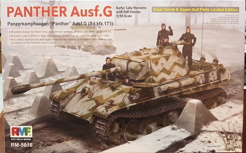
The Panther Ausf. G was the final production version in the Panther family. The Ausf. G incorporated a simplified chassis while retaining the Ausf. A running gear. The turret was the same as that used on the Panther Ausf. A. The Ausf. G began production at M.A.N. (the primary contractor) in March 1944. Daimler-Benz switched to Ausf. G production in May 1944; with M.N.H switching in early July 1944. All production vehicles, through September 1944, left the factory with zimmerit applied.
Whats in the Box
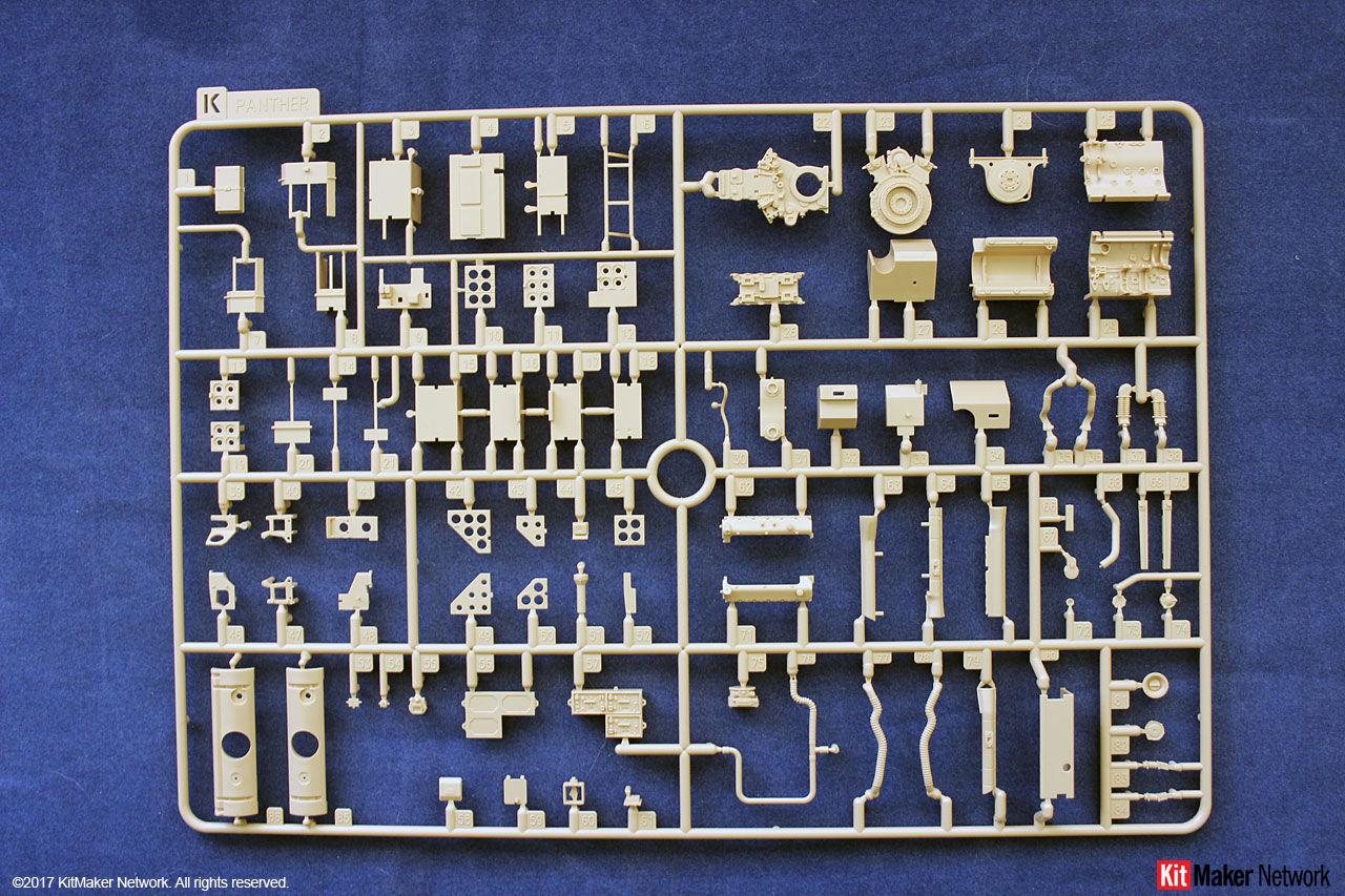
The kit is from Rye Field Model and released in 2018. This is a very large box, measuring 15in x 9.5in x 6in (38cm x 24cm x 15cm). Whats in the box:
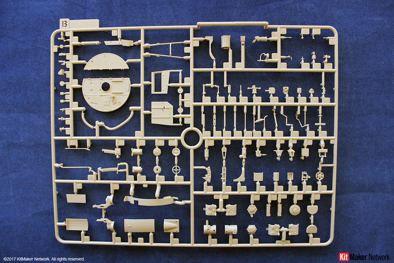
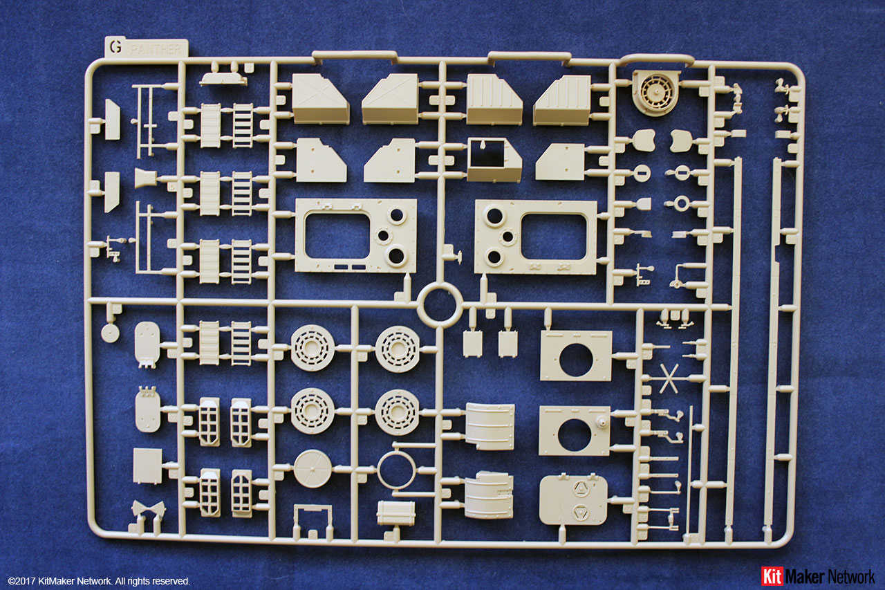
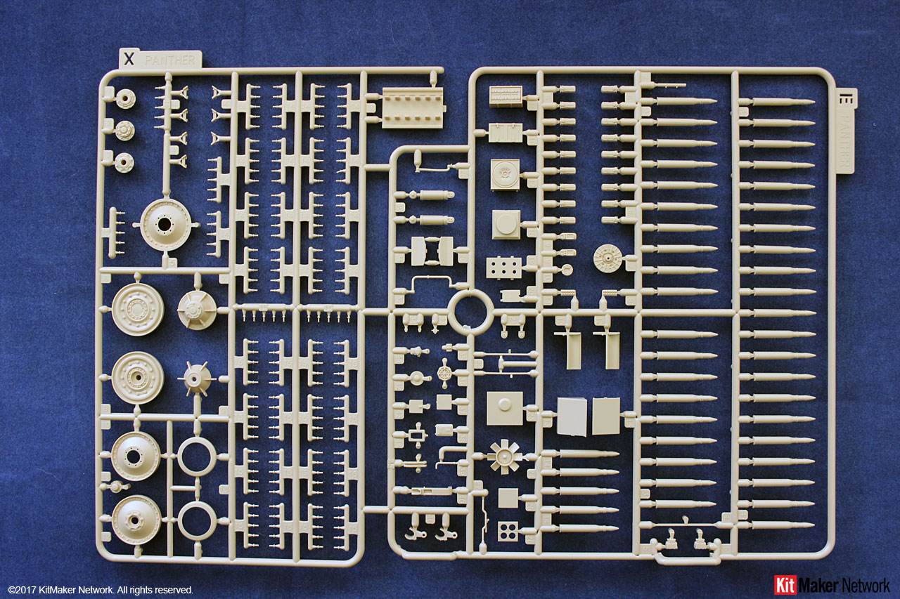
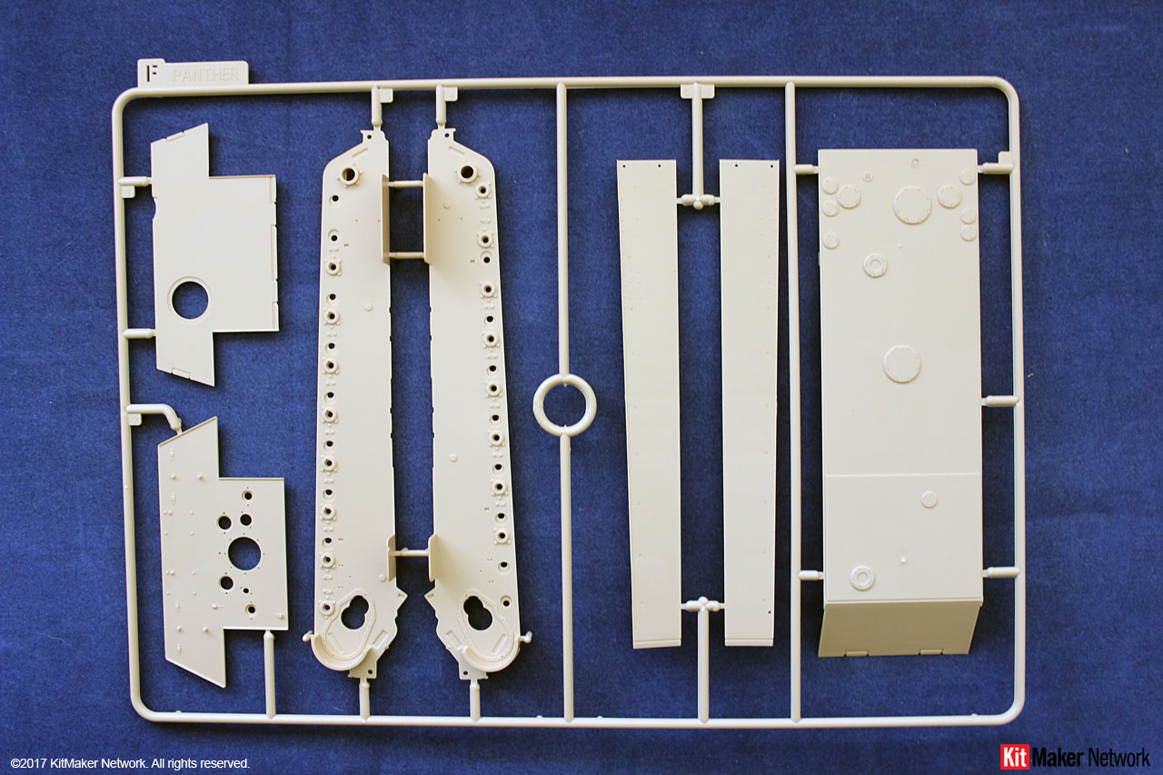
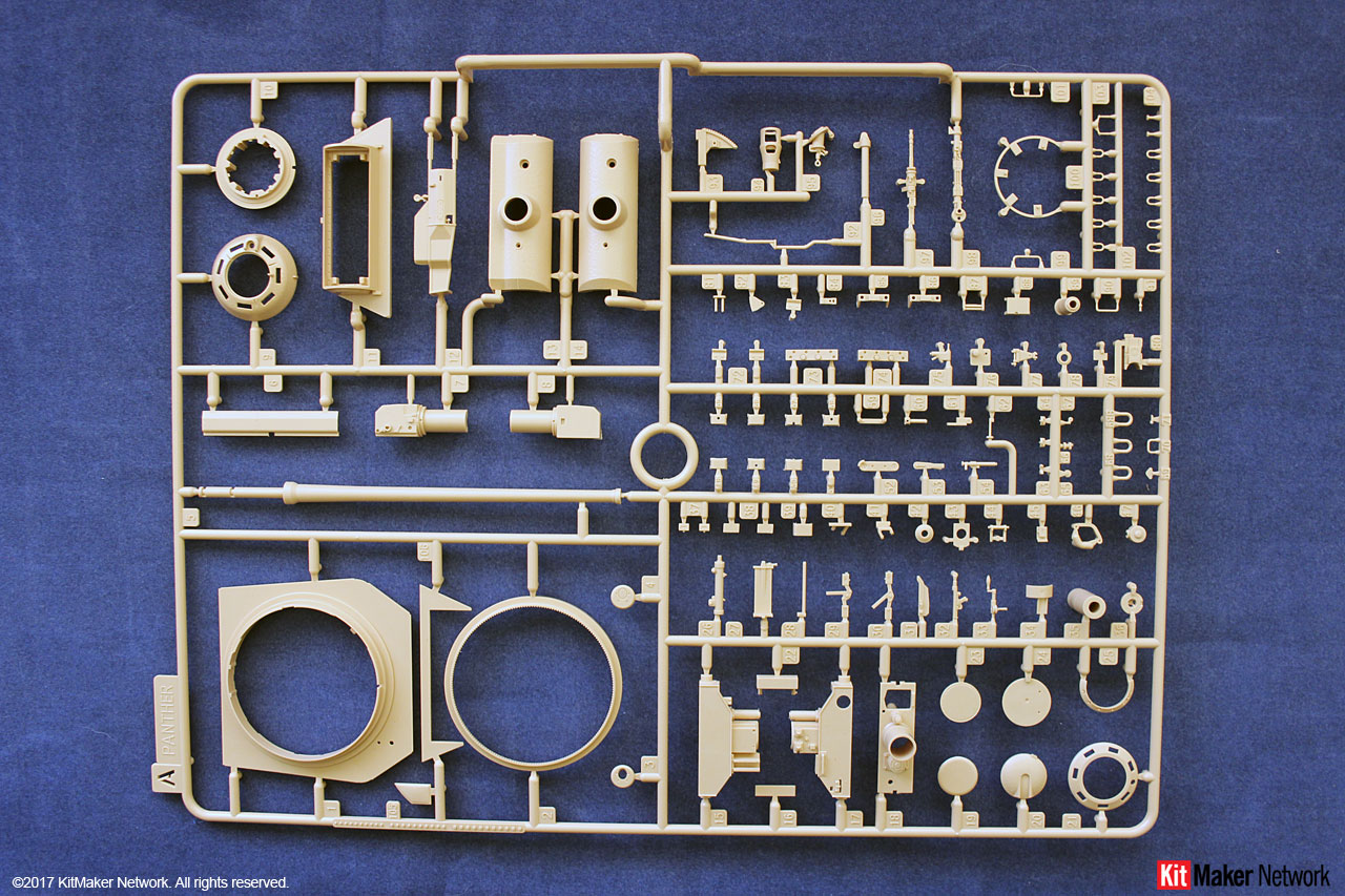
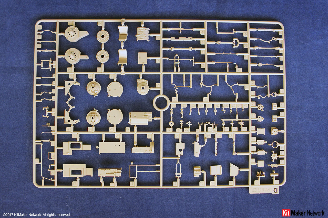
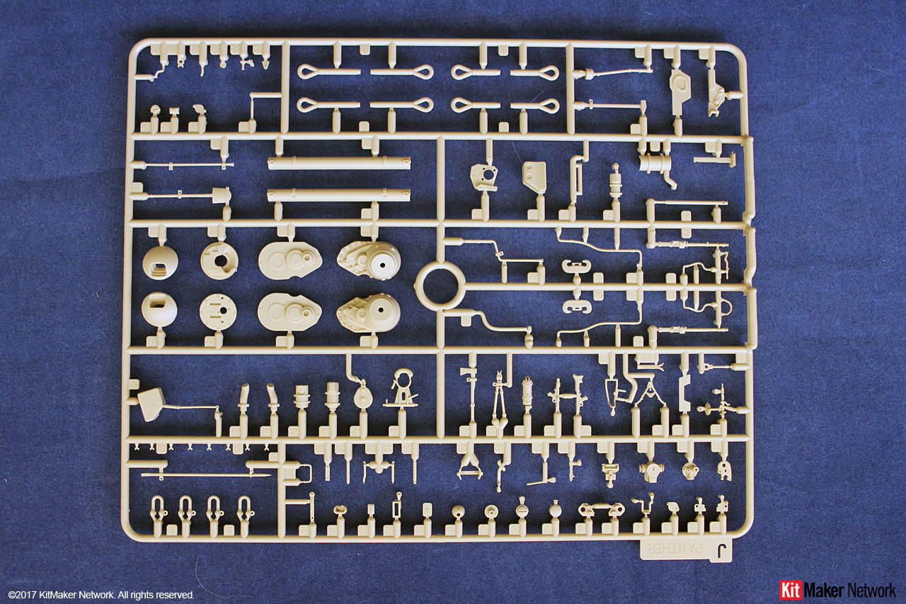
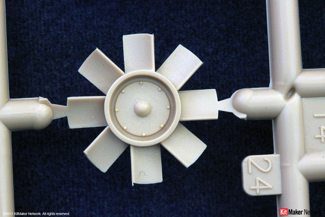
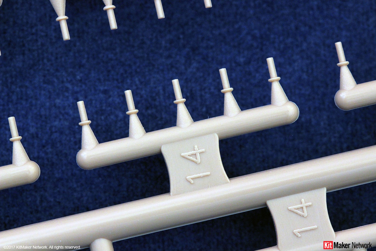
14 sprues molded in beige
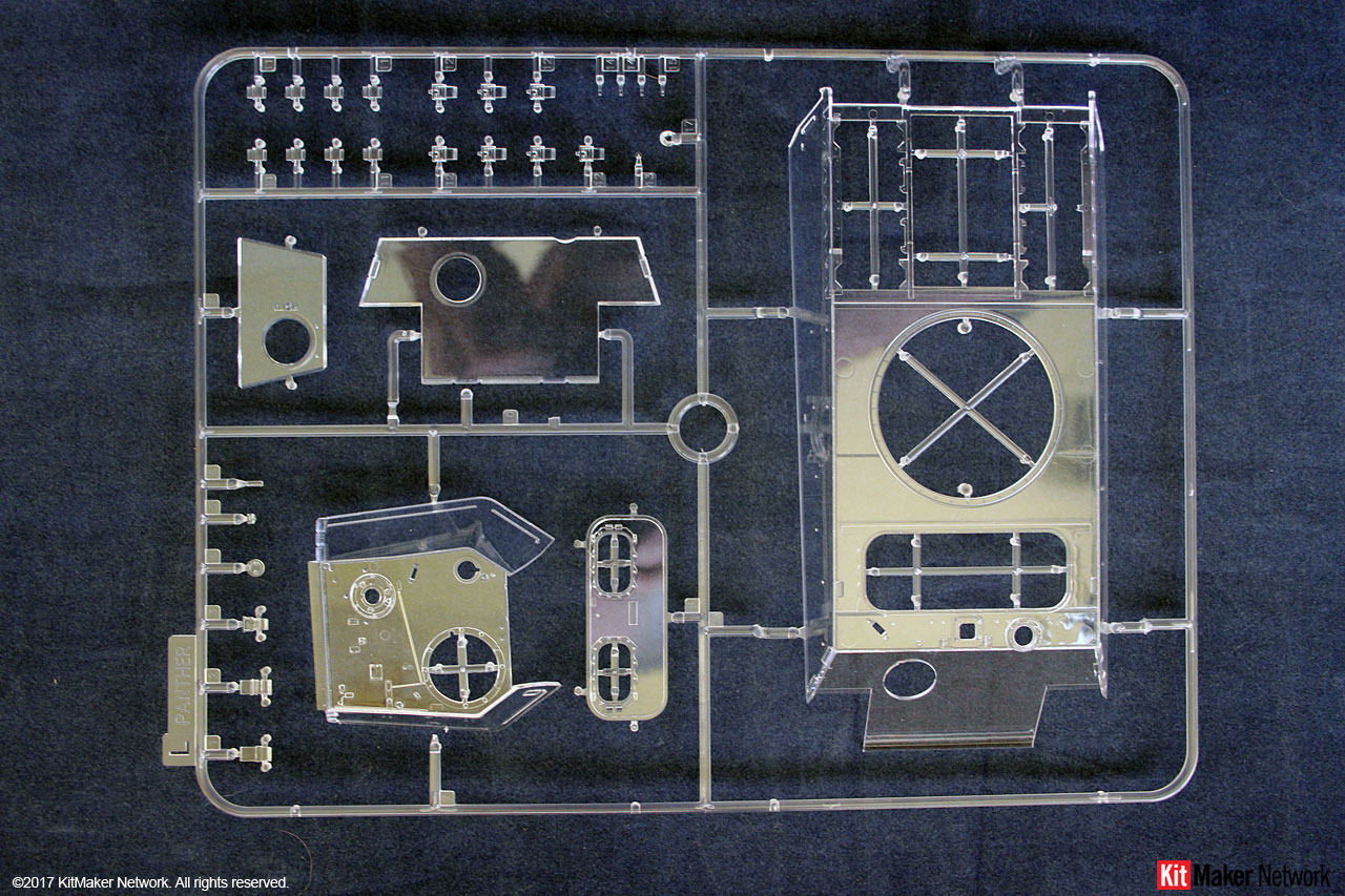
1 sprue molded in clear
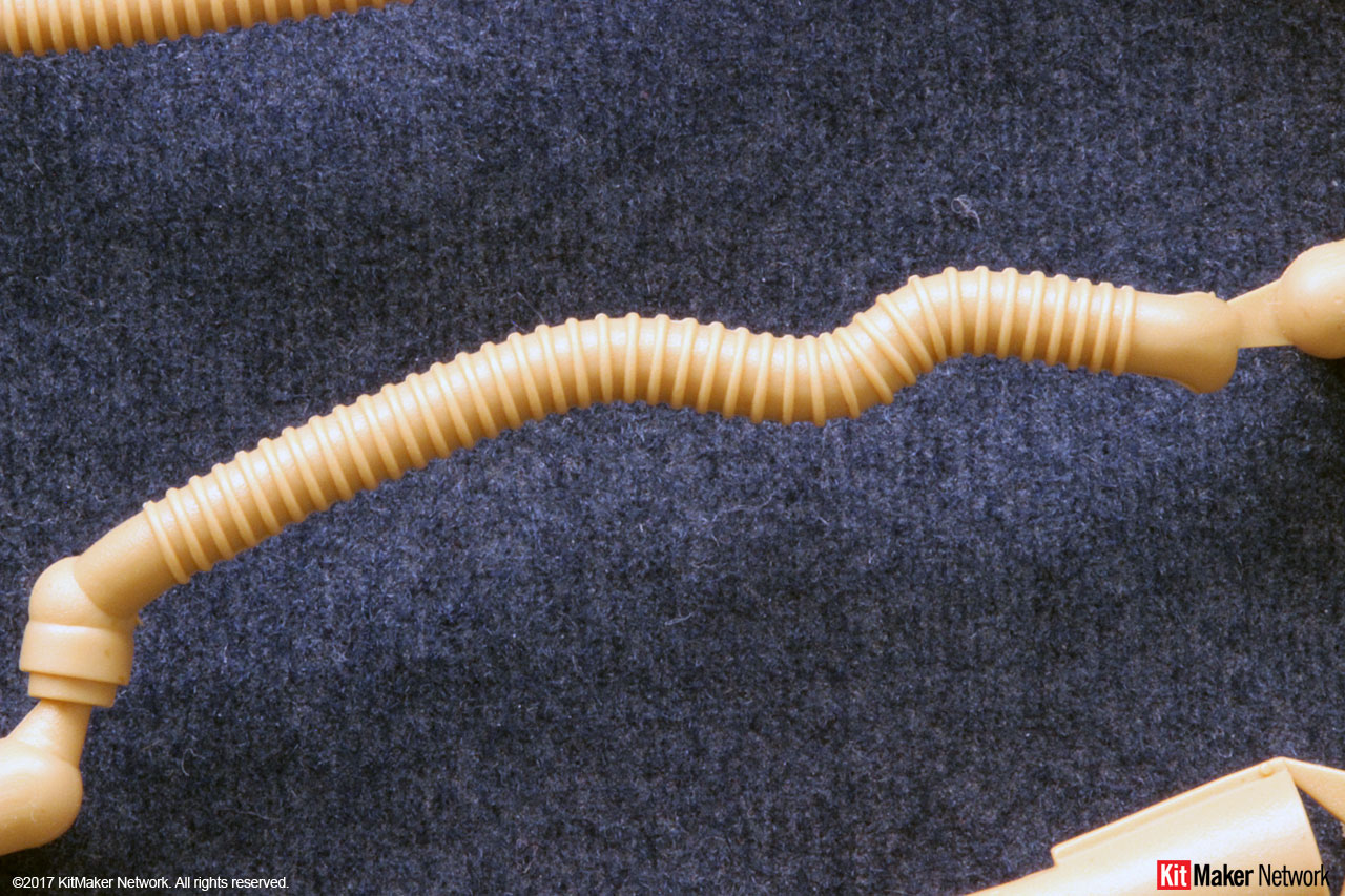
1 sprue rubber molded
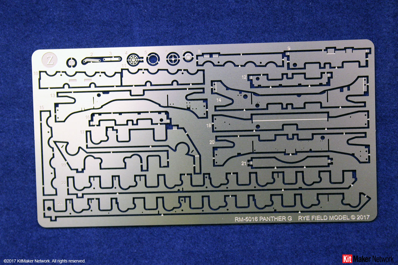
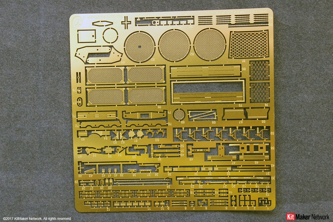
2 PE Frets
1 bag of track links
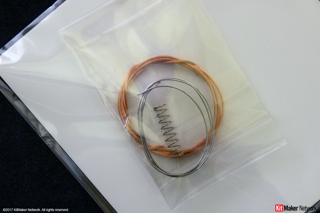
1 bag with 2 sizes of wire and a spring
1 decal sheet
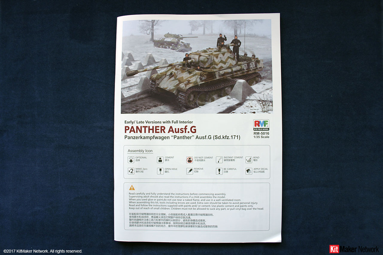
1 52 page Instruction manual
Jim has a video review of the kit posted in the forum. The video and images used here are those produced by Jim Starkweather.
Looking at the Kit
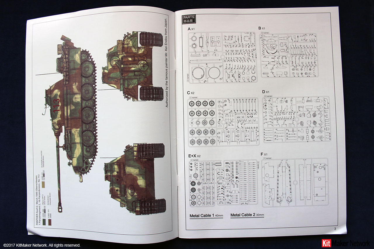
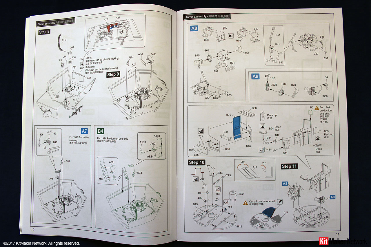
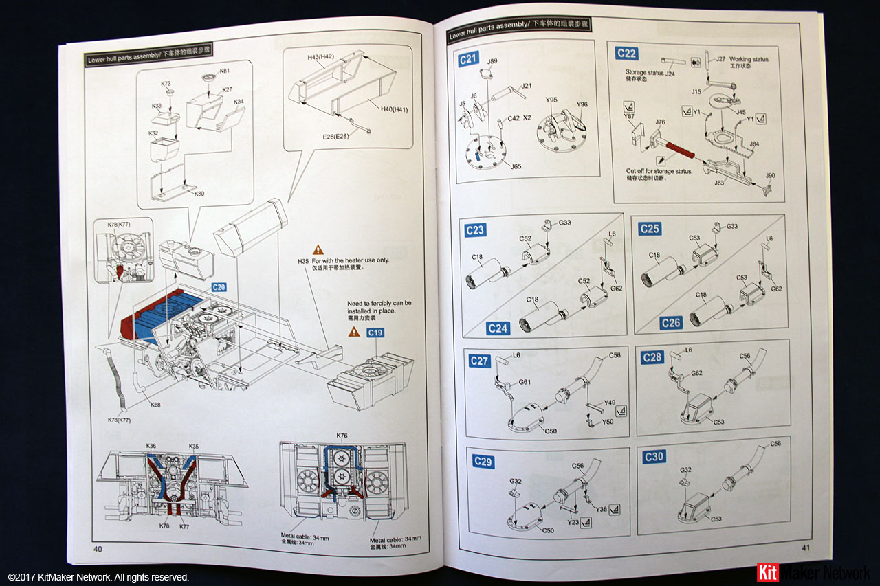
Instructions Standard RFM format consisting of 48 pages of line drawings. Assembly is broken down into 71 steps. In addition, there are numerous sub-assembly steps that bring the total assembly steps to more than 110. The blue A steps are primarily for the 1945 version; and the green B steps are specific for the 1944 version. In many cases, these are not entirely correct as specified.
Before building the kit, you do need to decide if you are building an early, mid, or late Ausf. G version. I define these as Early would be March-July, 1944; Mid would be August-December 1944; Late would be January-April 1945. The kit comes with optional parts that are applicable to a specific version or production time frame.
Instead of my usual format of reviewing each assembly step, over 100 on this kit, Ill highlight the options and provide background on if it is applicable to a 1944 or 1945 production version. I will also highlight build options unrelated to a specific version.
This kit represents an Ausf. G produced by M.A.N. There was always lead time from when a drawing was released to production and when actual parts became available for incorporation. In addition, inventory of the old part was always used first before switching to the new part or configuration.
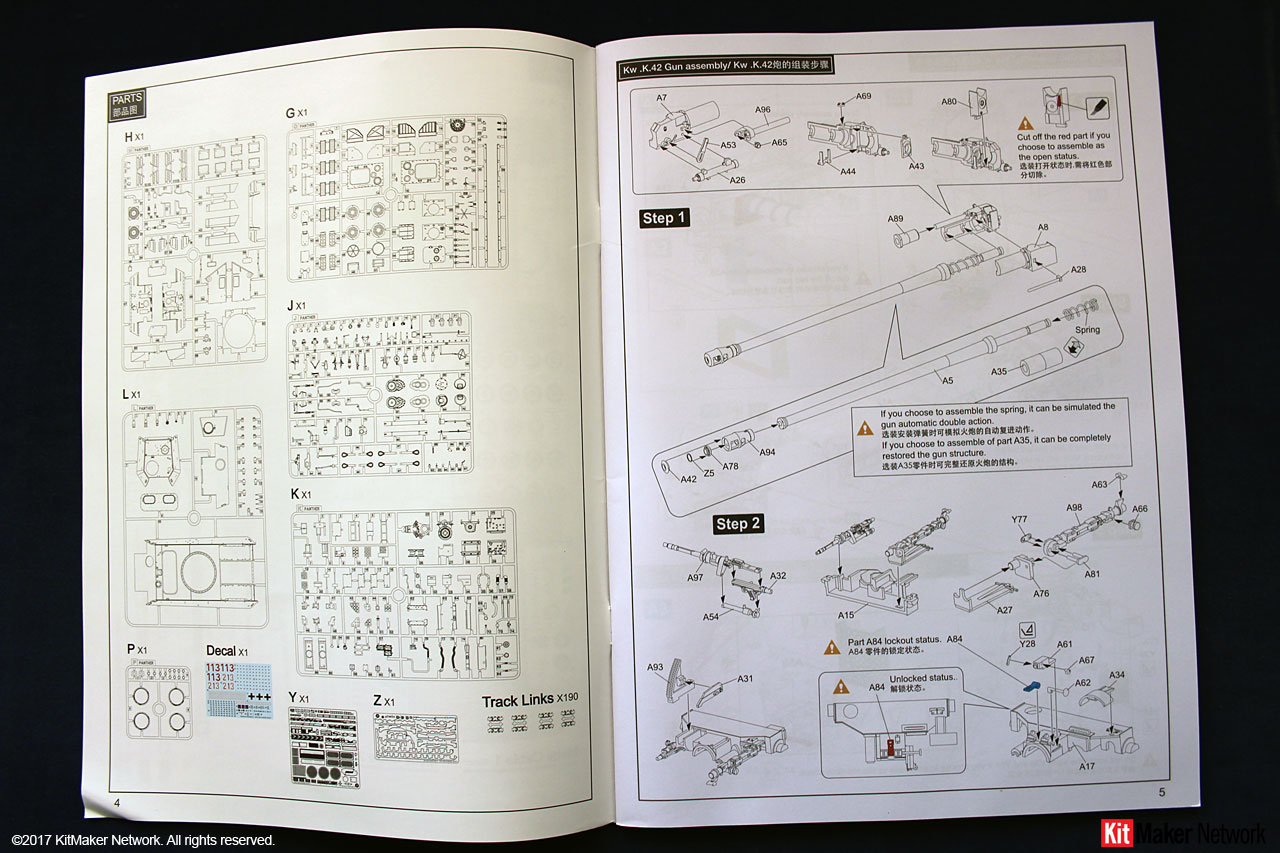
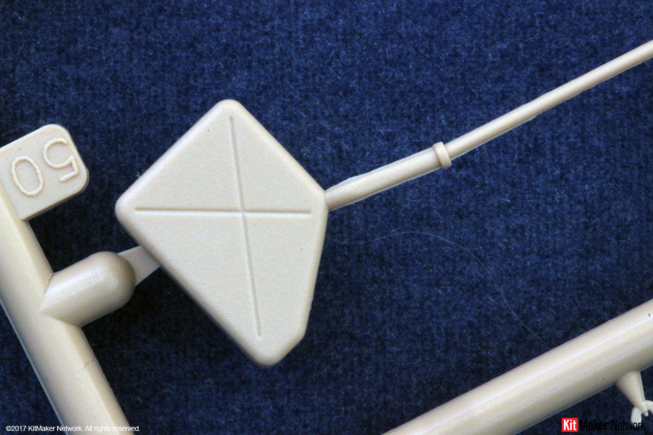
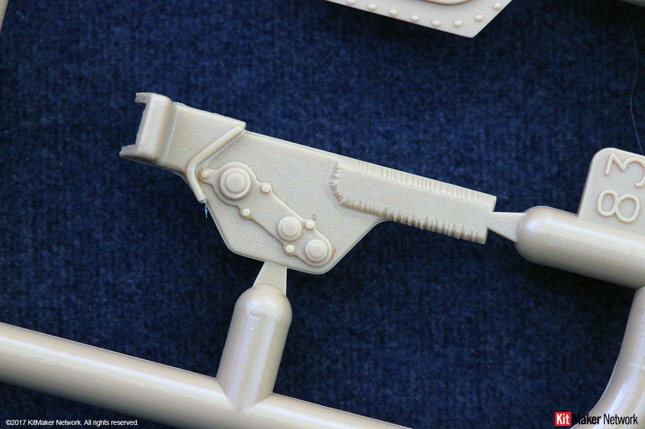
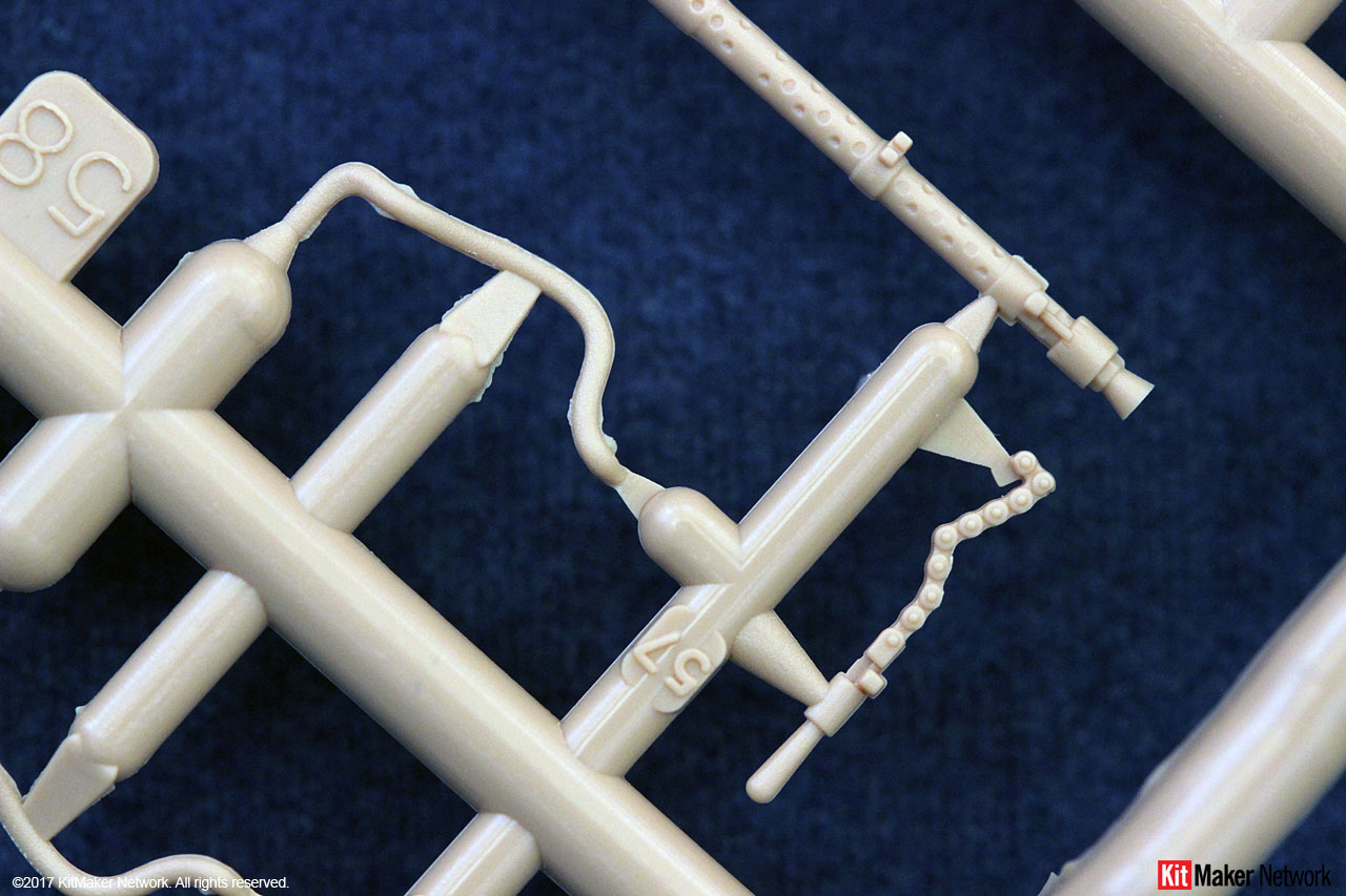
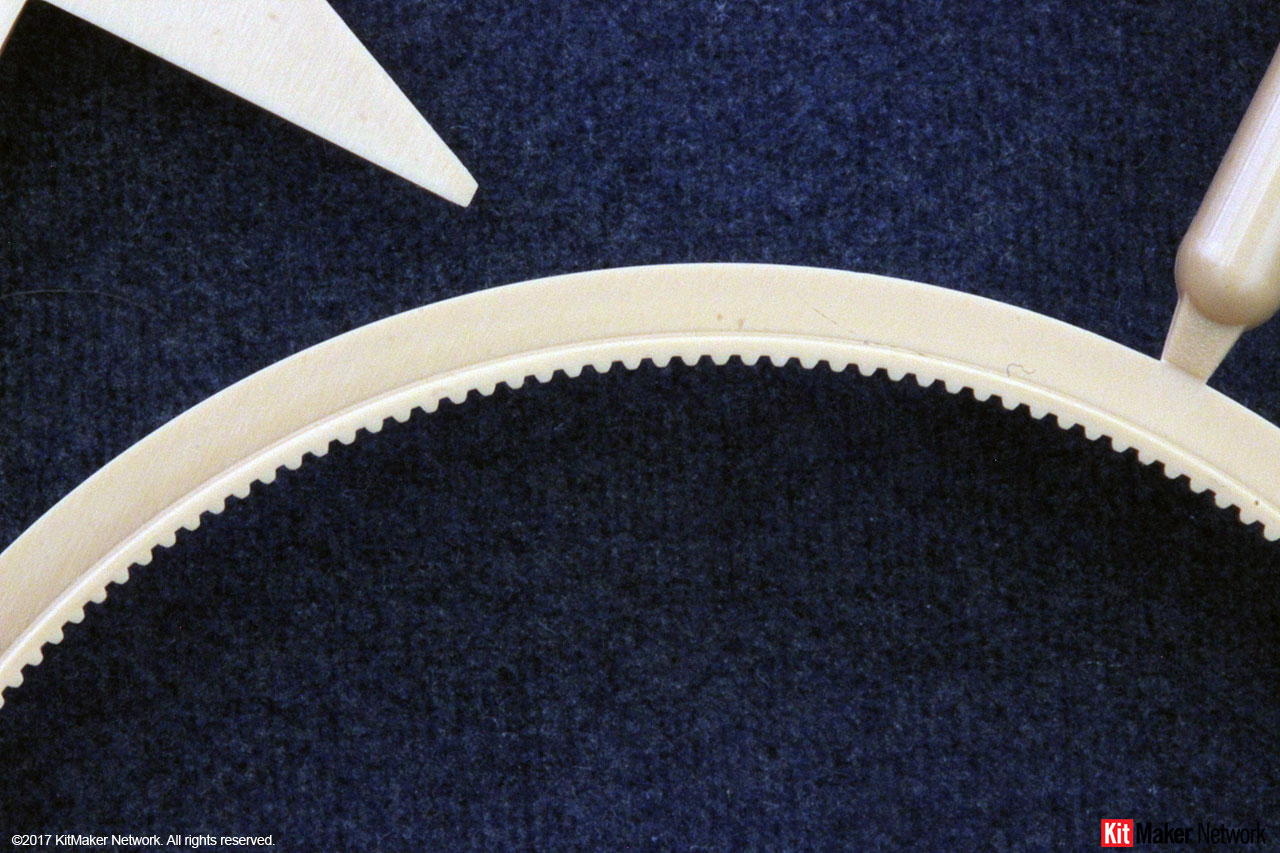
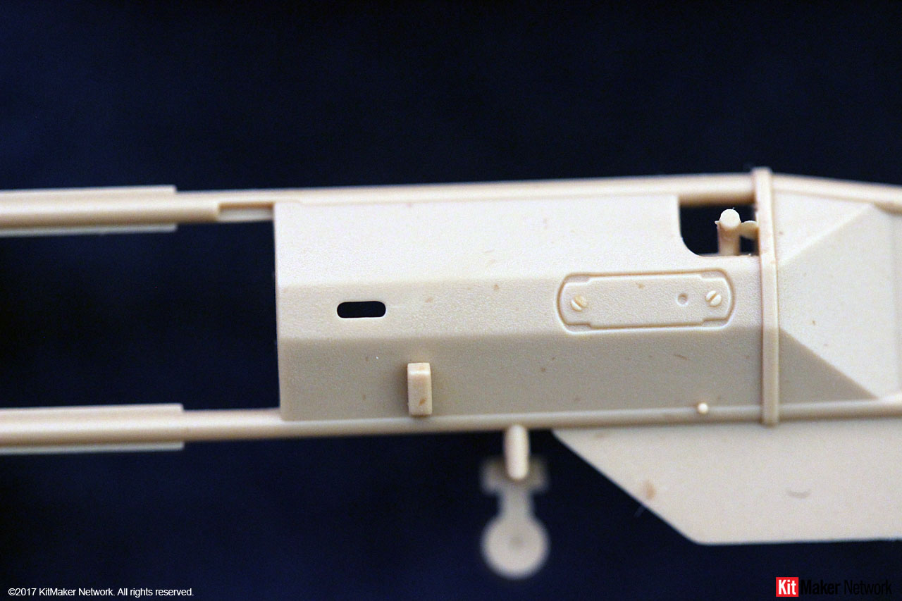
Step one gives you your first decision. This step assembles the barrel and breech assembly. You must decide if you will display the breech block in the open or closed position. If in the open position, there is a small tab (highlighted in red) that must be removed.
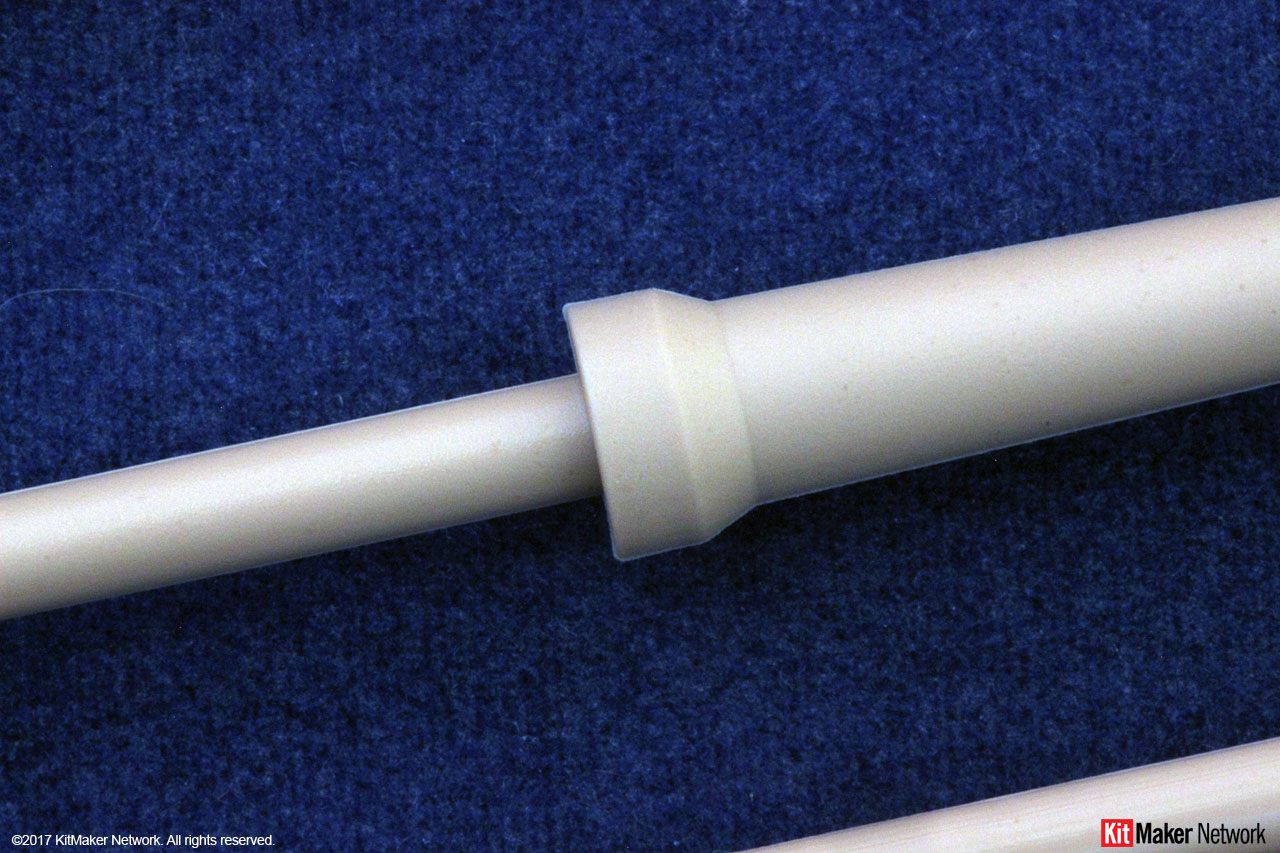
When installing the barrel, you need to choose between installing a spring or a spacer, part A35. If installing the spring, you will be able to simulate the movement of the barrel as it fires.
In step 2, you need to decide if you will display the gun assy. in the unlocked or travel locked position with part A84.
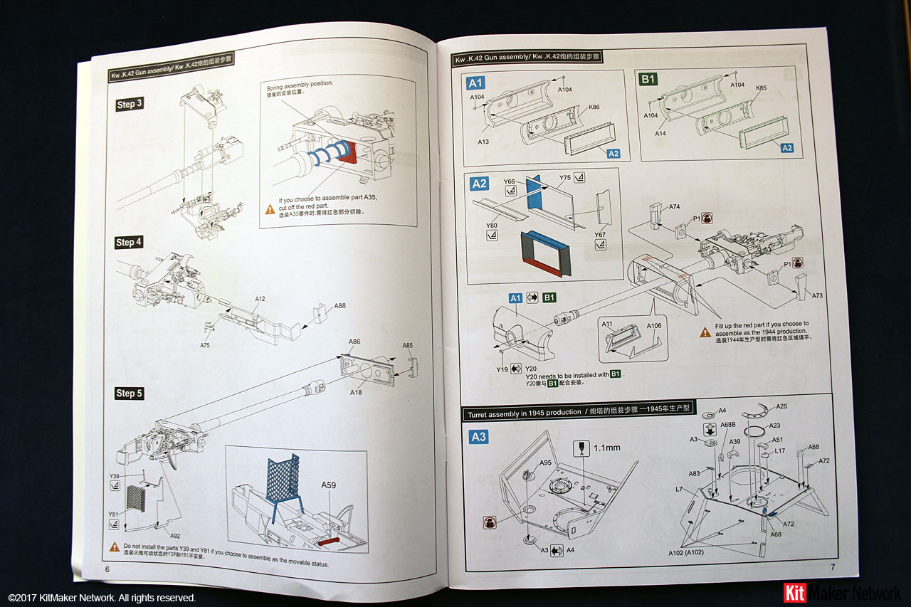
In step 3, you need to remove the tabs (parts A15/17) if you installed part A35 on the barrel. Remove these tabs before gluing the two parts together.
In Step 5, if you installed the spring on the barrel, then parts Y39 and Y81 should not be installed.
Page 7 of the manual provides for your first configuration decision. Sub-assemblies Step A1, A2, and B1 are still part of step 5. Step A2 is all PE parts that must be folded to fit together. No specific folding instructions are provided and leave you to best work it out based on the drawing. The assembled part from Step A2 is then used with both Steps A1 and B1
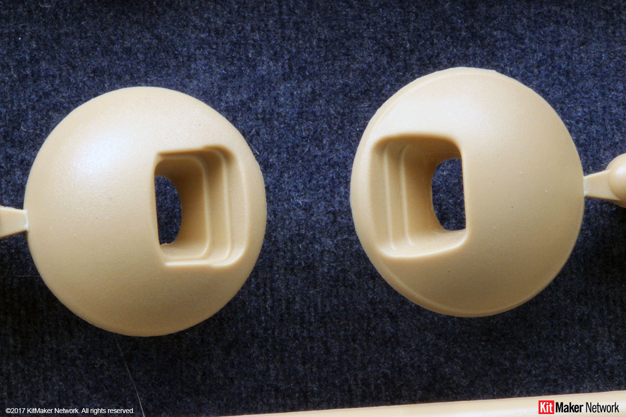
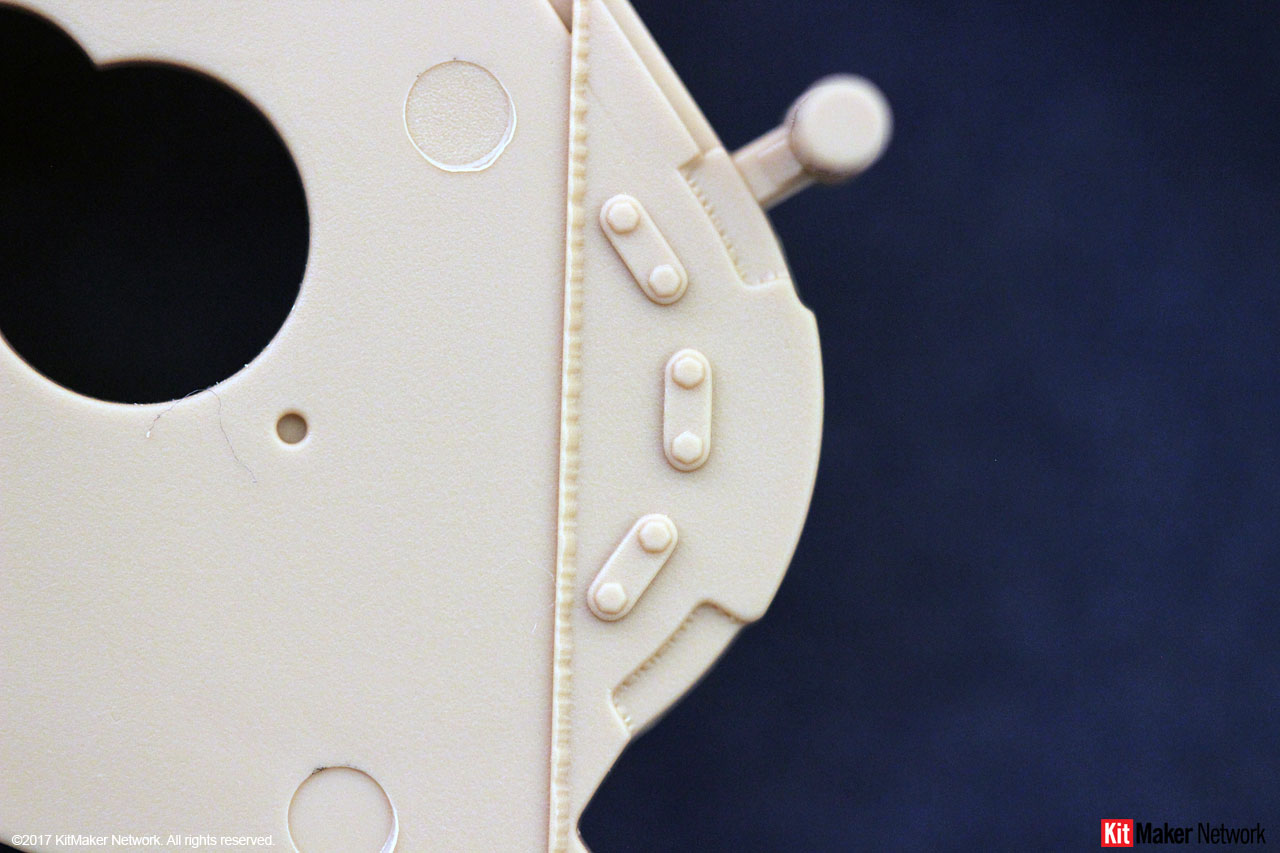
A1 is the chin mantlet, identified for the 1945 version; and Step B1 is the round mantlet identified for the 1944 version. These designations are not 100% correct. The round mantlet was installed on production vehicles right up through April 1945. You would be 100% correct to use parts A14/K85 for a 1945 build. The chin mantlet was introduced in September 1944. So you can build a 1944 version with the chin mantlet as well.
You are provided two rain guard options for the main gun sight aperture, parts Y19 or Y20. The instructions call out Y20 for the 1944 version. Therefore, Y19 is for the 1945 version. Again, not 100% correct. Part Y20 would only be applicable for a March-August 1944 configuration. A new rain guard (Y19) was introduced in September 1944. So, use the one that matches your timeline. This was also a field modification, so you can install Y19 on an earlier version and still be accurate.
Lastly, the instructions ask you to fill in two slots on the front turret armor panel for the 1944 version. These slots are for attaching the debris guard. This part was introduced in August 1944. Plus, this was an approved field modification. So, install at your discretion for a pre-Aug 44 version.
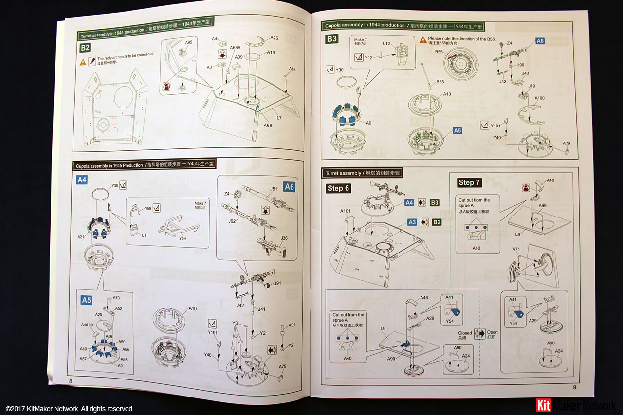
Next are the turret roof options. For the 1944 version (Step B2), the manual has you make several changes to the turret. It has you remove the Pilze sockets; fill in the holes for part A102; and surface locators for parts A51 and A72. Since the turret is a clear part, doing any of these actions will impact the visual quality of the turret. Of course, if you plan to paint the turret, then there is no issue.
The Pilze sockets were incorporated into production in June 1944. It was also an authorized field modification released the same month. Only remove if you are building a version where they havent been installed.
Part A51 is the Orterkompass mount and was introduced to production in late August 1944. So, install based on your timeline.
Part A72 is the Lost Erkennungstafeln (poison gas detector panels). These were also introduced into production at the end of August/early September 1944. So, install based on your timeline.
The 1945 version (Step A3) has you install the turret rings for attaching camouflage, 5 per side. M.A.N. and M.N.H. started installing these in late December 1944. Daimler-Benz never installed these to their turrets. So, add based on your timeline.
Next are options for the commanders copula. A 1944 (Step B3) and a 1945 (Step A4/5) version are shown. The commanders periscopes had a new frame and fastener incorporated in July 1944. So the called out kit part L12 can be replaced with L11/Y59 for a 1944 configuration.
For the 1945 version, it has the post mount for the AA MG. The post wasnt incorporated until March 1945. So, use the 1944 parts if you wish for an early 1945 version.
Step 7 has you install the rear turret hatch handle (A90). This was incorporated into production, as well as an approved field modification, in June 1944. Add the handle based on your timeline. Prior to official approval, field workshops were installing a handle on the hatch without authorization dating back to the Ausf. D.
In regards to Steps A7 and B4 I couldnt find any detailed information on these changes. It looks like the parts are related to the commanders observation periscope. If so, the mounts were ordered removed, in production, in July 1944.
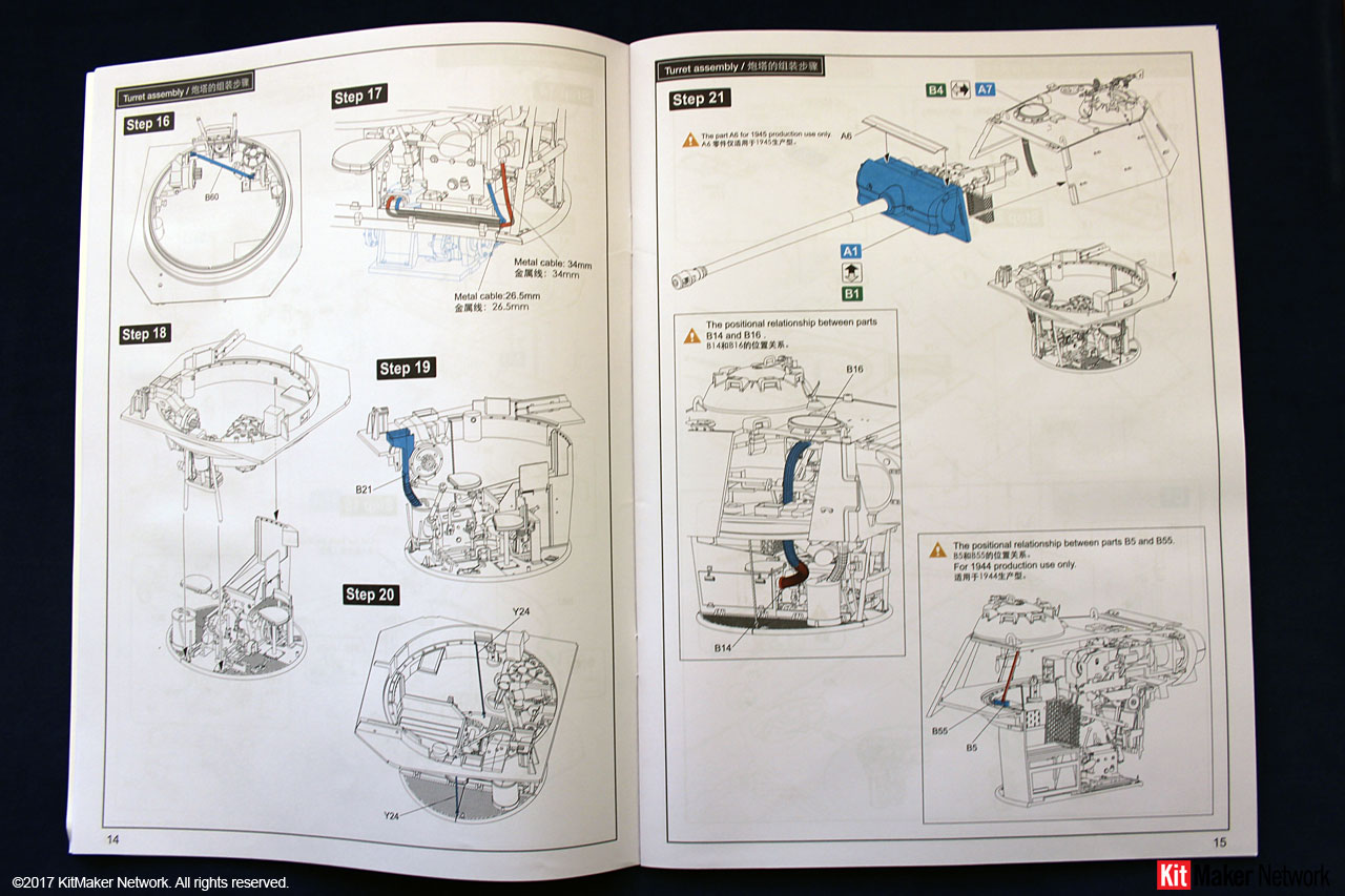
In Step 21, the debris guard (A6) can be installed in a 1944 version if you have selected that option back in Step 5.
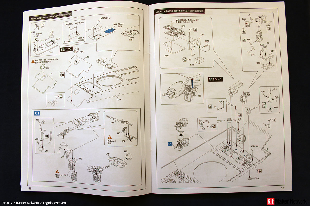
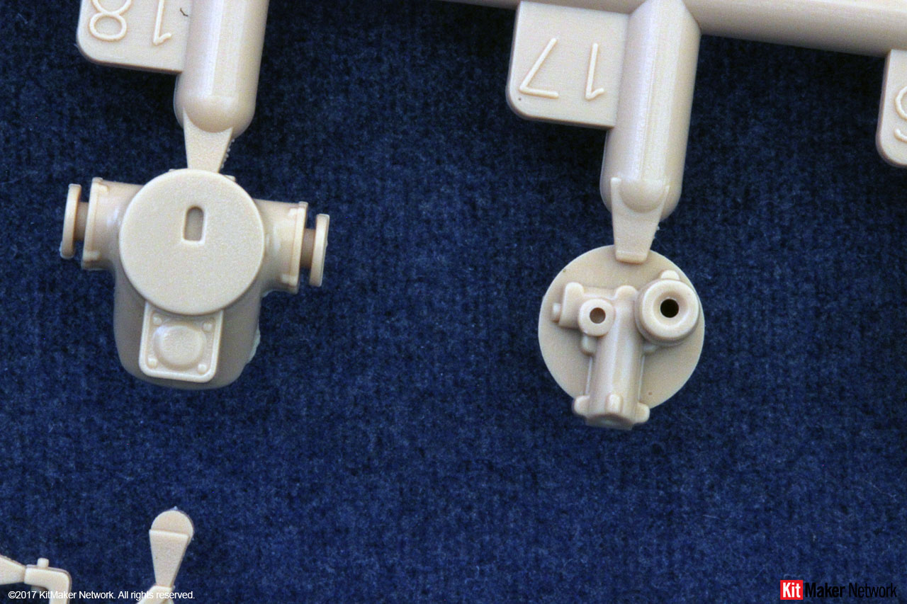
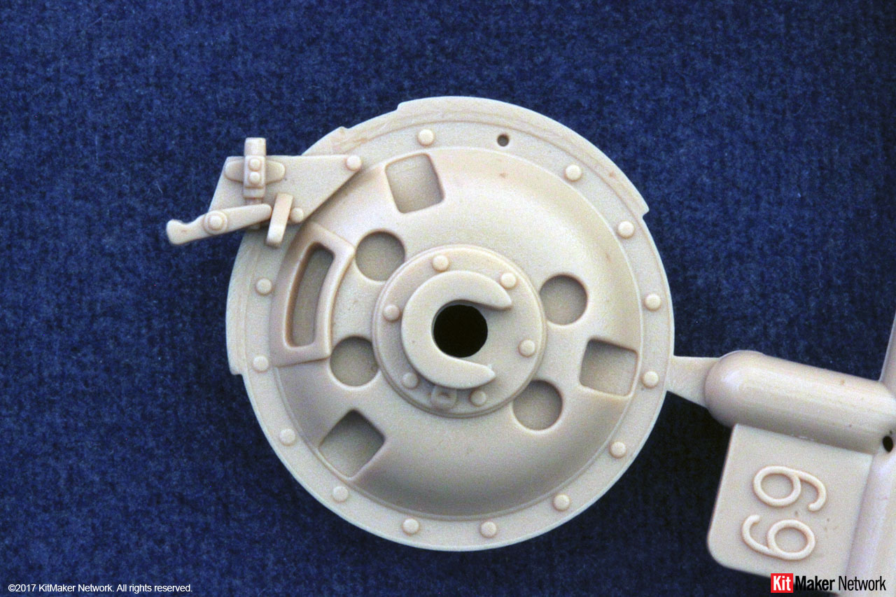
Step 22 has you install the hull MG ball mount part J66 for the 1944 version. Based on the reference material, this was never a configuration on the Panther Ausf. G. All photos from my reference material show only part J70 as the installed configuration for all Ausf. G production. So, I would recommend you only use part J70.
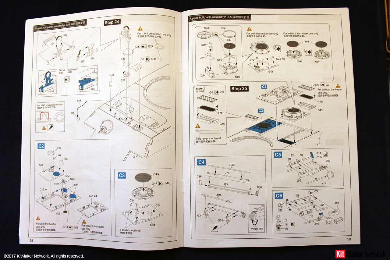
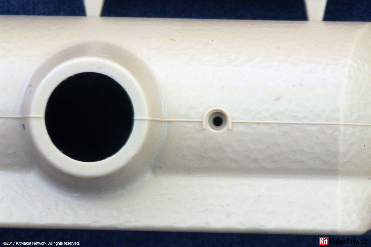
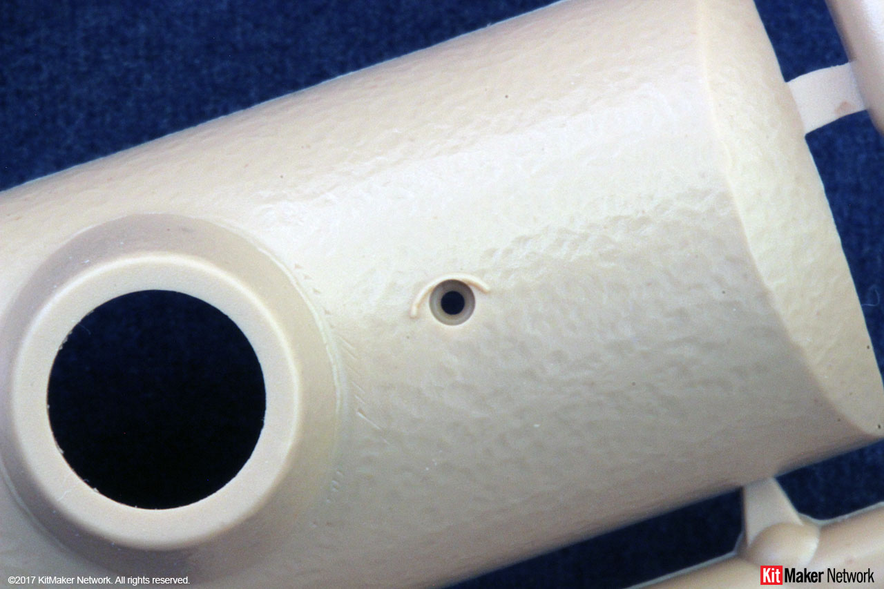
In Step 24, part G27 is the original hull ventilator armor cover. A design change was introduced on October 1944 to the new configuration, parts G21/Y86/G29. If using the new configuration, you do need to remove the indicated raised area around the ventilator. As this is a clear part, be very careful when removing.
Also in Step 24, you have the option of two cover versions over the drivers periscope. Part G34 is the initial configuration. Part G5 is the sheet metal rain cover incorporated beginning in August 1944.
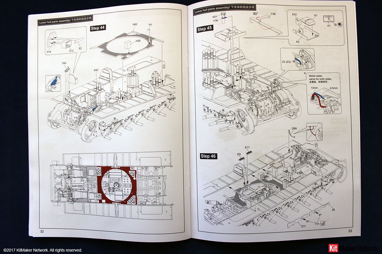
Step 25 provides the option of installing the crew compartment heater. The first vehicle to leave the factory with this installed was in mid-September 1944. Install based on your timeline.
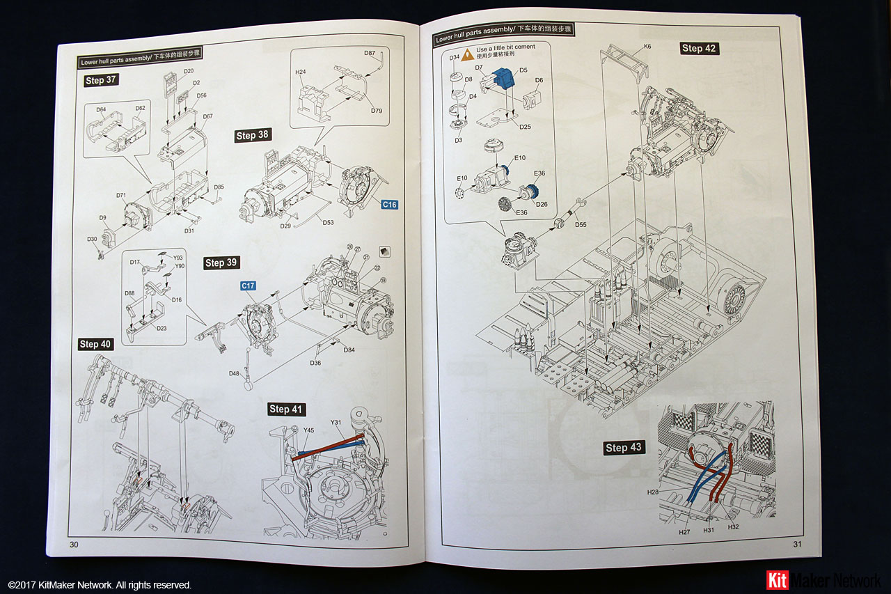
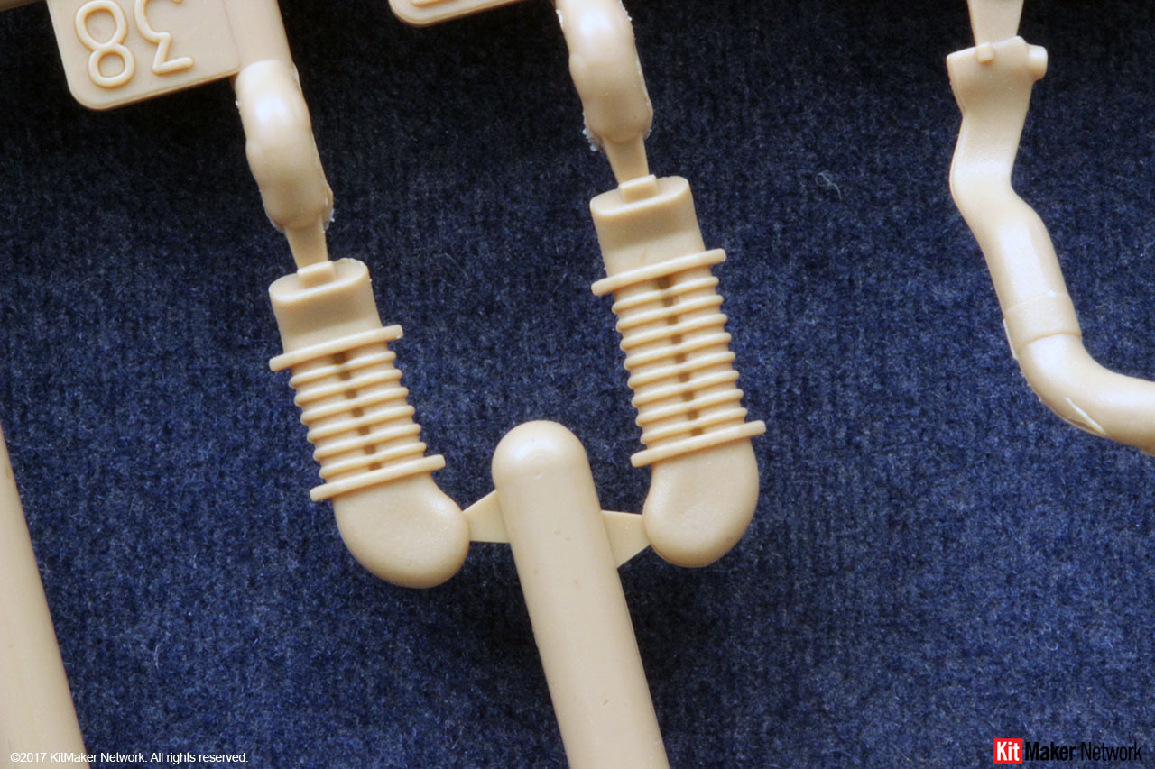
Steps 35 and 49 have you install the rear shock absorber. On October 7, 1944, the factories were ordered to immediately stop installing these. So, install based on your timeline.
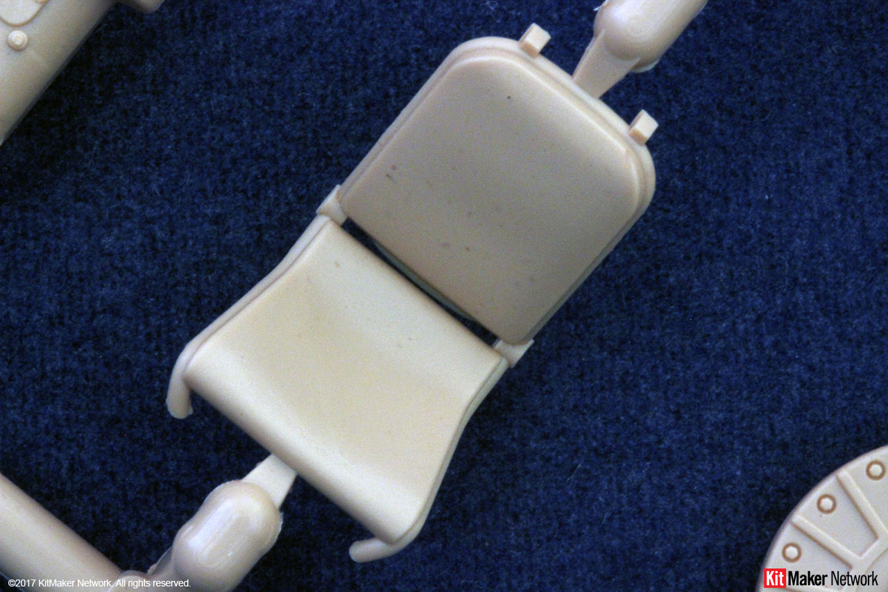
Step 35 also assembles the drivers seat. The elevated seat, parts D10/D21, entered production in October 1944. If building an earlier version, then you will also need to modify the pedal assembly to remove the extensions used with the elevated seat.
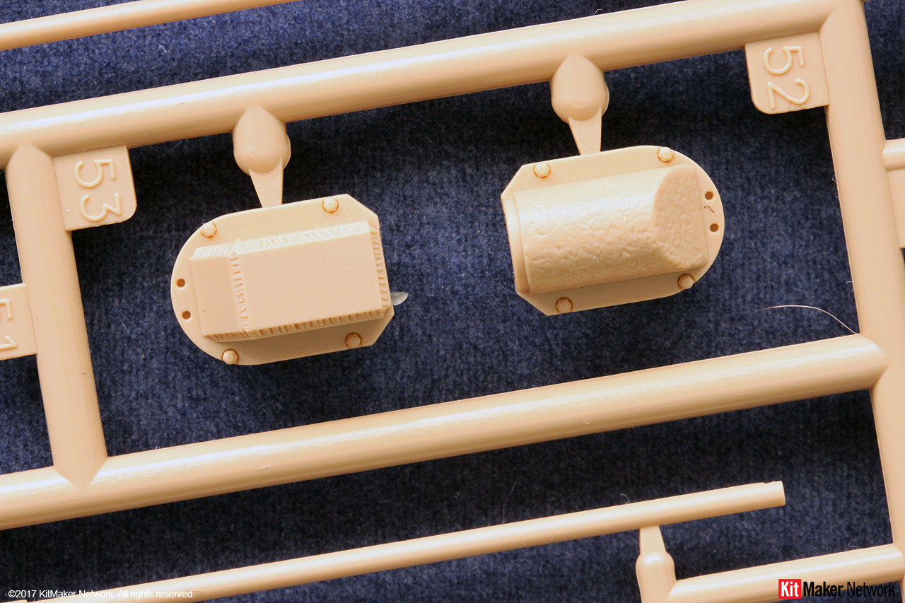
Step 65 requires you to select which exhaust version you want to install. Steps C27/29 is the original Ausf. G configuration with cast covers. In July 1944, the sheet metal covers were added, part C33. So, only the very early production vehicles did not have the sheet metal cover.
Steps C28/C30 has the welded covers introduced in May 1944. In July 1944, the sheet metal cover was added, part C33.
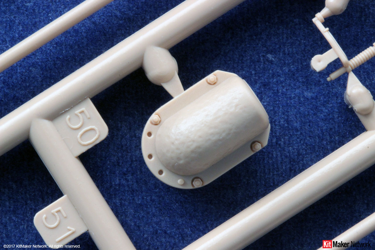
Steps C23/C24 is the initial Flammenvernichter exhausts authorized for production in October 1944. However, factories didnt begin installing them until late November or early December due to availability.
Steps C25/C26 is the Flammenvernichter exhausts with the welded cover seen on vehicles produced starting in December 1944.
Step C31 is the rear storage box specific to the IR configured Panther Ausf. Gs. As this kit does not include any of the other required IR related parts, you probably should not install this. These were installed starting in September 1944 on the IR designated Panthers.
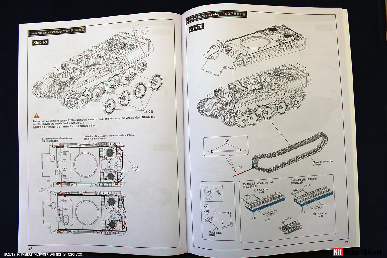
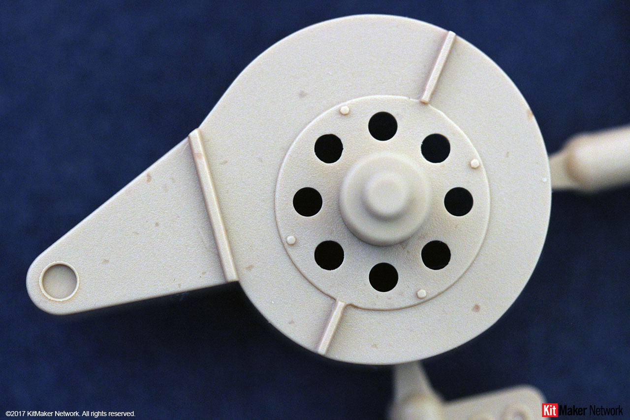
Step C33 provides you the option of installing the return roller (C14) or the skid shoe (C36/37) on the Final Drive Cover. On 1 June, 1944 instructions were issued to switch from the wheel to the skid. On 6 June, 1944, Instructions were issued to cancel the 1 June order, and continue with the rubber wheel.
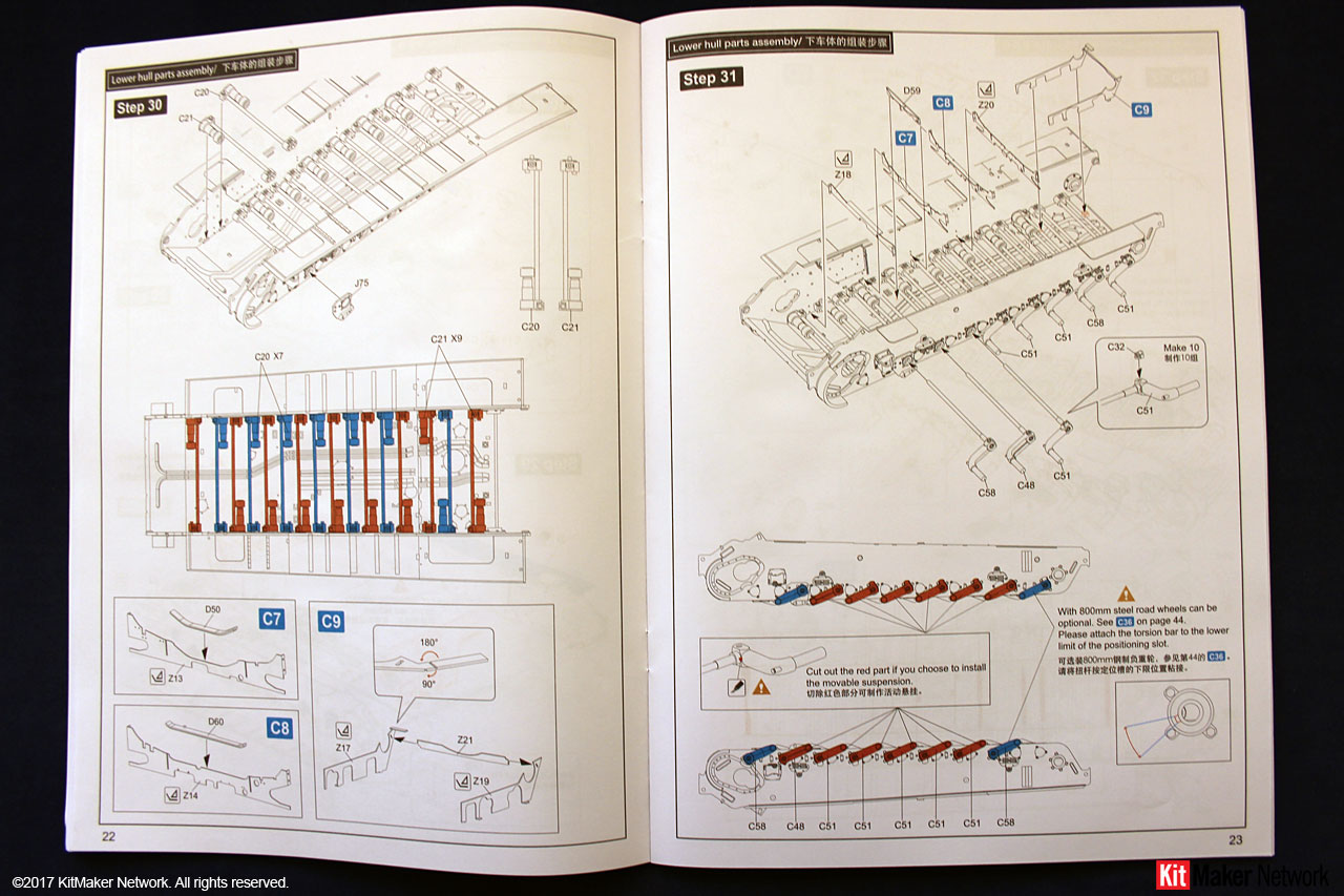
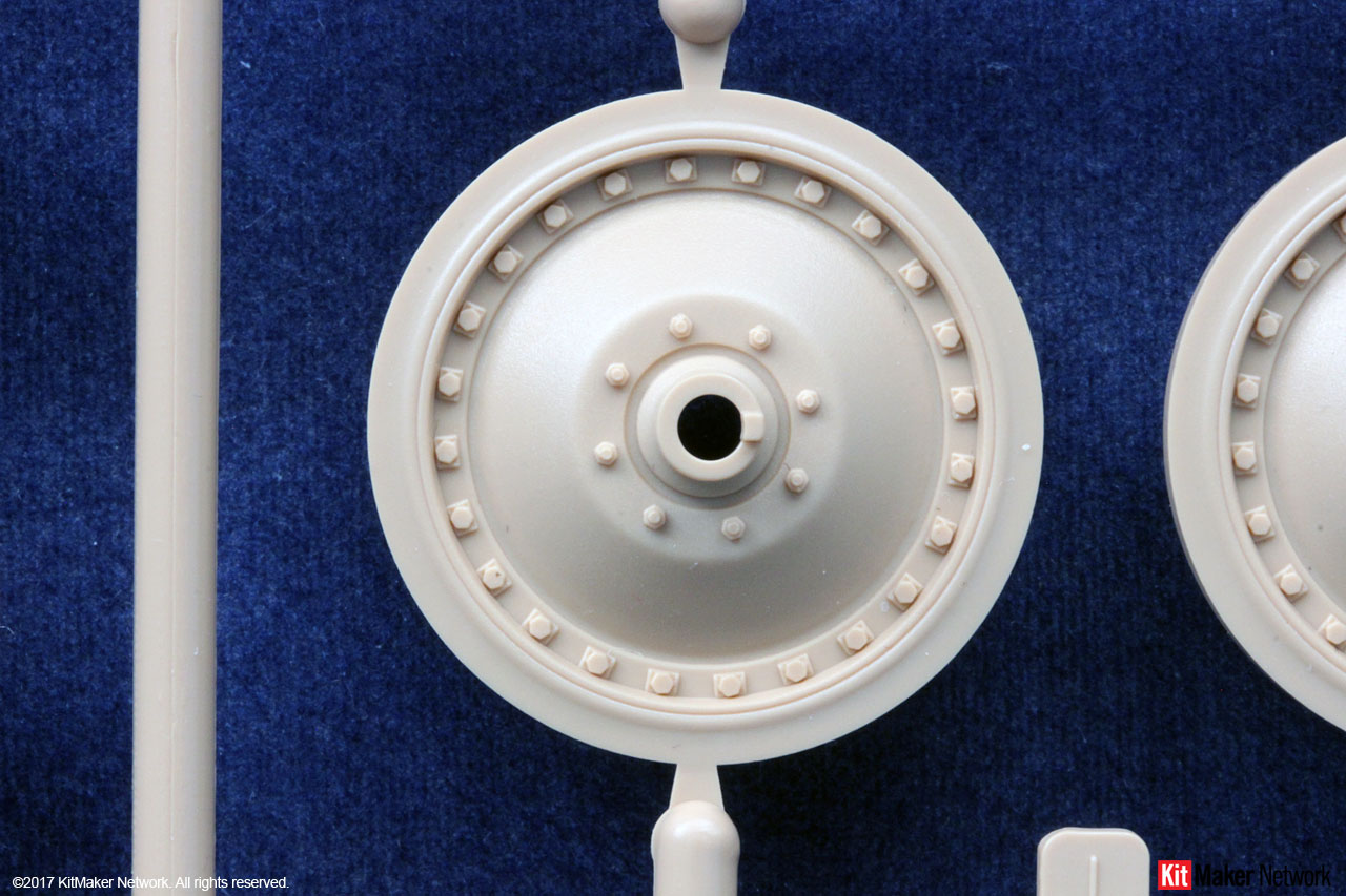
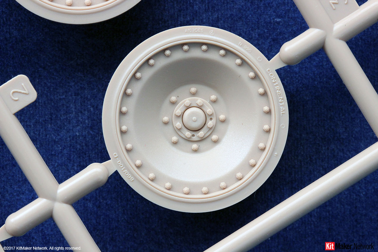
Step C36 gives you the option to assemble a set of the 800mm steel road wheels. M.A.N. assembled an unknown number of Panthers with these on the last road wheel station beginning in late December 1944. Most production used the normal rubber rimmed 860mm road wheel through the end of the war. If you select this option, then you need to also modify the installation of their torsion bars in Step 31.
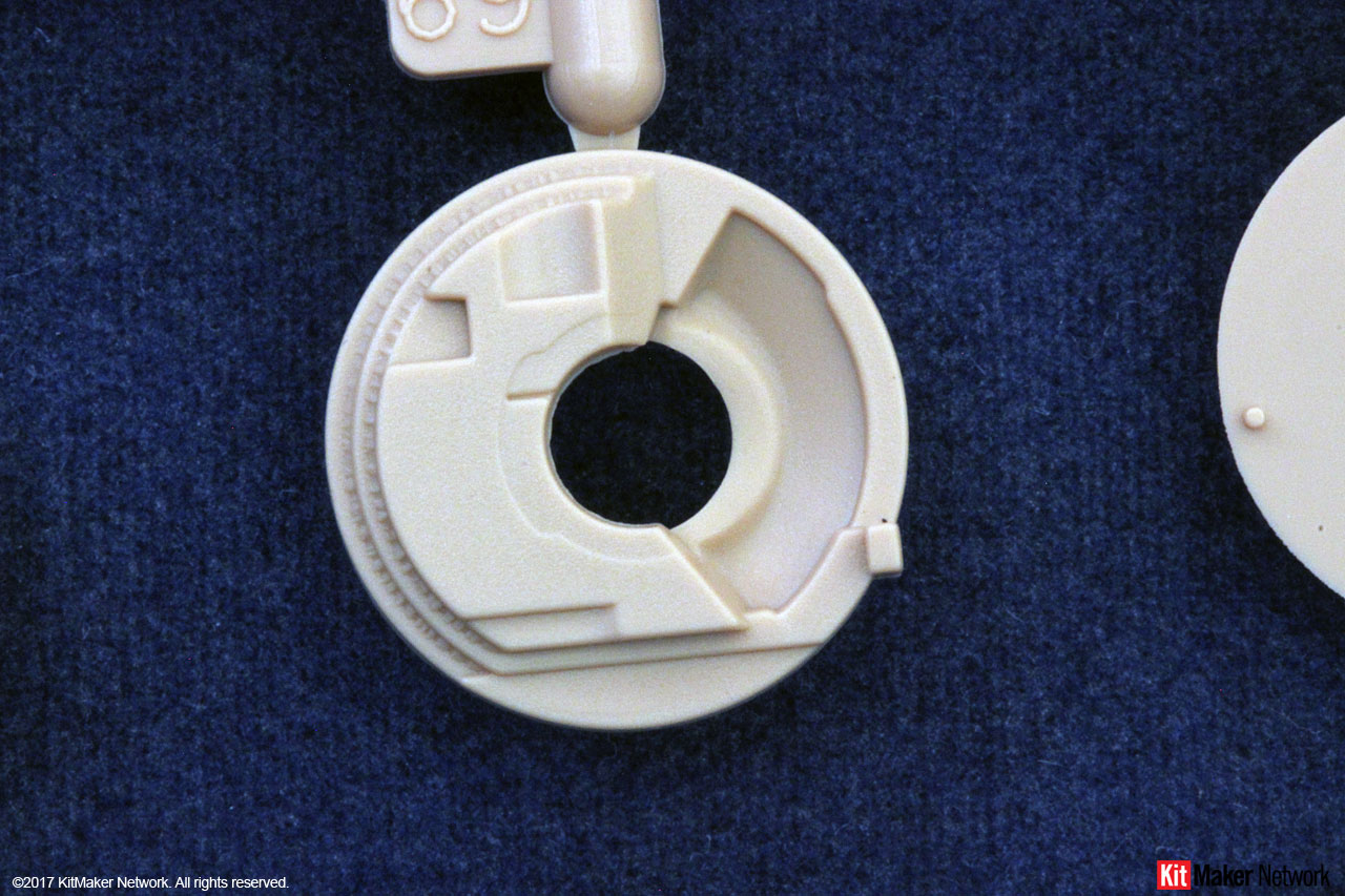
Step B5, is identified for the 1944 version. This is the original 600mm Idler Wheel. Photos show that his was installed right through to the end of the war. So, you can use this for a 1945 version as well.
Step C35 is identified as the 1945 version Idler Wheel. However, the 665mm Idler wheel was introduced into production in October 1944. So, you can build a late 1944 vehicle with this version.
Steps C37 and C41 provide you with road wheels for use in a diorama. They are not used with the kit.
Painting RFM color call-outs reference Ammo-MIG products. Call-outs are NOT identified during the build process. There are two pages in the back of the manual that identify painting recommendations for the turret and chassis interior.
RFMs interior painting guide shows the initial multi-color scheme. On August 25, 1944, the factories were ordered to immediately stop applying this scheme. The interior/turret was to be left in the red oxide primer (RAL8012/3) with the upper surfaces in Elfenbein (RAL1001).
At the end of October 1944, instructions were issued to stop all painting of the interior/turret and leave it in the red oxide primer (RAL8012/3).
In mid-February 1945, instructions were received to apply the Elfenbein (RAL1001) to the interior of only the turret. This would indicate that the hull interior remained red oxide primer (RAL8012/3).
This sequence of changes is based on documents found at M.N.H. However, logic would say that the same instructions would have been issued to the other two factories as well. At the end of the day, it is your build, and paint how you desire.
Camouflage patterns are always a discussion with the Ausf. G Panthers. Here is a summary put together from the reference books listed below. I dont claim it to be 100% perfect. Ultimately, paint the model any way you want. It is your model.
The three factories received, on August 19, 1944, the General Order to begin applying a standard camouflage pattern before shipping to the front. The word standard is not completely correct. Each factory applied a slightly different standard pattern. Even within a specific factory, the standard pattern changed many times.
Since this kit represents a M.A.N. production vehicle, Ill only list the evolution of their identified standard camouflage patterns.
Late August 1944 Ambush or disc scheme (zimmerit vehicles)
Early September 1944 Acrylic Paste scheme (zimmerit vehicles)
September 1944 Classic initial scheme (non-zimmerit vehicles)
October 1944 Classic modified scheme
Late November 1944 Vertical scheme
Early December 1944 Wide band vertical scheme
December 1944 through April 1945 A combination of the classic and vertical scheme
Around mid-September, instructions were received to apply the three colors directly over the red oxide primer. When each factory begin complying is unknown. The normal application of the Dunkelgelb (RAL 7028) basecoat was discontinued. Probably to conserve paint stocks.
Decals Options are provided for three different vehicles:
No. 113, 1.Panzer Regiment 2, 16th Panzer Division, Oberschlesien, March 1945
Unknown Unit, Germany, January 1945 (Camo scheme with sawtooth whitewash)
No. 213, 2.Panzer Regiment 31, 5th Panzer Division, East Prussia, October 1944
Reference Books
These books are highly recommended if you are looking for good reference material.
1 Panzer Tracts No. 5-3: Panzerkampfwagen Panther Ausfuehrung G
2 Germanys Panther Tank: The Quest for Combat Supremacy
3 Panther: External Appearance and Design Changes
4 Feist Books: Panzerkampfwagen Panther
5 The Panther Project Vol 1: Drivetrain and Hull
6 The Panther Project Vol 2: Engine and Turret
At Andys Hobby Headquarters, YouTube channel, Andy has a two-part build video of this kit that I strongly recommend you view before starting your kit. He identifies a number of assembly issues and ways to resolve them.
SUMMARY
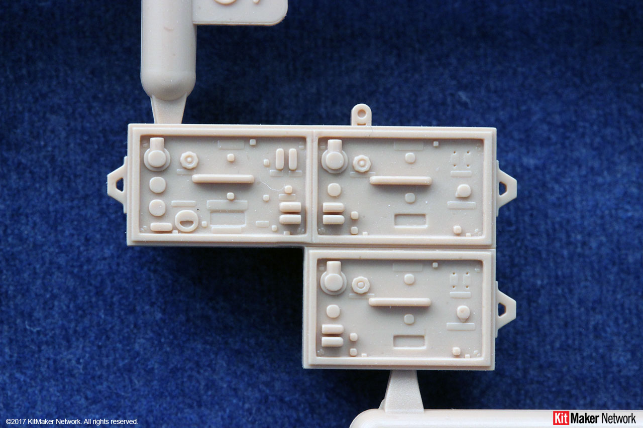
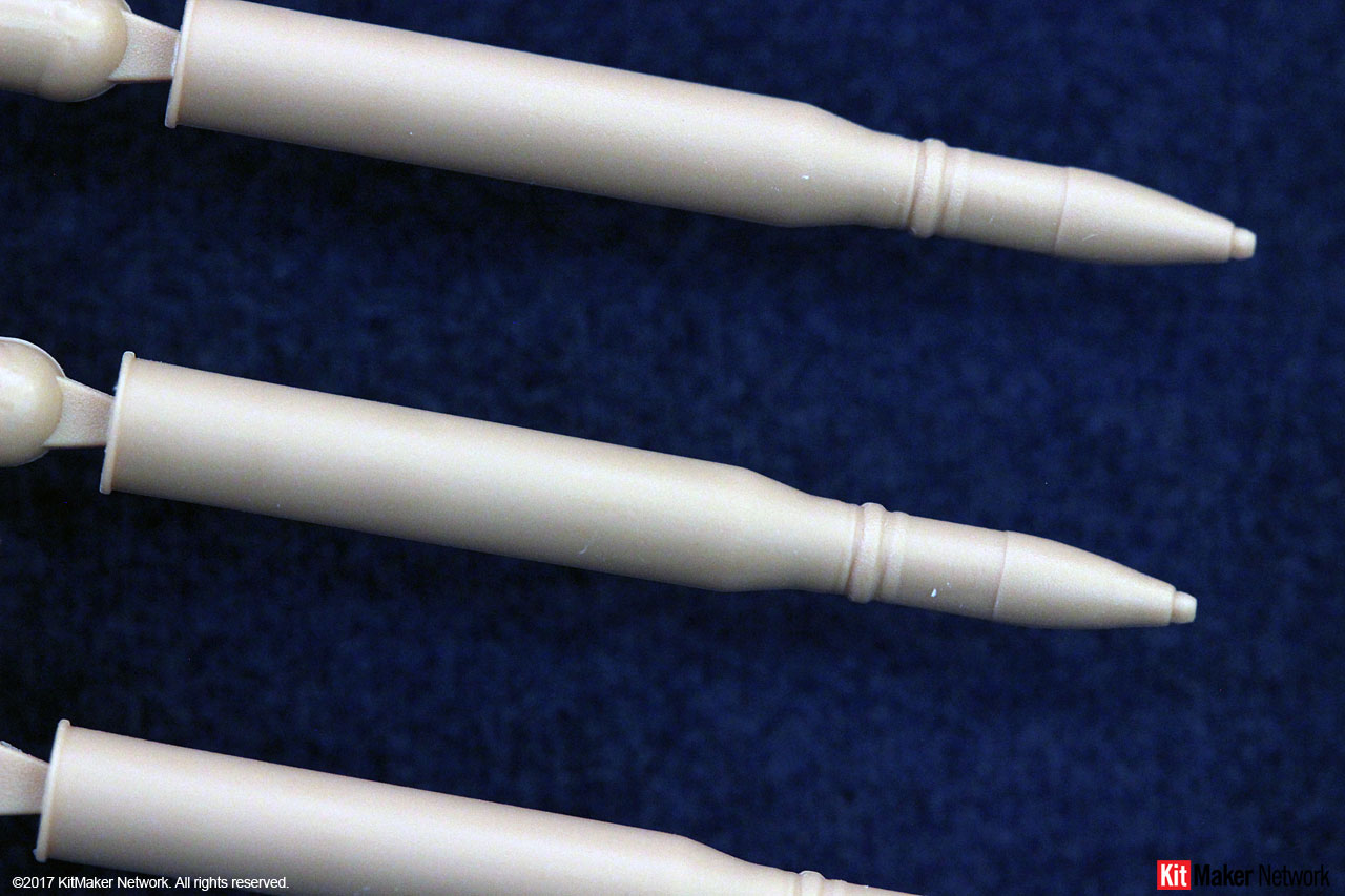
Highs: A very detailed interior is represented. Clear parts are very nicely molded. Individual shells allow the builder to display a loadout to his taste. Optional parts for diorama use. Suggested weathering steps are provided for with the included paint schemesLows: Barrel and muzzle brake are not slide molded parts, or even a metal barrel. Errors are in the instructions regarding 1944 vs. 1945 configurations. No schurzen option included.Verdict: This is a beautifully molded kit of the Ausf. G variant.
About Mark (d111298pw) FROM: OKLAHOMA, UNITED STATES
I'm from the US, but have lived most of my adult life around the world due to my work.
I started building models when I was 6. Took a 30 break as other priorities took hold (work,family, etc..). Got back into it a number of years back building F1 kits (Ferrari only). When I got to India, the modell...
Mark, Your review cleared up some of the questions I had about production differences and timeline, and helped clarify the instructions. Along with Andy's videos I think i know how to approach this build. Just knowing I can keep the interior painted in mostly one color means I can build more and paint less. I have to say RFM did a much better job on this kit than they did on their M-1. That one should be called a basic interior kit, this kit has so much more detail. I'm starting to get hooked on these interior kits. Thank You very much for a great review. Mark
Very nice and informative review Mark.
I was lucky enough to receive the review kit from Darren and Jim. I was just about to turn in my write up and pictures for it. With you permission, I wanted to adjust my wrote up to incorporate some of your key points before I turn it in. My write up is more a build feature then a review.
Pete,
Darren and Jim combined Jim's video review and pics with my review, so, go ahead and use what you need for your review. I look forward to reading it.
Thank you Mark, for this detailed examination of the Panther G kit, and the timing couldn't be better as mine arrived just recently and I'm dying to get started but -oddly- not sure where to start...still, it'll be a fun challenge. The review answered a lot of questions that I had and raised a few points that had yet to occur to me!
I'm really interested in this kit, so I have followed this review carefully. However I can't see, or have missed whether the clear hull parts have moulded on Zimmerit. If they don't, that scuppers modelling an early G, unless you want to cover the clear portions with AM Zimmerit or putty, which will defeat the object of them. The photos of the clear parts don't look as though they do have Zim.
The clear parts do not have a zimmerit pattern molded. Such a pattern would distort the ability to clearly view the interior. Also, any production Ausf. G from late September 1944 through the end of the war, would not have zimmerit. The kit is designed to have the ability to model any version of the Ausf. G. Molded zimmerit would not allow a post 9/44 version. The other option would be for RFM to include two sets of the affected parts, a la Dragon's 2 in 1 kits.
It would have been nice if RFM provided a separate decal set (like Meng) for this purpose. If you want to add zimmerit, you will have to do so manually (putty method) or go aftermarket.
Frank,
I had the same reaction when I received mine. I had no idea where to begin. After going through every step of the instructions, and looking through my reference books, I started making notes for all the options. Those notes became this review as I figured it my be helpful for others in the same situation.
I'm waiting to read Pete's build review before I get started on mine. Still have to figure out what version I want to build.


Comments