Another build/review kit from the great guys at Armorama. When I saw how big the box was, I thought to myself what did I get myself into? Its a huge box packed with tan plastic! The parts count is as much, if not more than the Hobby Boss HETT kit. What was cool was that the clear turret and hull top cam in its own box to help protect from scratches and such. I won't bore you with what's in the box and things like that because Jim did a Cracking the Box video and an awesome in-depth review with information from the time period on the vehicle from Mark, aka d111298pw. I will mainly concentrate on the build and instruction corrections if any.
The Build
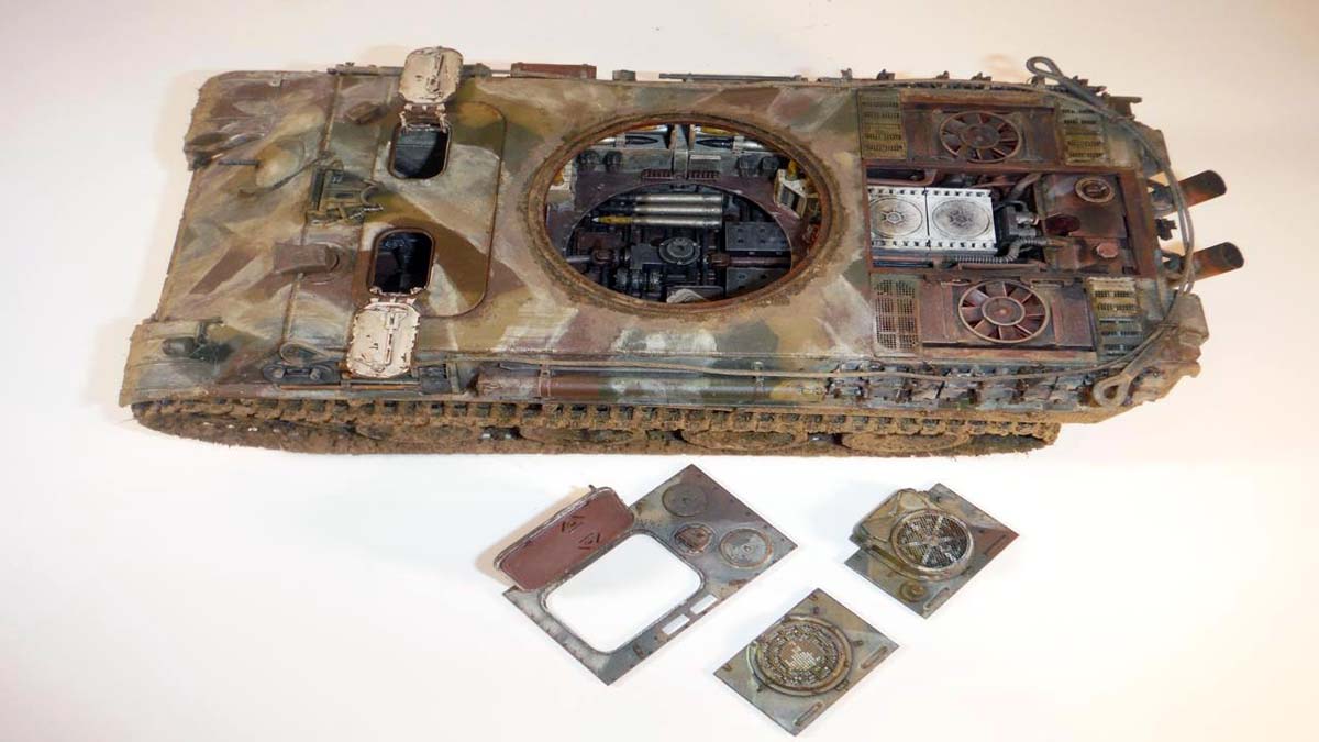
The first thing I did was go through the huge instruction booklet and decide what version I was going to do. I opted for the 1945 version as that way I didn't have to cut a lot of stuff off from the clear turret top. The second thing that needs to be decided is whether or not to use the clear hull and turret tops. After watching Andys build video at his YouTube channel, Andys Hobby Headquarters, and looking further in the instructions, I decided to paint the clear parts. Now Andy didnt glue on all the parts that are attached to the turret and hull and painted the hull around the engine deck. This allowed you to see the interior much better. So why do we/I buy a kit with all this stuff on it and dont use it, who knows. I didnt want all that extra stuff to just go inside the spares box, so I opted to paint the clear parts. Now RFM has released the kit with a solid hull and turret top. What I wish RFM had done, was to engineer the kit like their Tiger with full interior release. What I mean is they should have engineered the hull with the top deck as a separate piece. This way, you can remove it to view the interior. The same thing would have been nice for the turret roof, but I see the air duct that runs from the roof to the turret floor would be an issue.
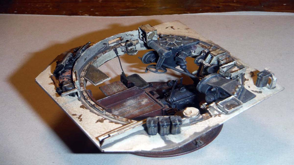
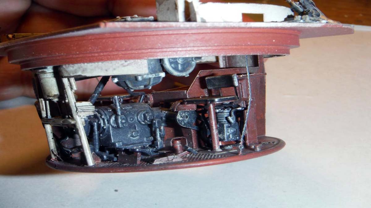
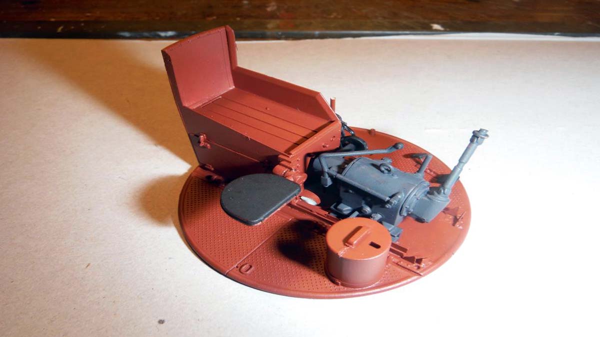
Enough with that and on to the build. This kit definitely has to be built in several sub-assemblies for ease in building and painting. So, with that, I hadn't decided how I was going to display the model once finished and started the build where the clear hull top and turret top wouldn't come into play yet. I started with the engine, transmission, and hull bottom.
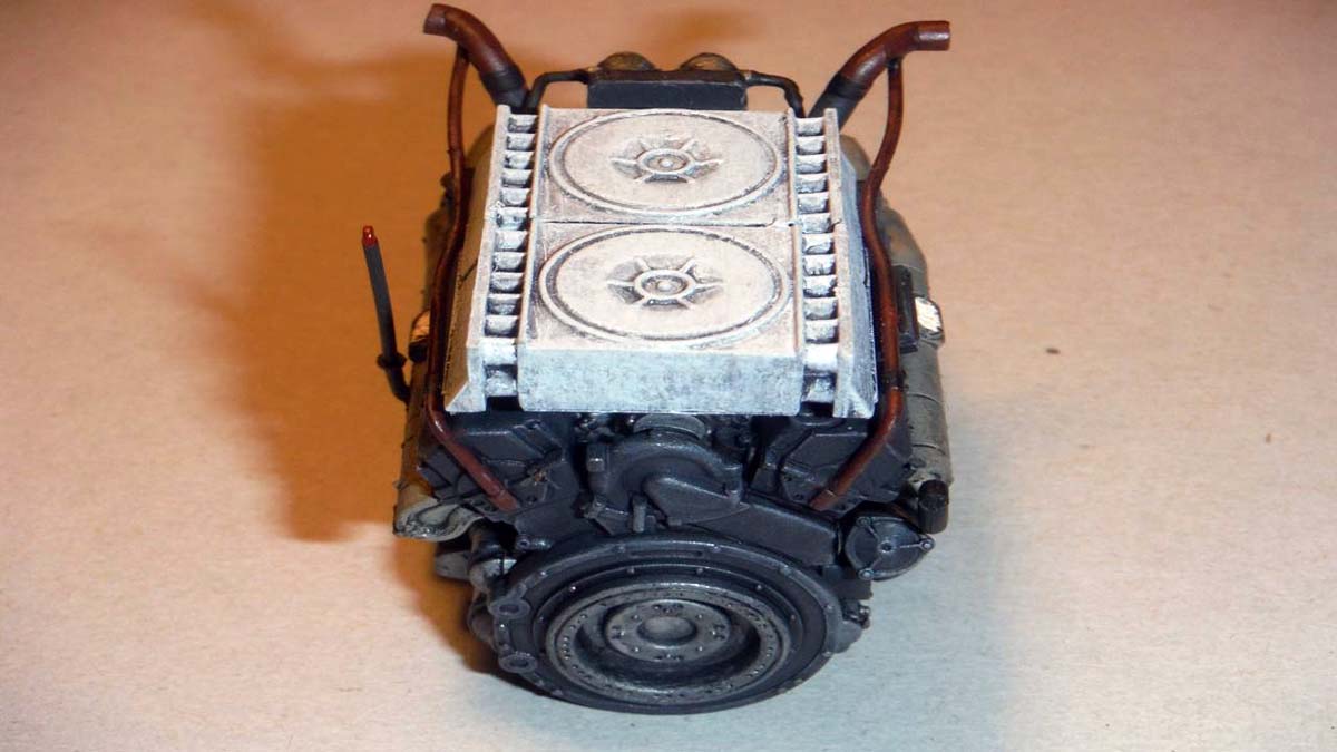
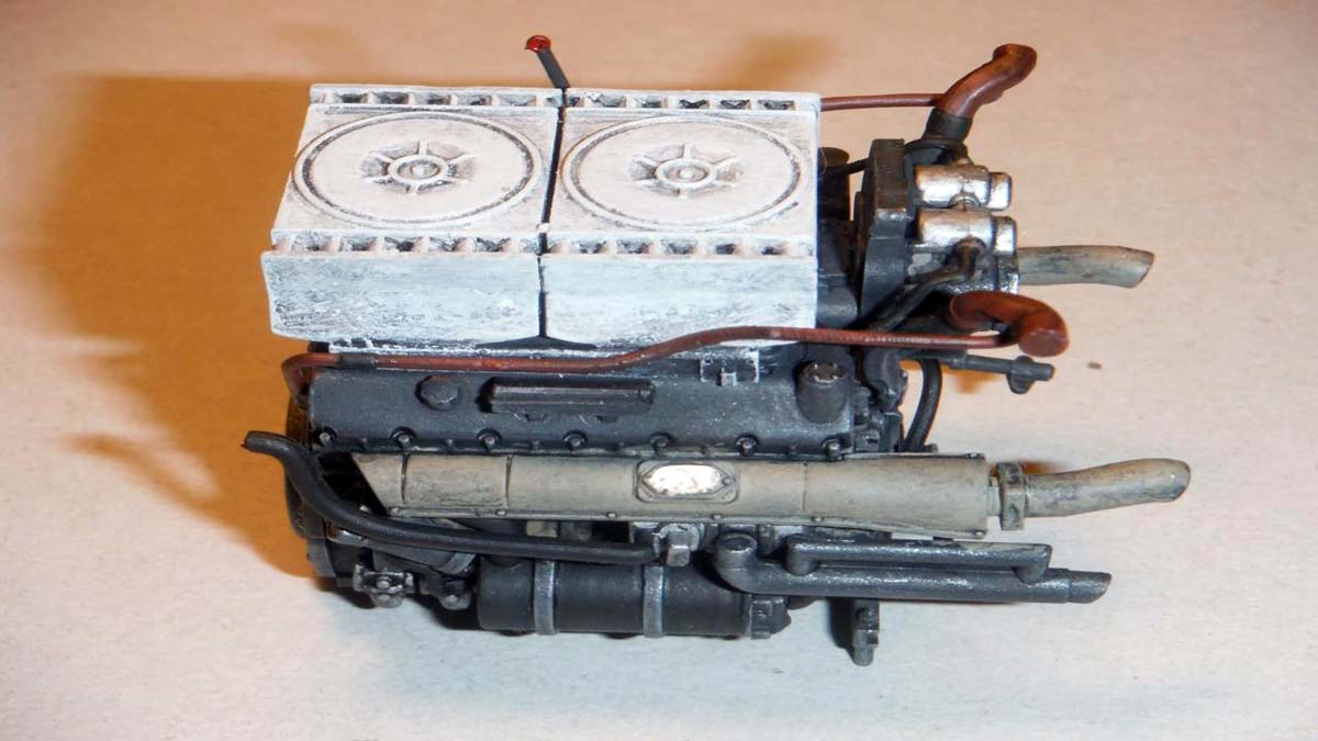
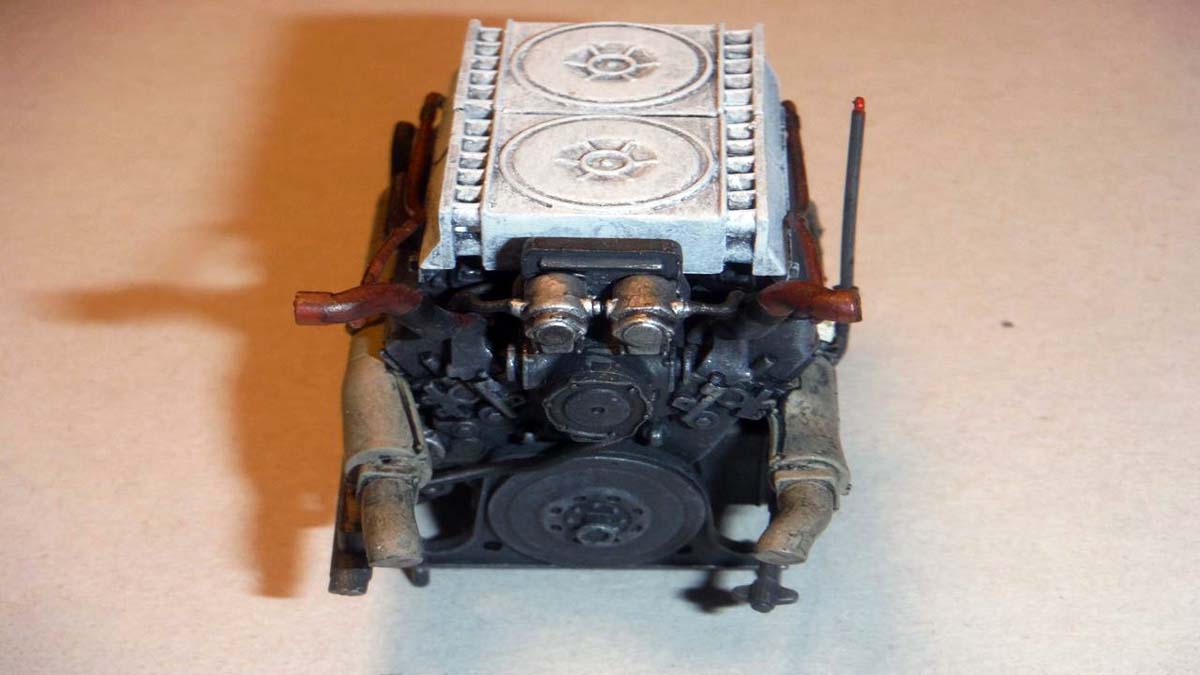
The Engine
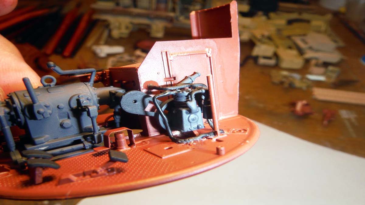
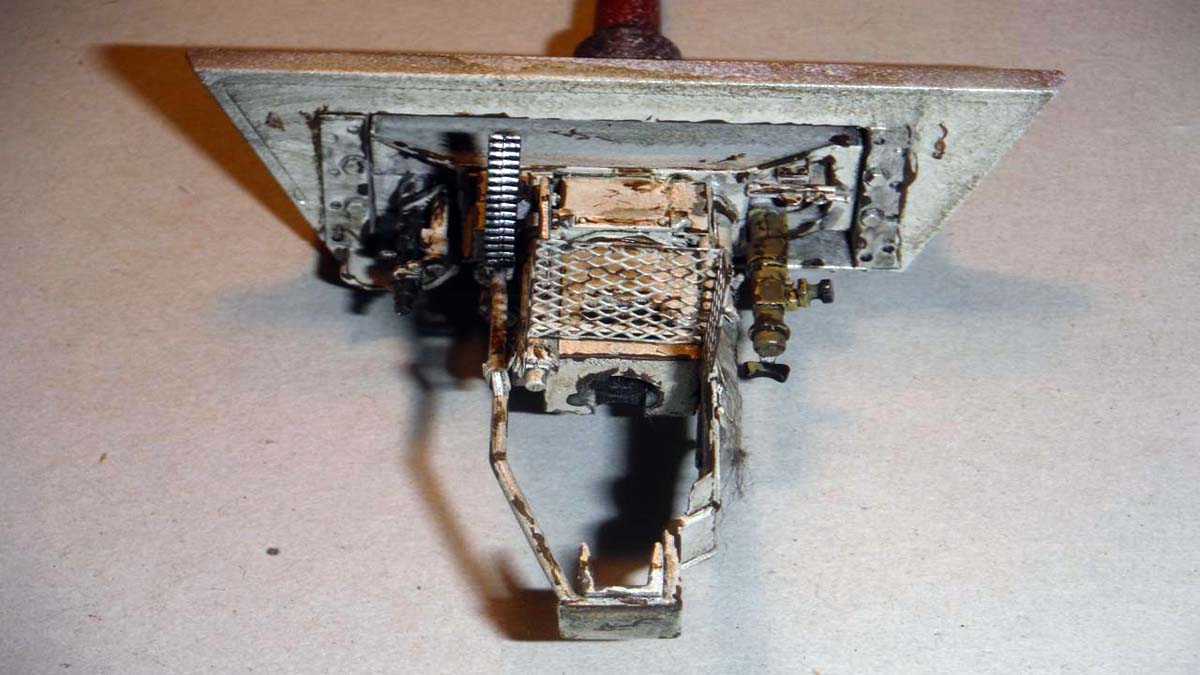
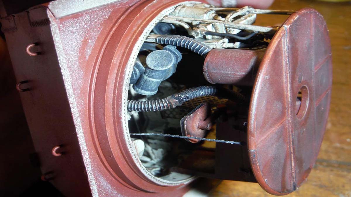
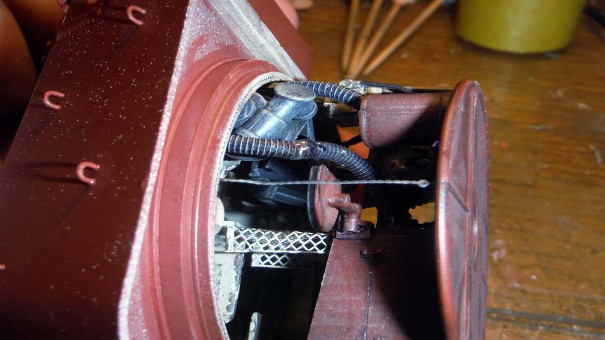
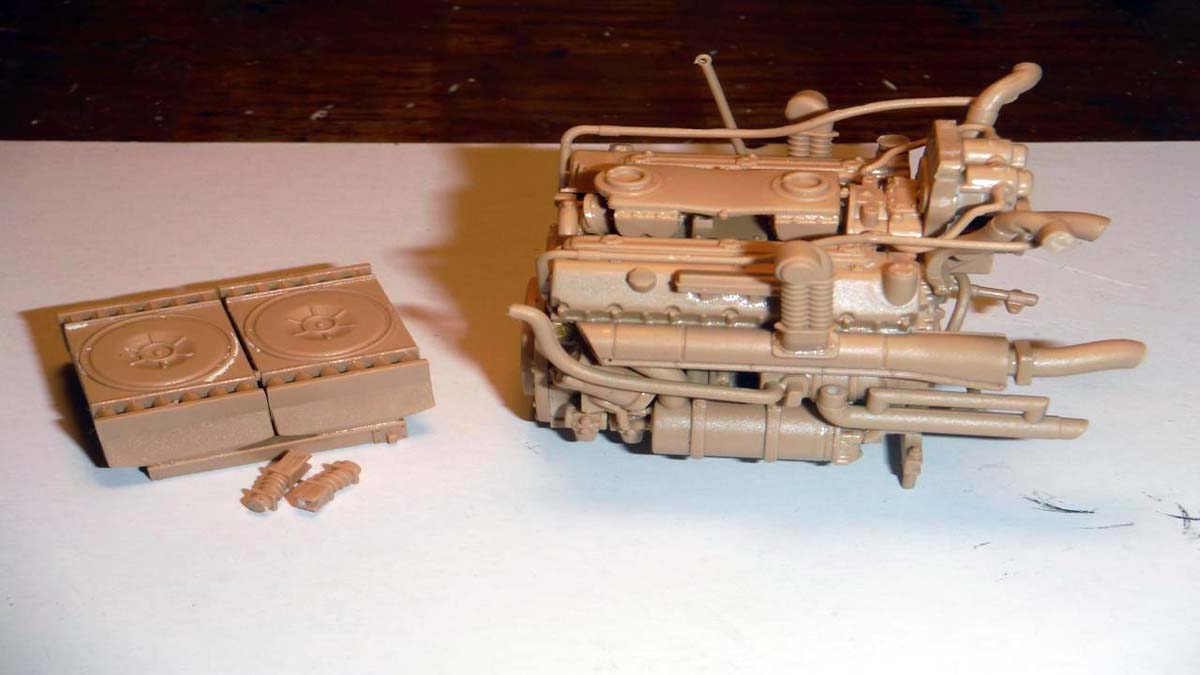
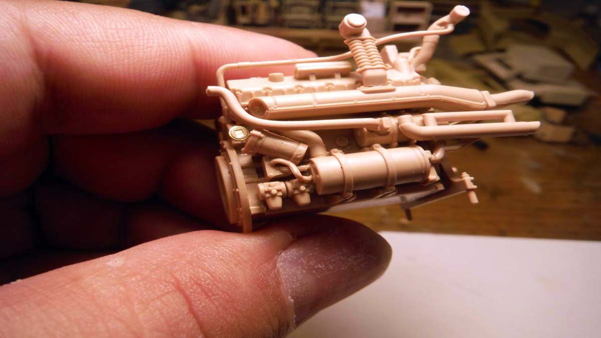
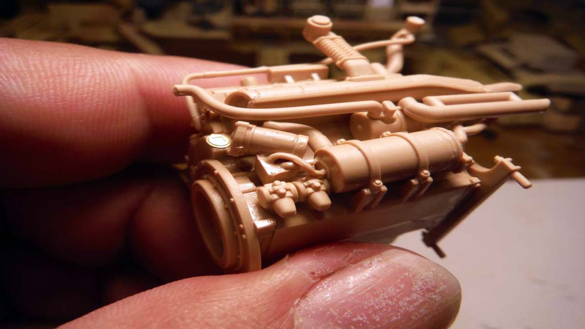
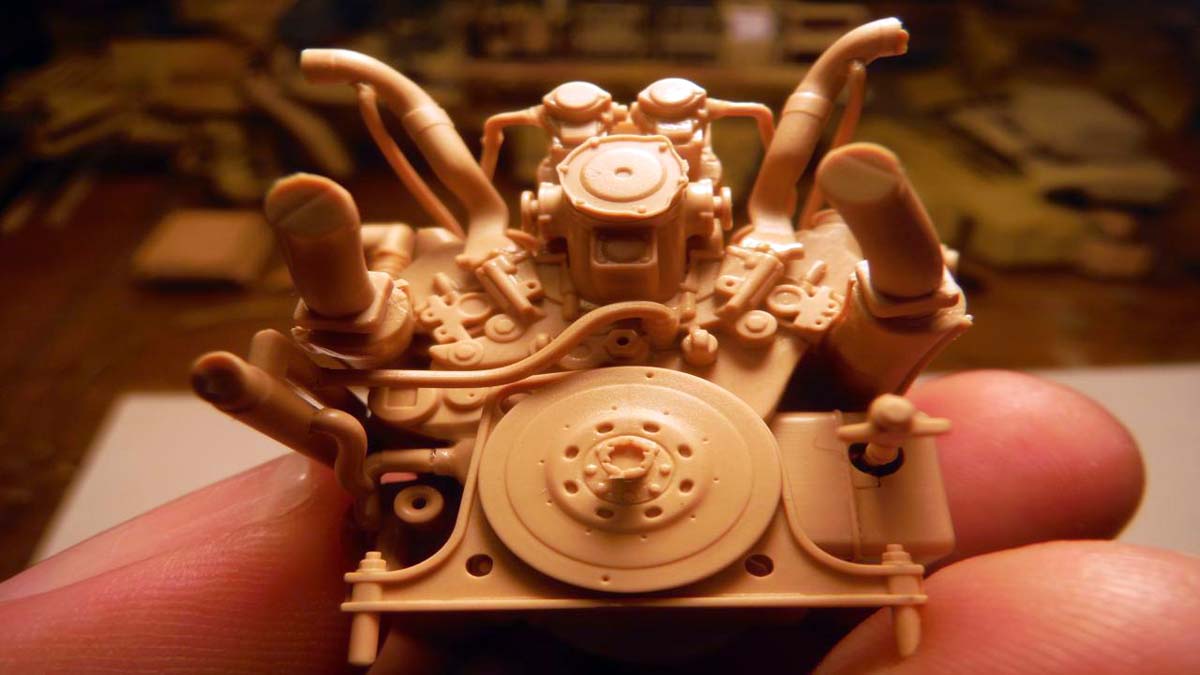
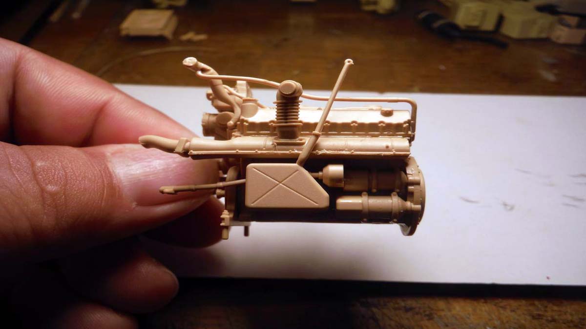
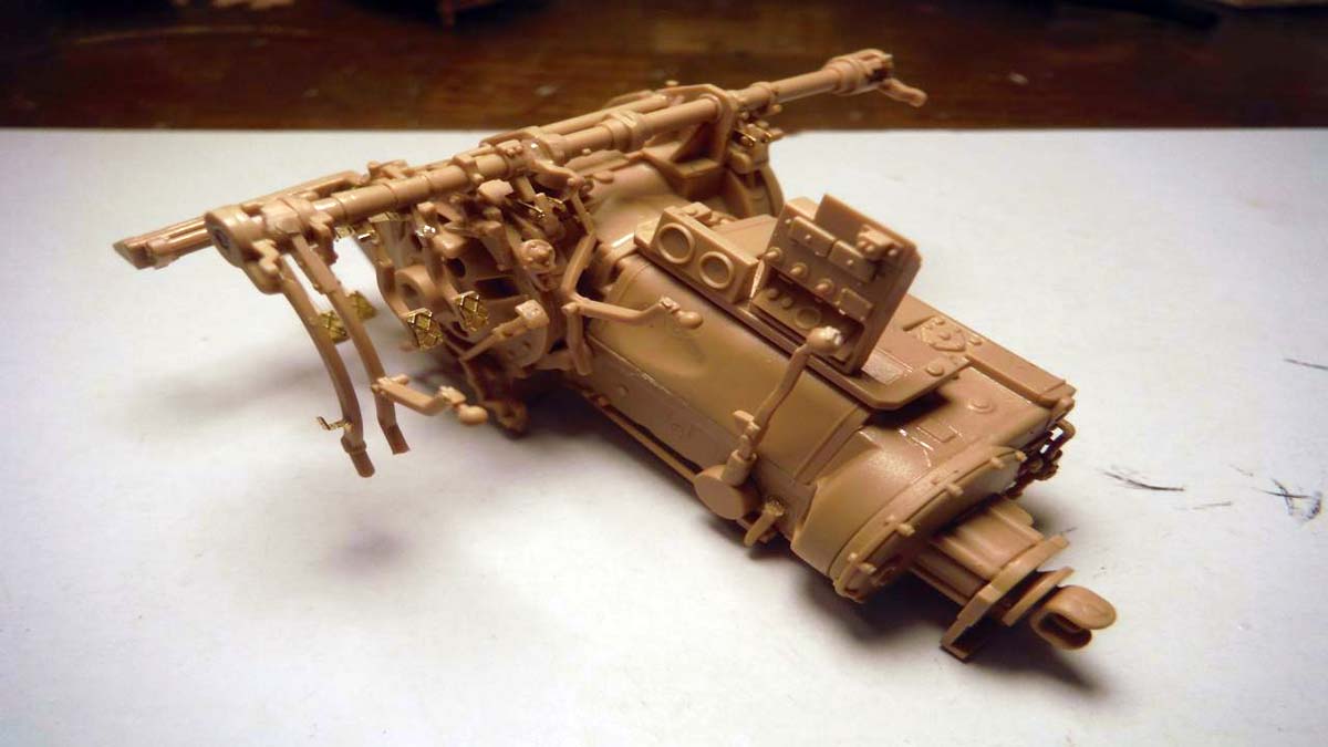
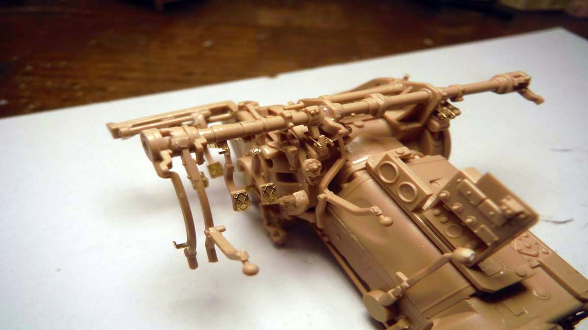
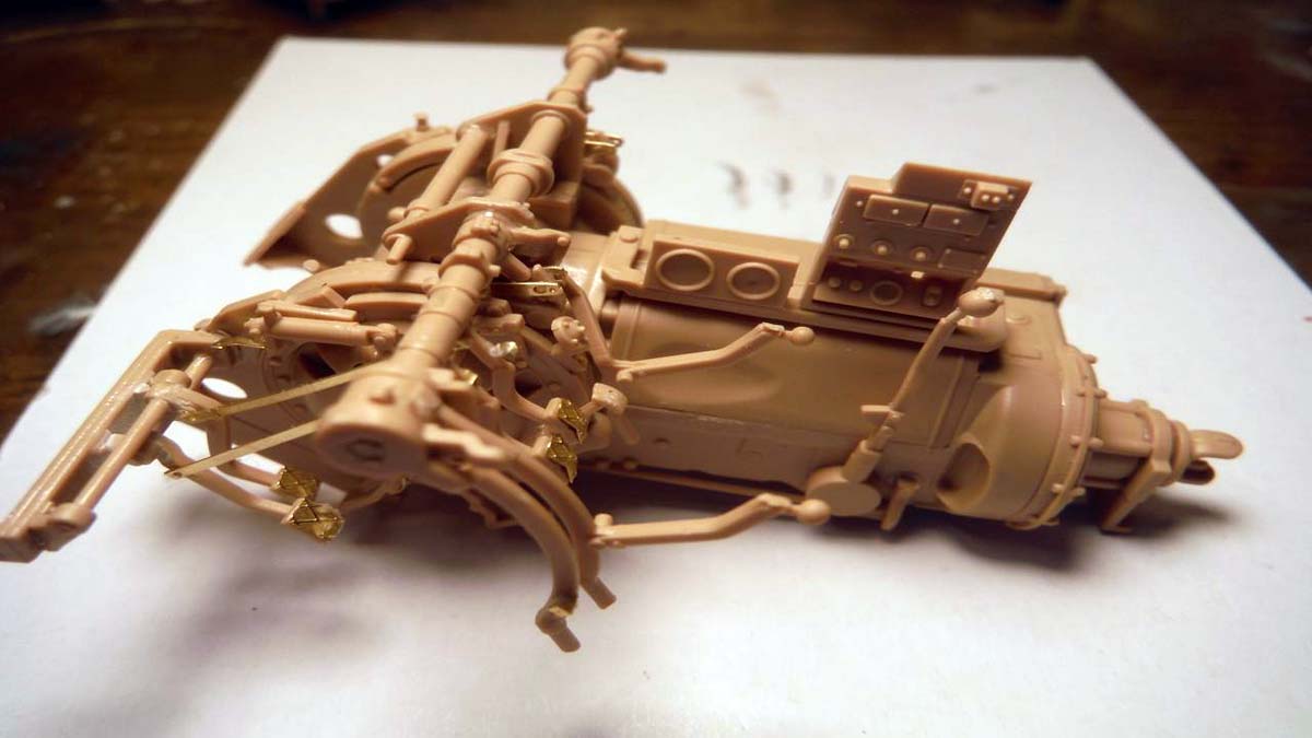
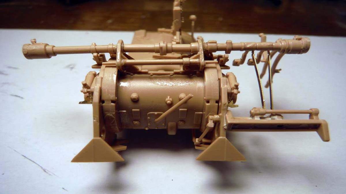
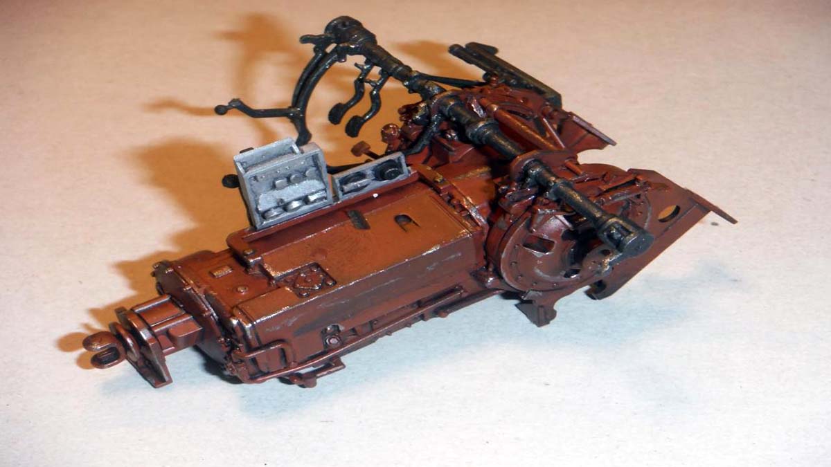
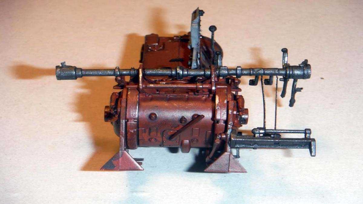
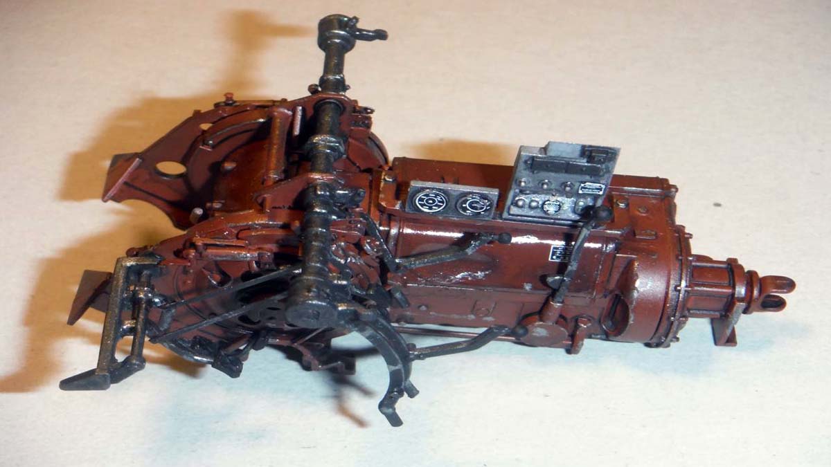
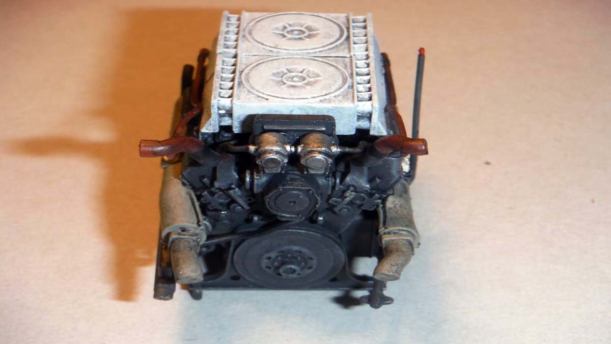
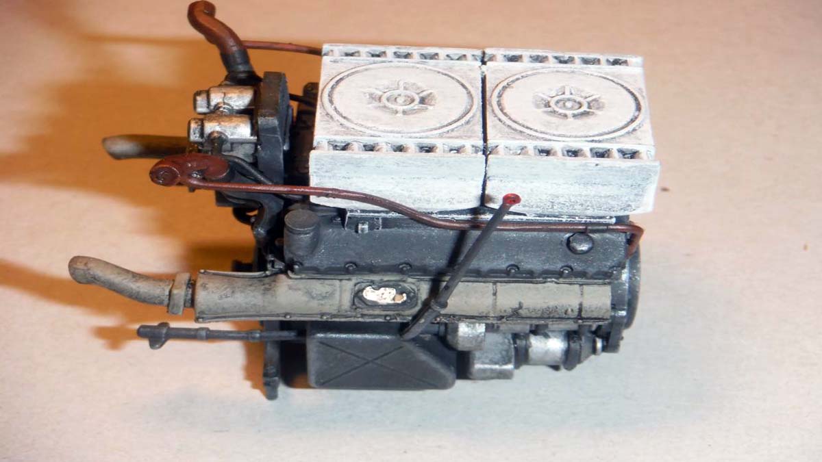
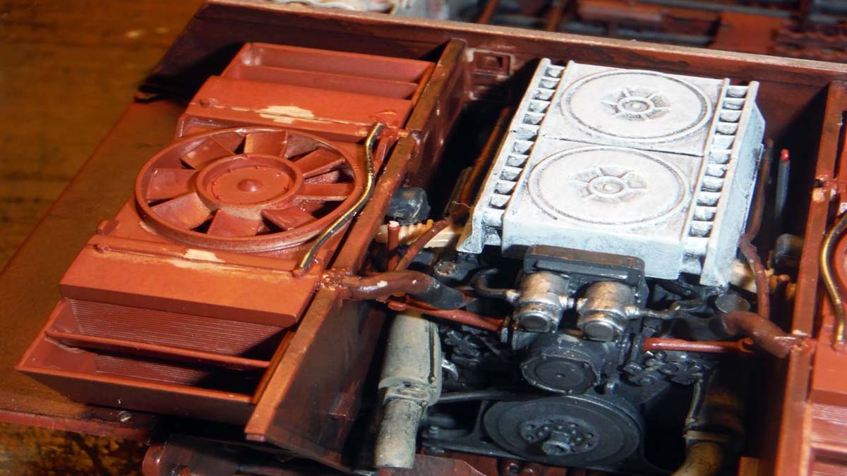
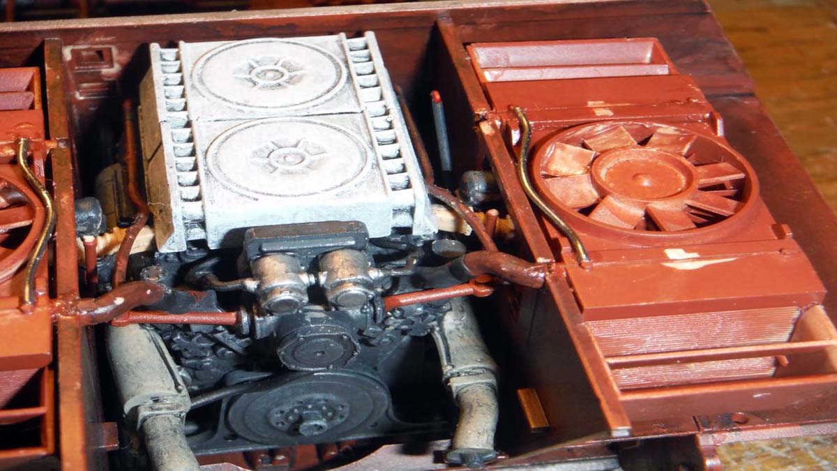
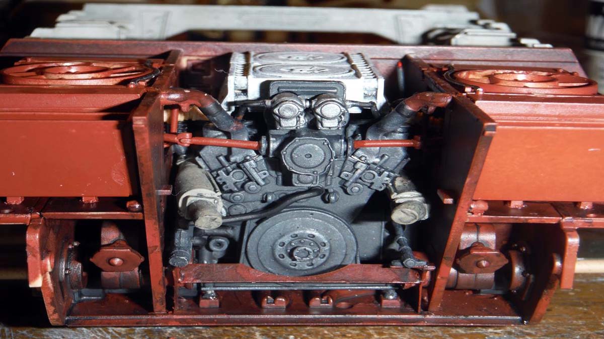
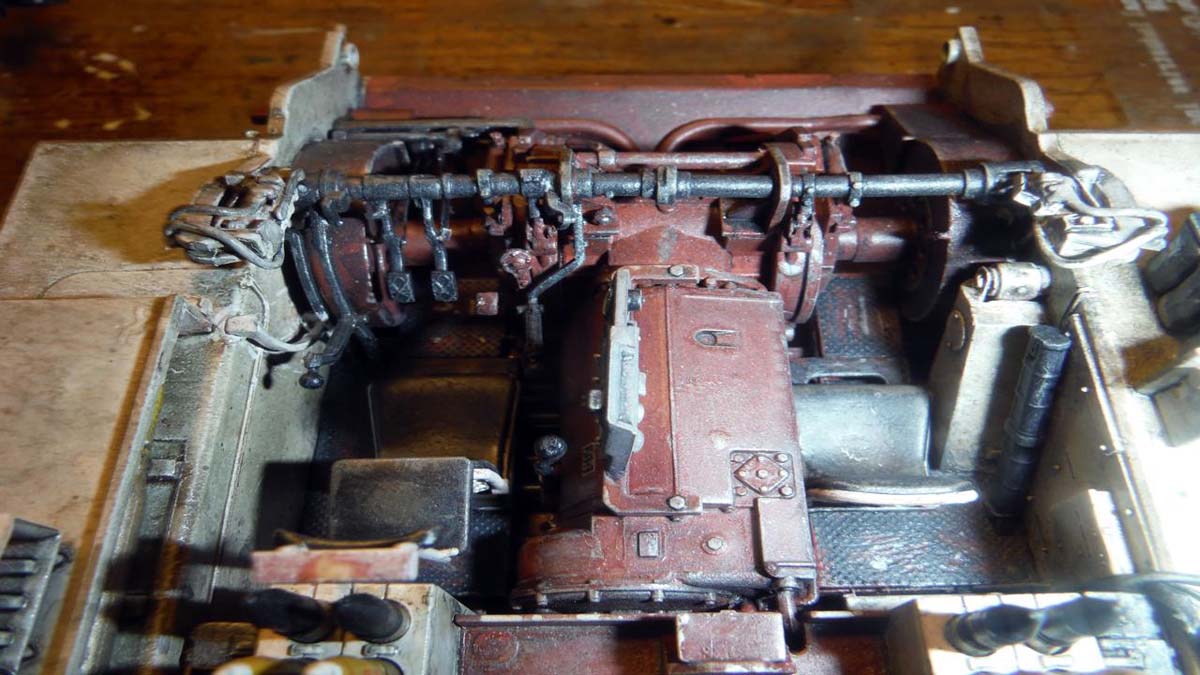
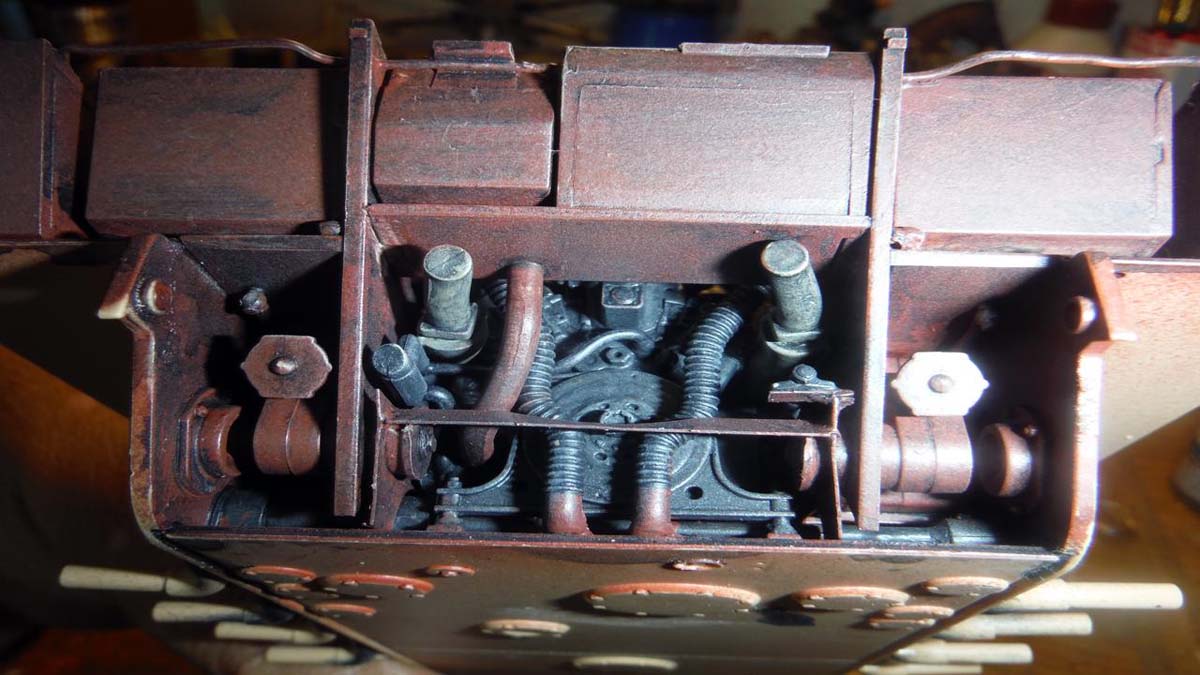
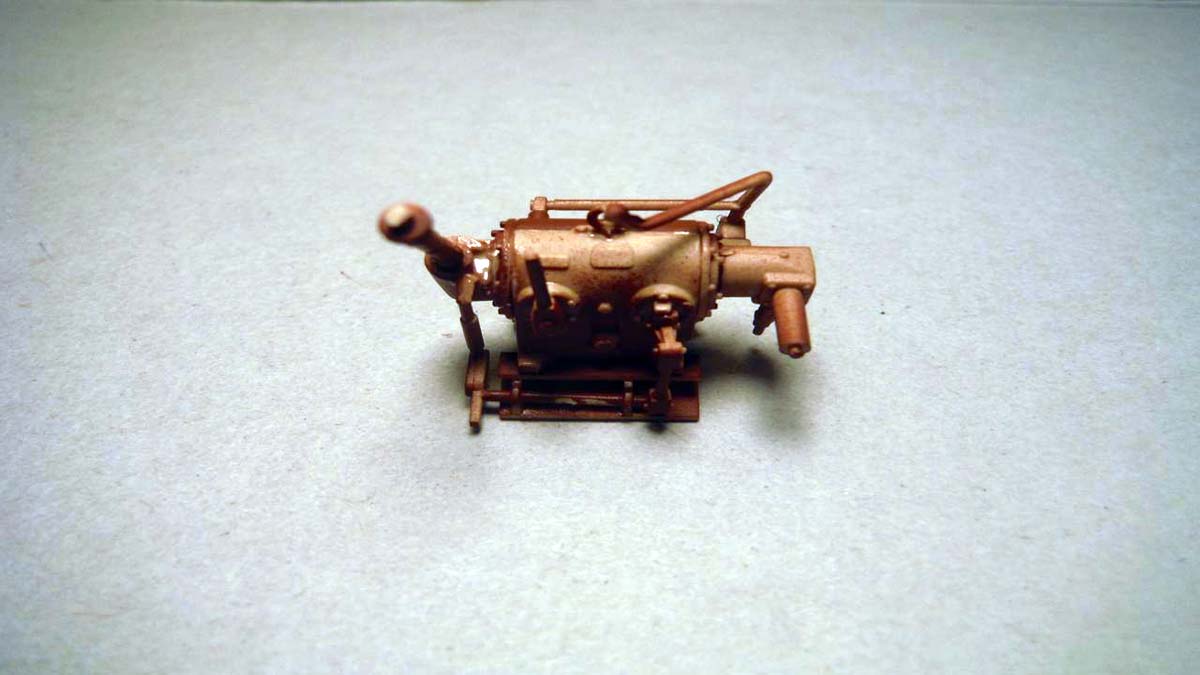
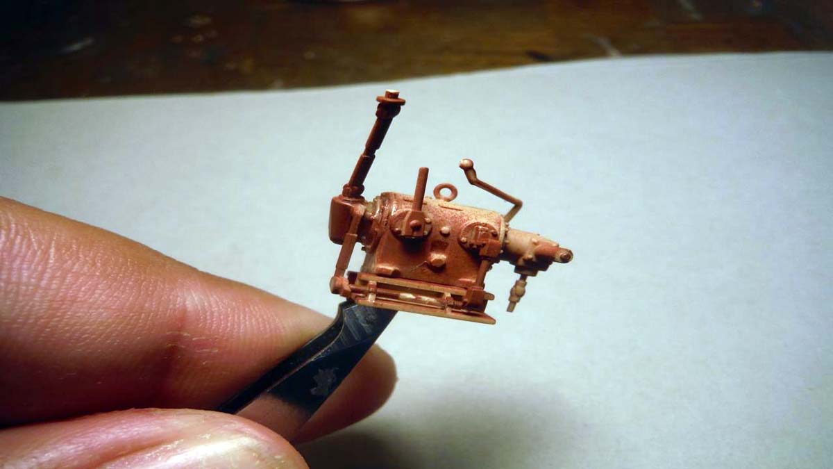
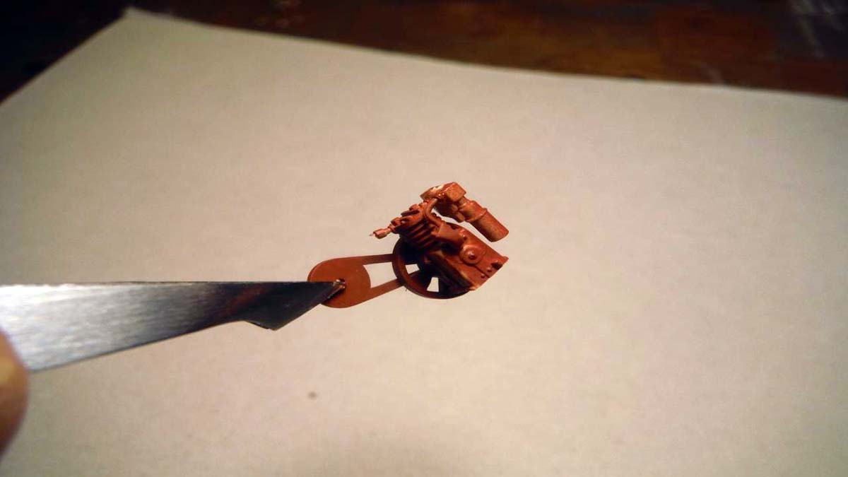
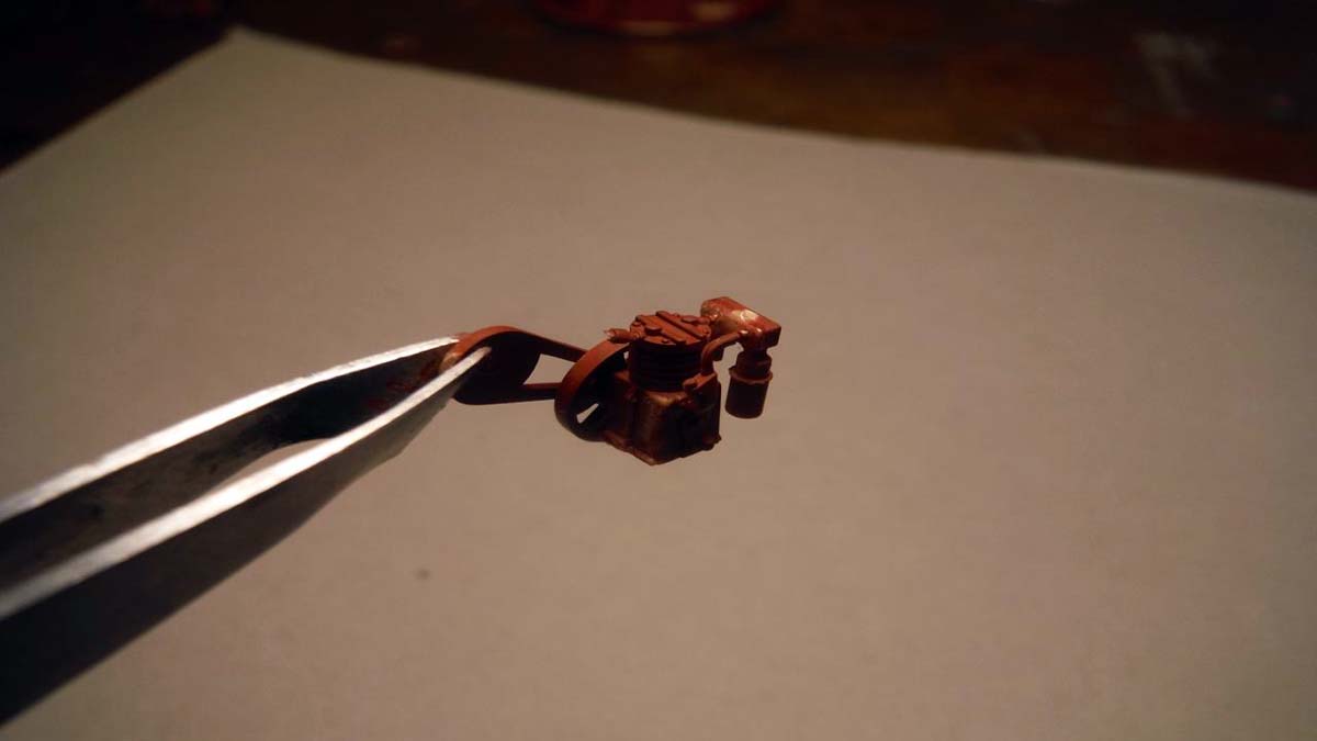
Step 53 starts the construction for the engine. The engine could be packaged as a model itself with all the parts that make it up. BE VERY CAREFUL WITH THE CARPET MONSTER during the construction because there are number of small parts. Also take care when removing the hoses from the trees, they are fragile, but a sharp X-Acto knife will make it easier to remove. All of the parts went together well and no putty was needed because all of the seams were in natural places and/or not noticeable. A couple of notes I managed to find out during construction. In step 55, attach the completed muffler (J48, K64, K65) before you attach parts J50, J85 and J74 to prevent breaking the dip stick. Also, in this step, leave off the hose, part K30, until Step 58. That way it will align better with part J73 in Step 58. In Step 59, make sure the completed air filters are going the same way when attached to K69 and K70 that way they lock down to K31. Also make sure K69 and K70 are in the right direction as compared to the top of the engine and part K31. Other than small pieces that can be easily lost, the engine construction went without any problems. Some seem lines on the hoses need to be cleaned up, other than that, the engine is done and ready for paint.
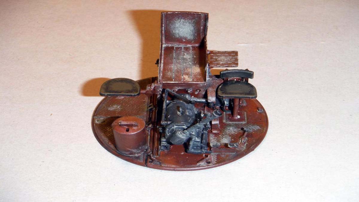
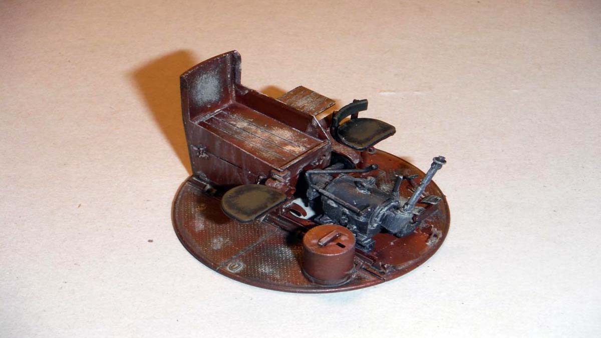
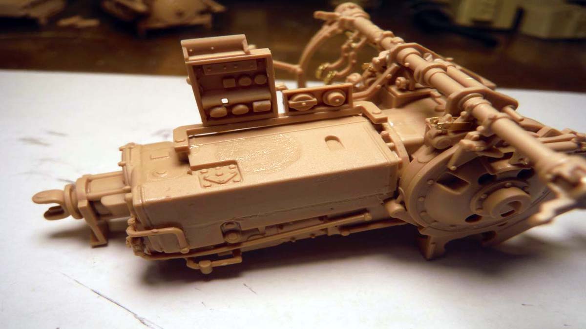
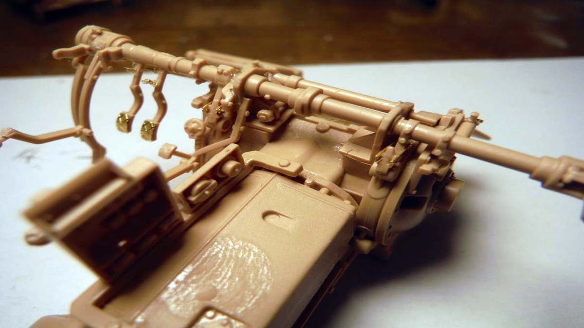
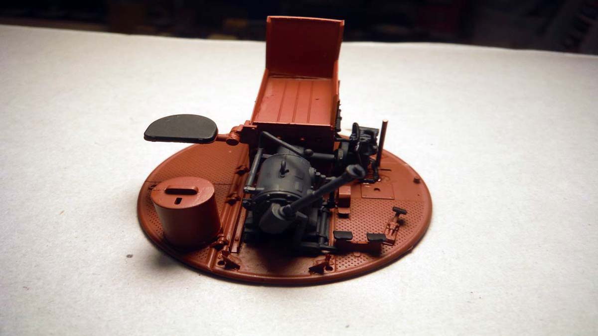
Transmission
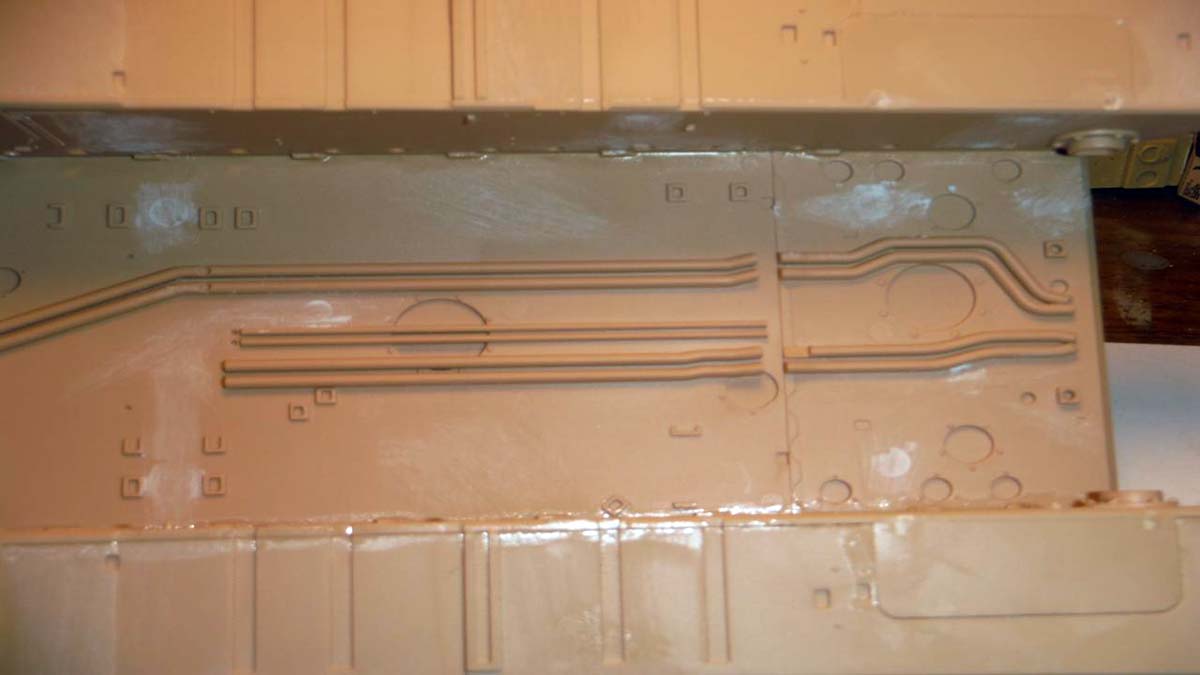
The transmission consists of steps 36 to 41 starting with the drive handles and pedals. A few of the parts are very fragile and small. Take care in step 36, sub step C14 and C15 so you don not break any of the handles and pedals. I didn't do this, but it might be a good idea to place some tape under the photo etch while you cut the parts off, there are some very small and easily lost parts here. As I said, read the instructions over and over to get a good idea on where to build and what you can skip till another step. After doing it, I found that it would have been easier to glue Step 36, sub step C14 at Step 40 and then glue Step 36, sub step C13 and C14 after so that you can get a straight alignment. On sub step C17, the instructions do not say to add photo etch part Y92 to pedal part D83. The rest of the transmission went together well and no putty was needed. All of the seams were in naturally hidden places. Also decal 19 and 22 are switched on the instructions in step 39. Most modelers will be satisfied with the build up to here, but the one who wants to go far and beyond could add the missing hydraulic lines as you can see in these pictures from the internet.
Side Note
Let me say this first, this kit is not for the faint of heart. You really have to sit down and read through the directions several times to get an idea how you want to tackle the build. First and for most, after building the engine and transmission, I found it very easy to just paint all the sprues, well at least 80% of the sprues, especially the ones with all the interior parts. Then build and touch up, build and touch up.
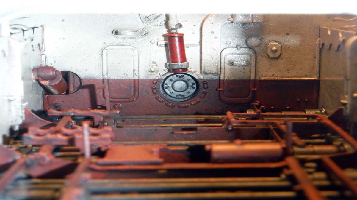
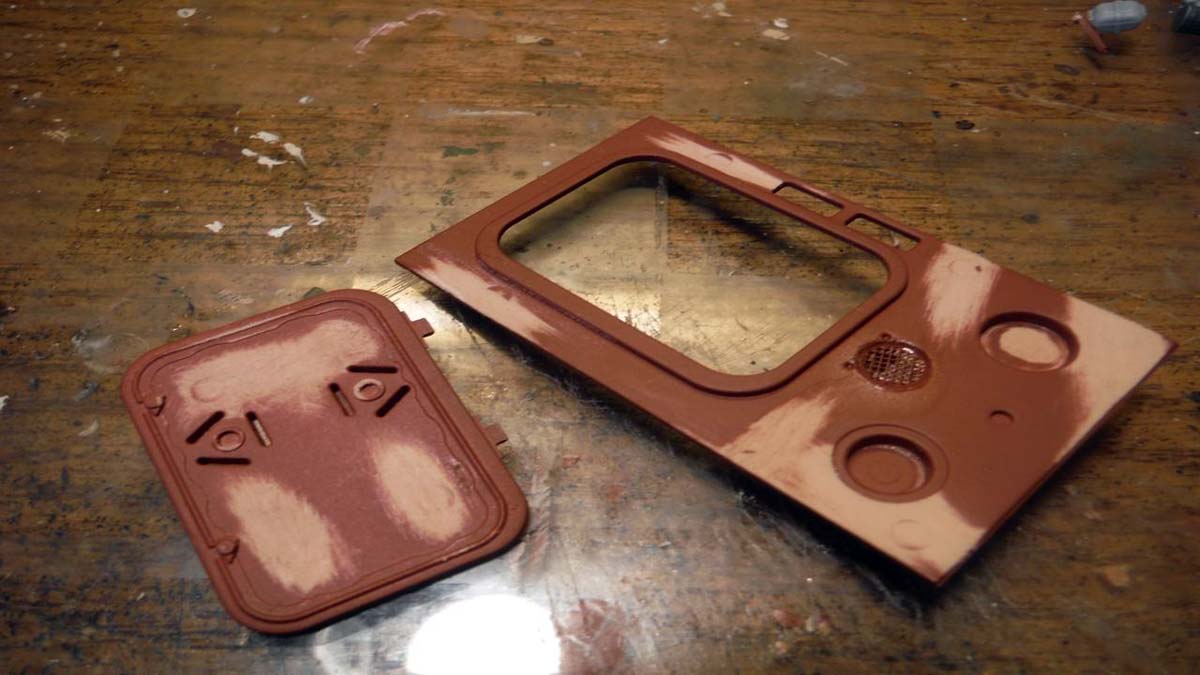
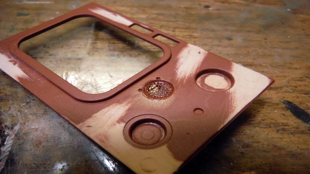
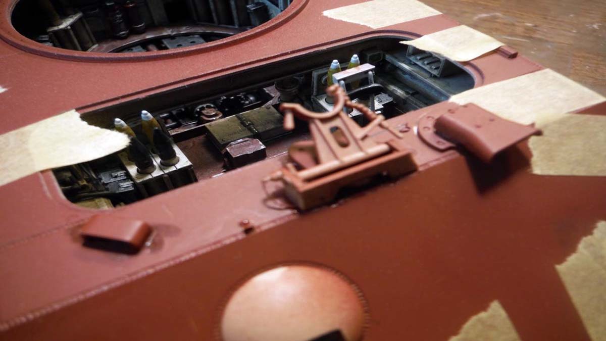
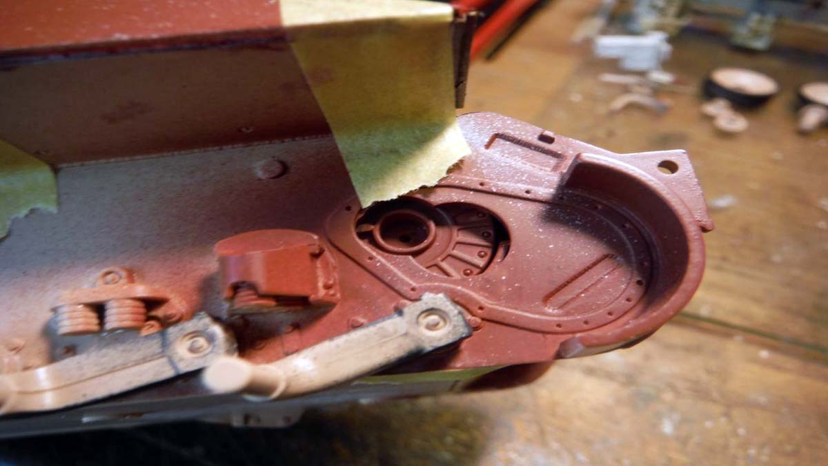
I am not going with the interior color call out in the kit instructions. From what I've read and seen, most of the interior is the Red Oxide, to include engine bay, and the middle of the hull and turret interior is Cremeweis. Tamiya Red Oxide Surface Primer is a very damn good paint. It is Lacquer based and very strong on the parts once dried. I even sprayed the photo etch and the photo etch takes a beating before any of the Primer attempts to come off. I also found that a 50-50 mix of Vallejo 940 Saddle Brown and 957 Flat Red is a very close match to the Tamiya Red Oxide for touch ups. The color Cremeweis was made from mixing 90% Tamiya X-2 Gloss White and 10% X-57 Buff.
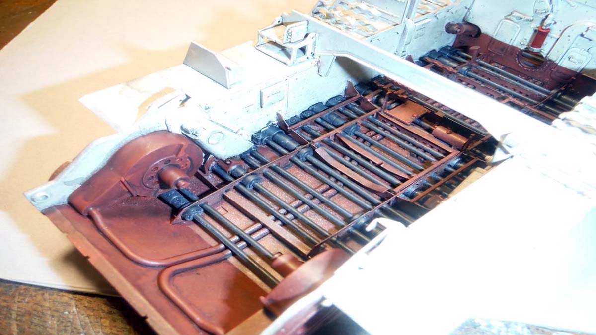
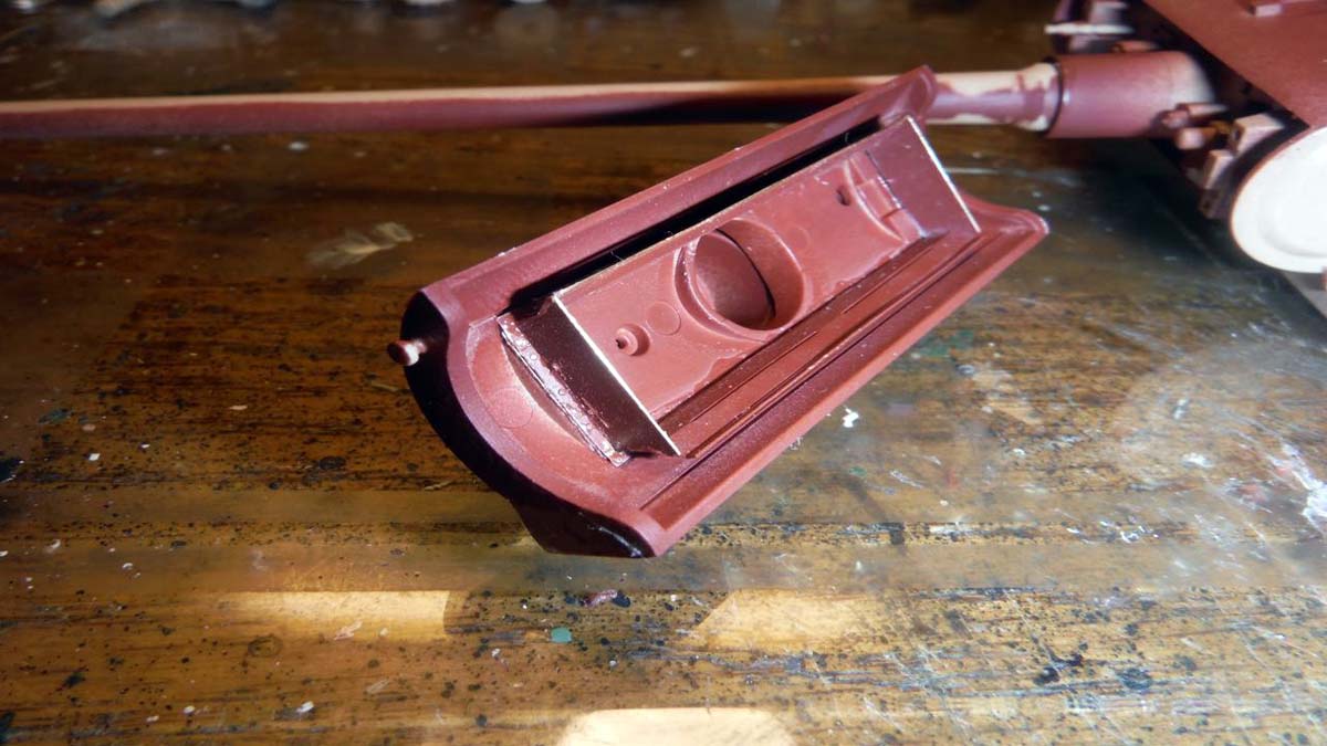
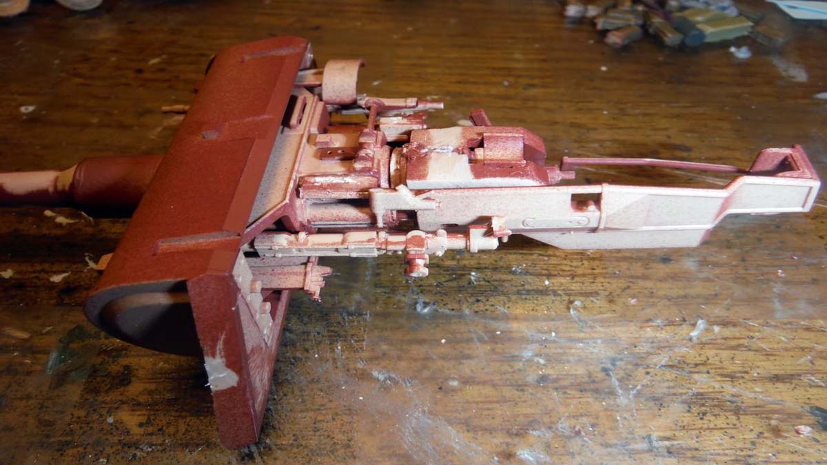
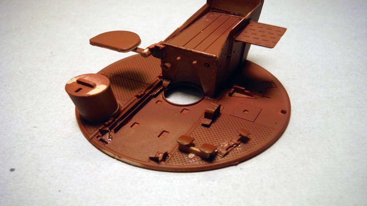
Hull
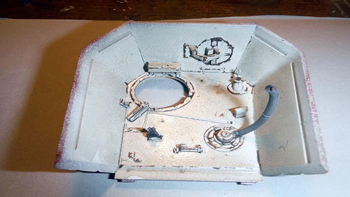
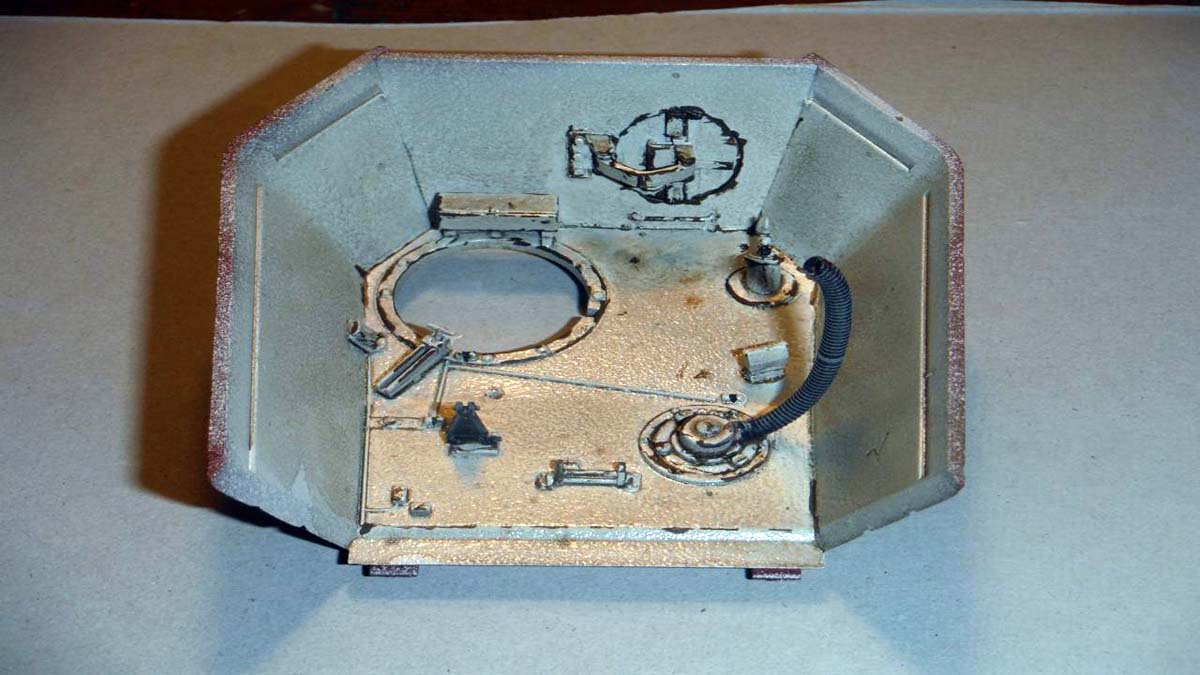
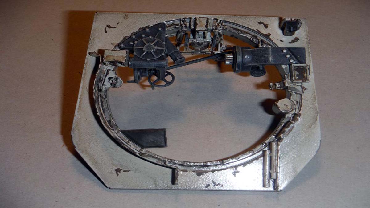
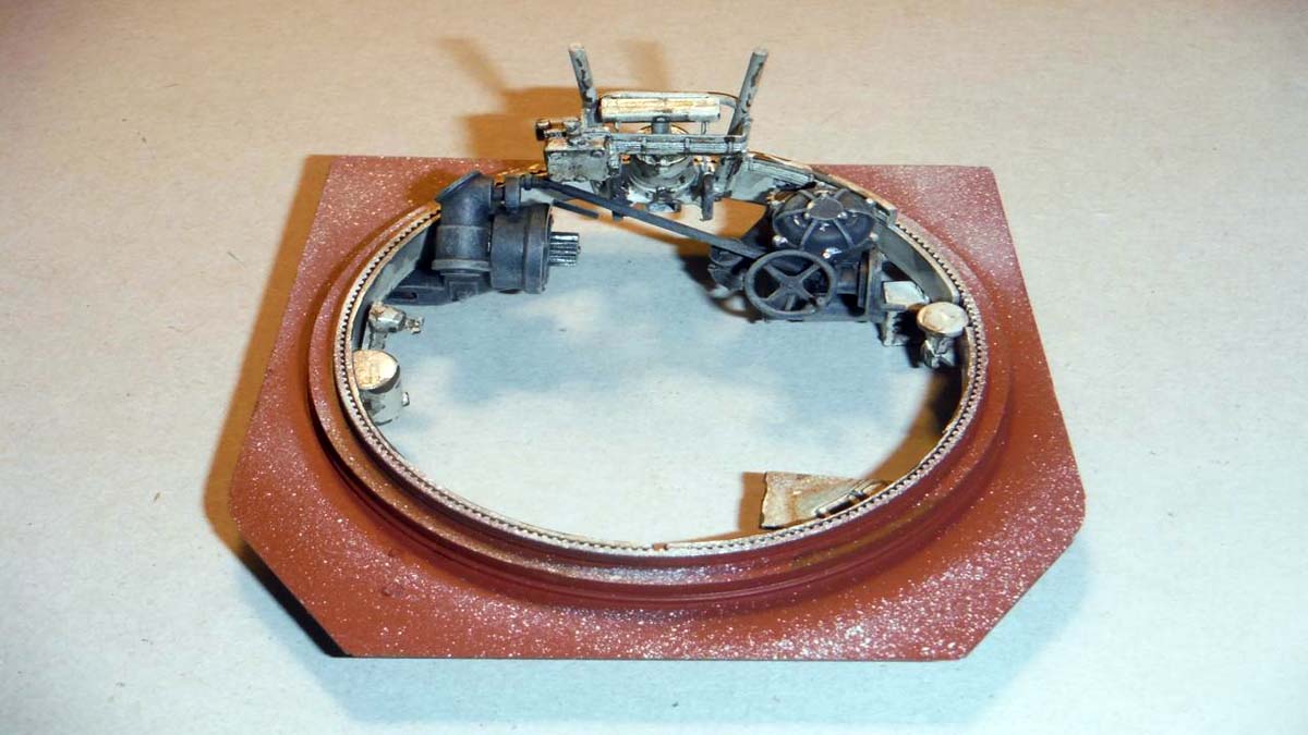
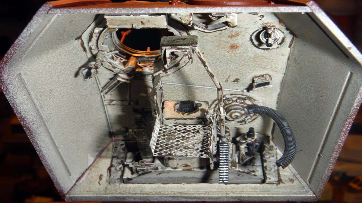
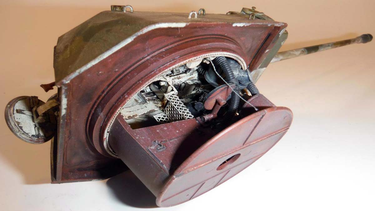
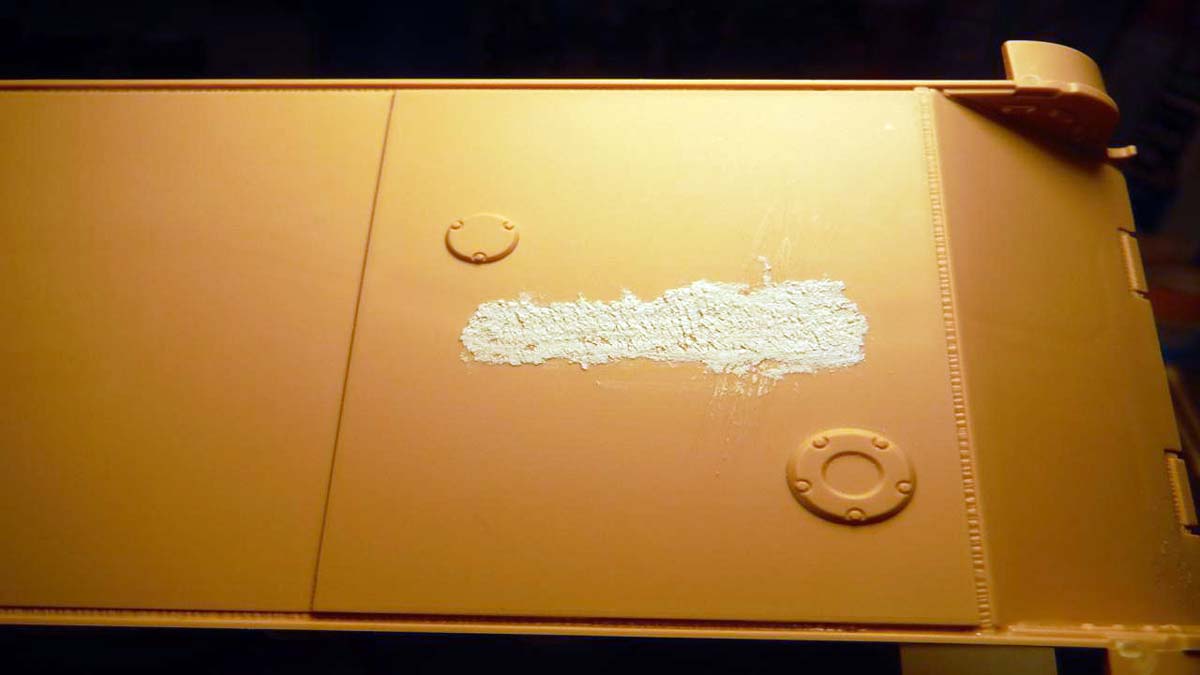
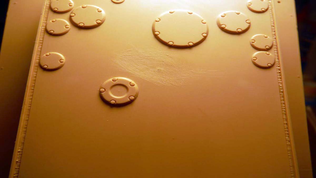
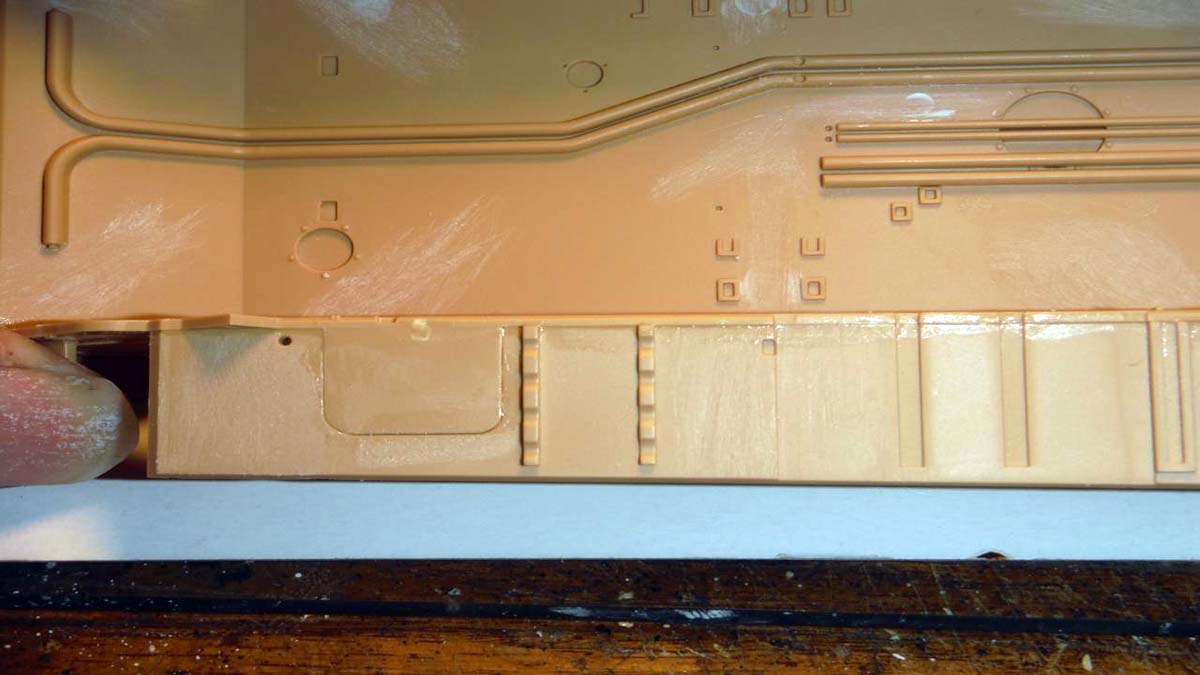
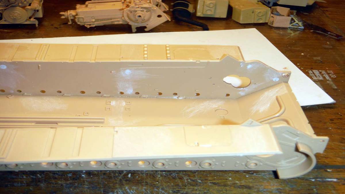
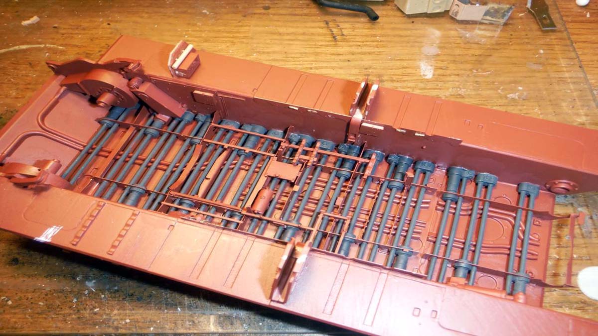
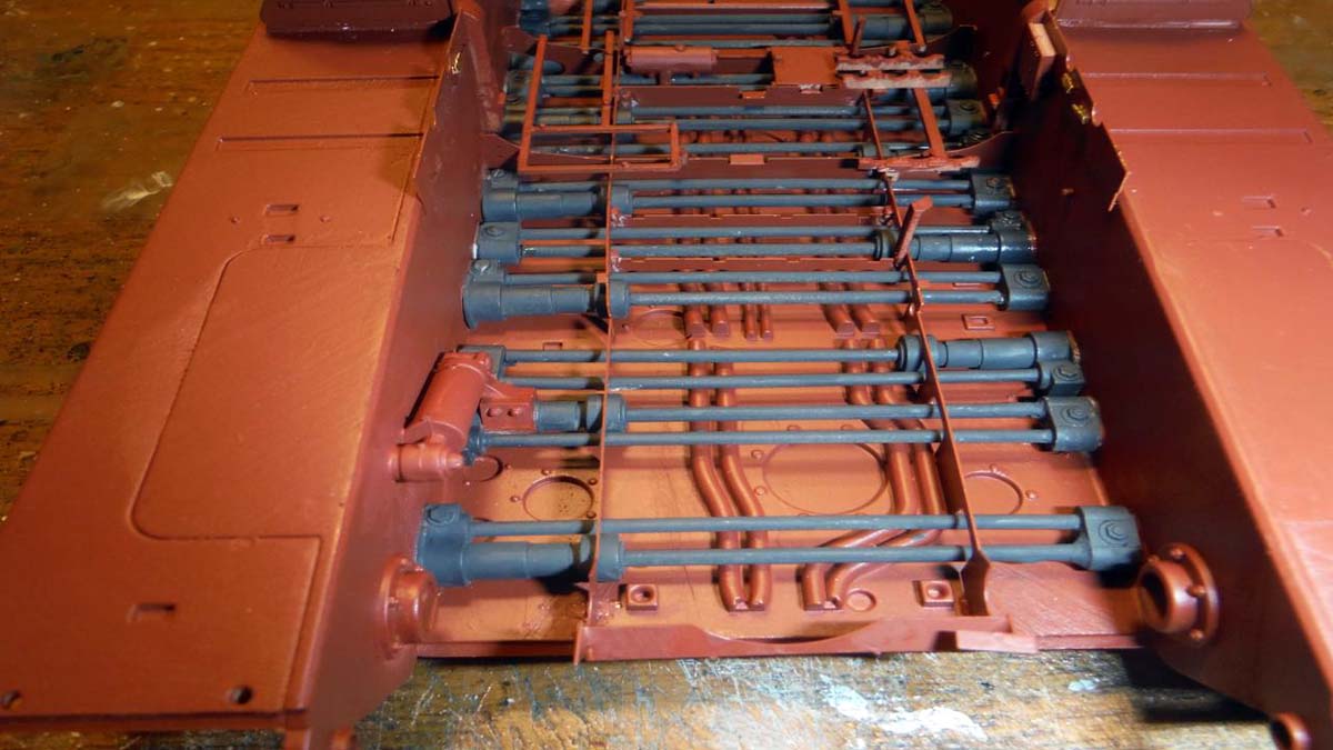
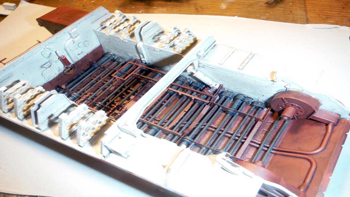
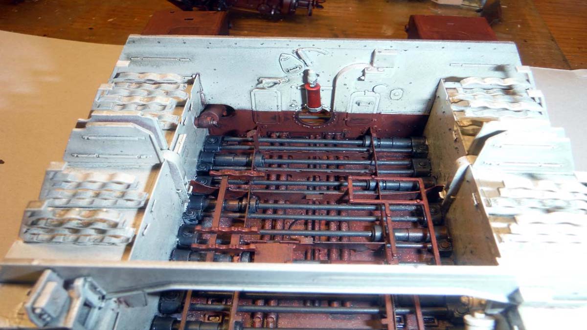
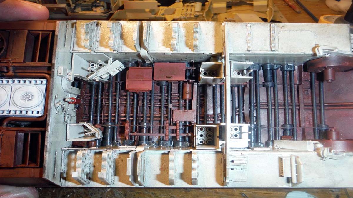
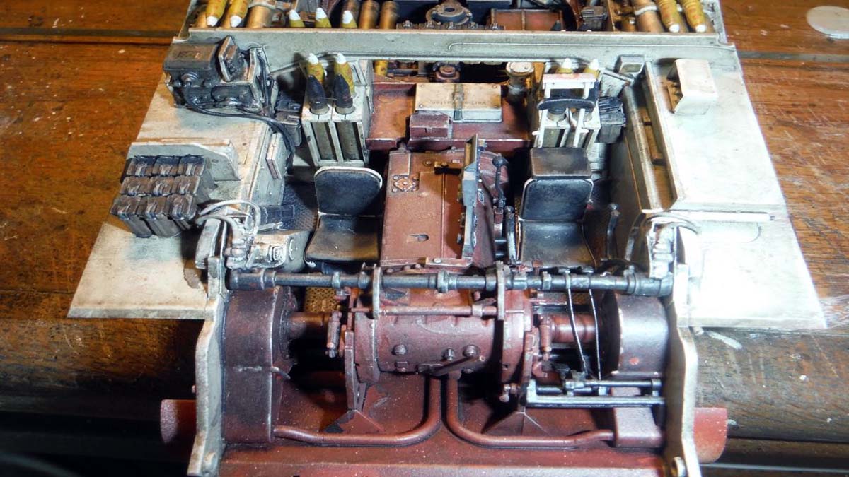
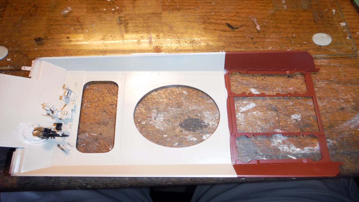
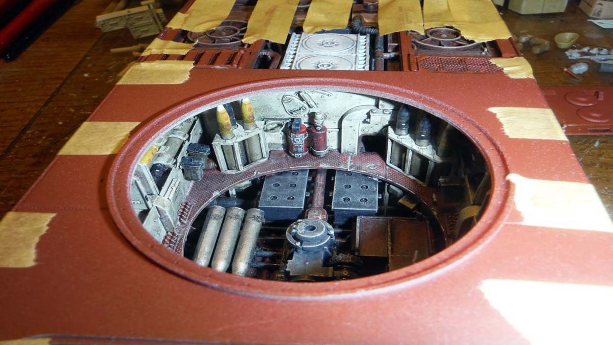
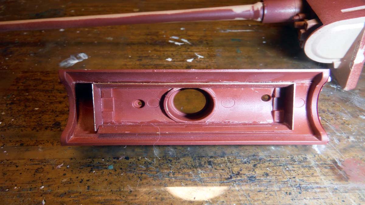
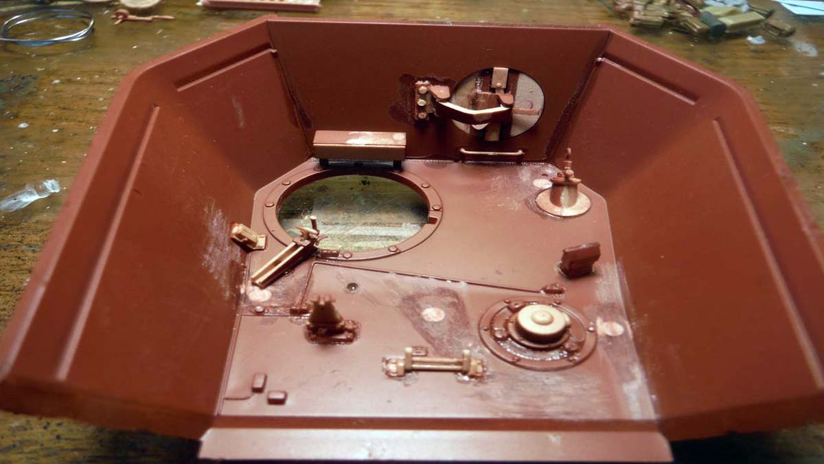
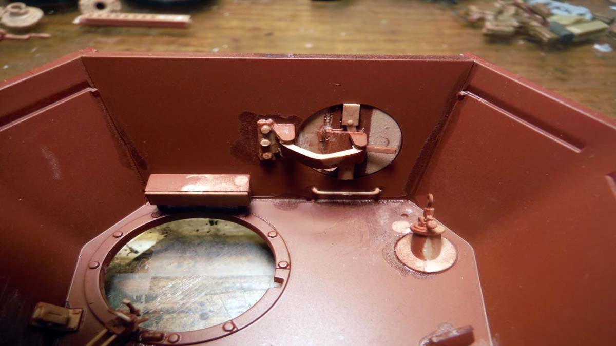
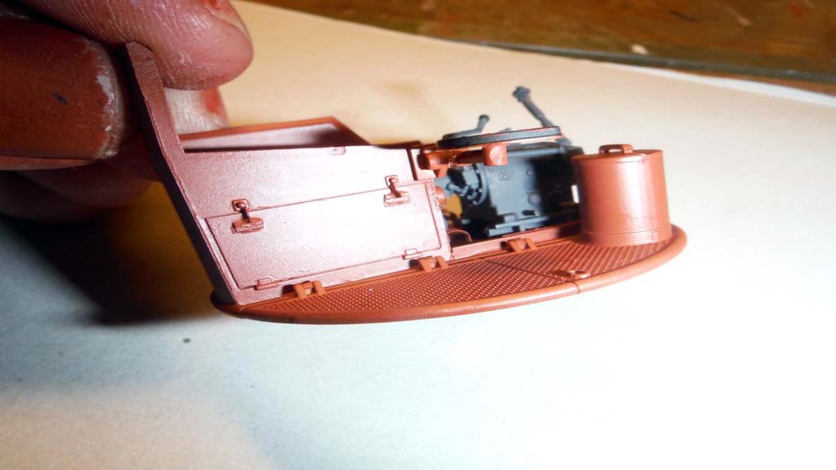
Since I had the engine and transmission done, I decided to go on to the lower hull interior. I started with filling and sanding ejector pin marks and such. Like I said above, because of the complexity of the build, I chose to paint a lot of stuff on sprues and/or before assembly. Interior hull was painted Oxide Red and Cremeweis along with the torsion bars being black.
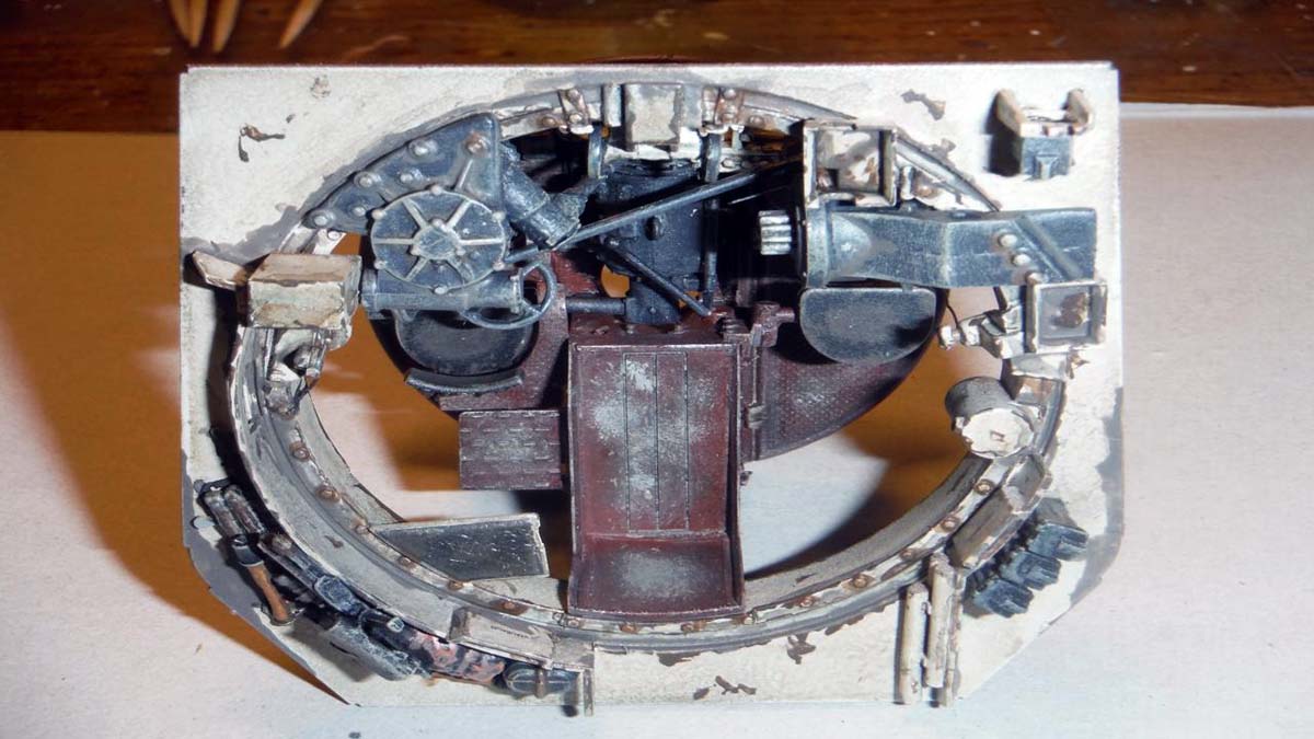
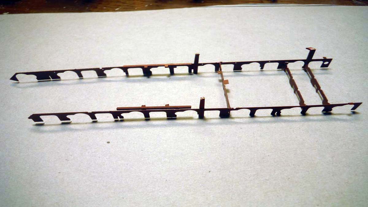
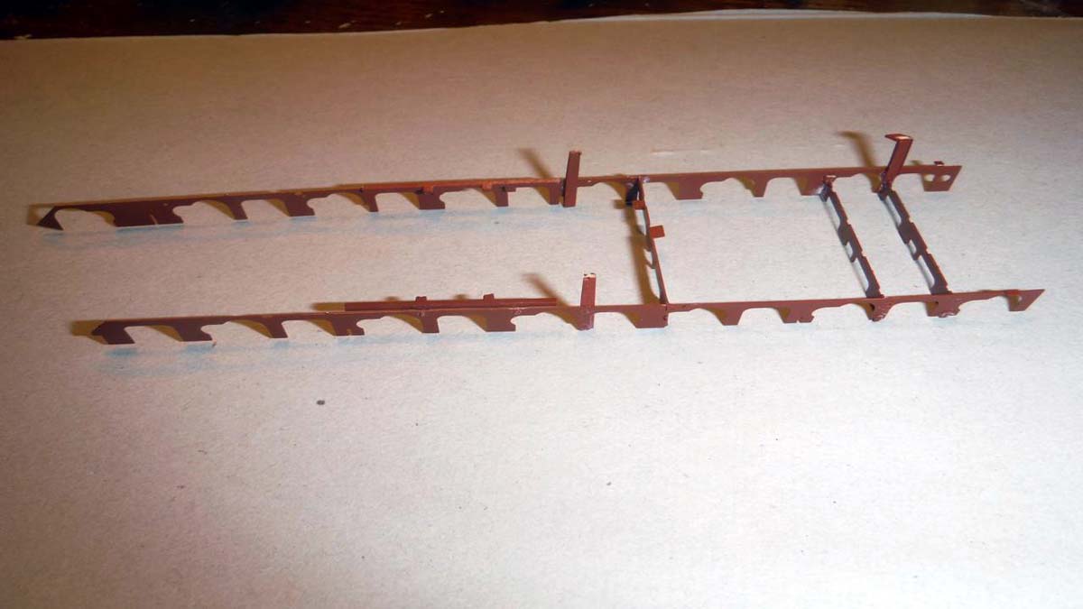
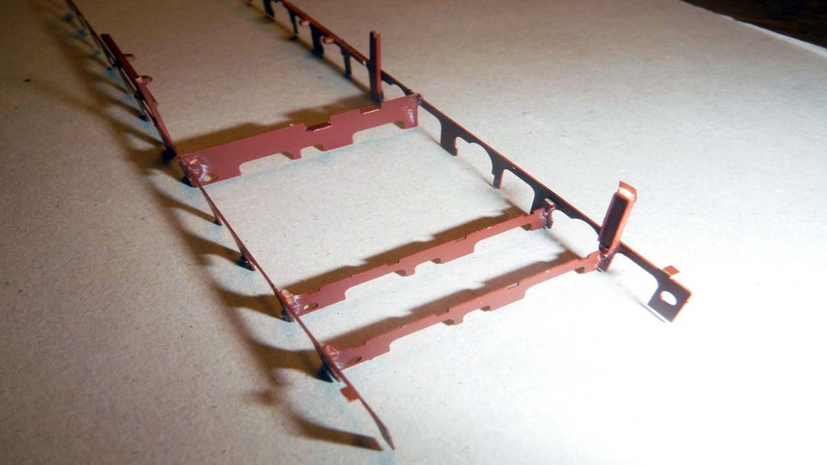
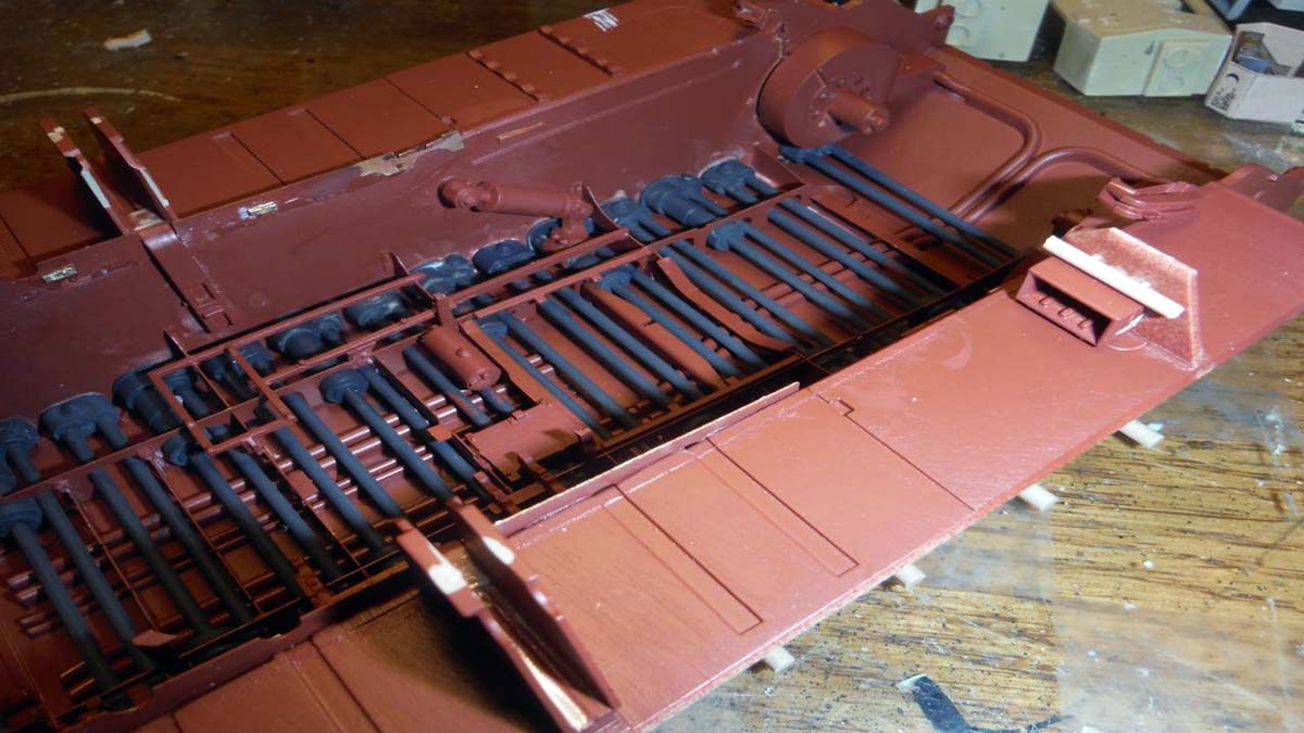
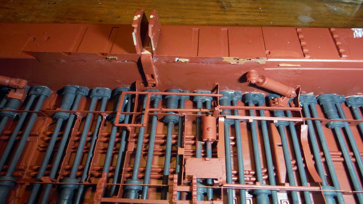
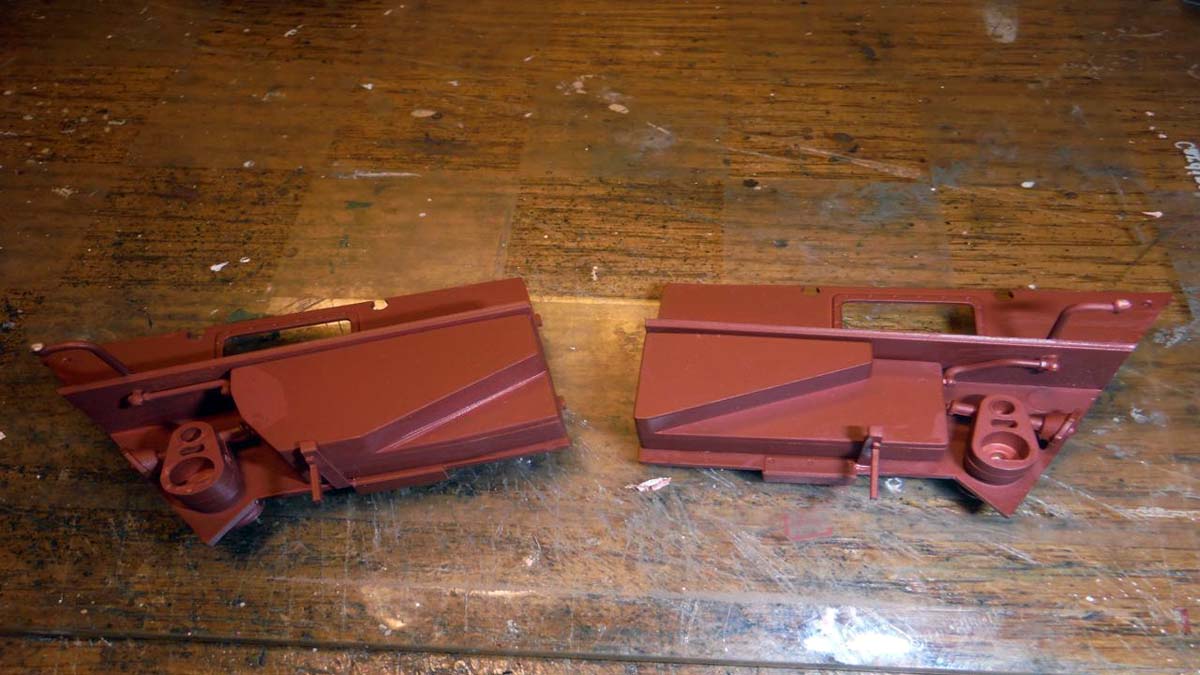
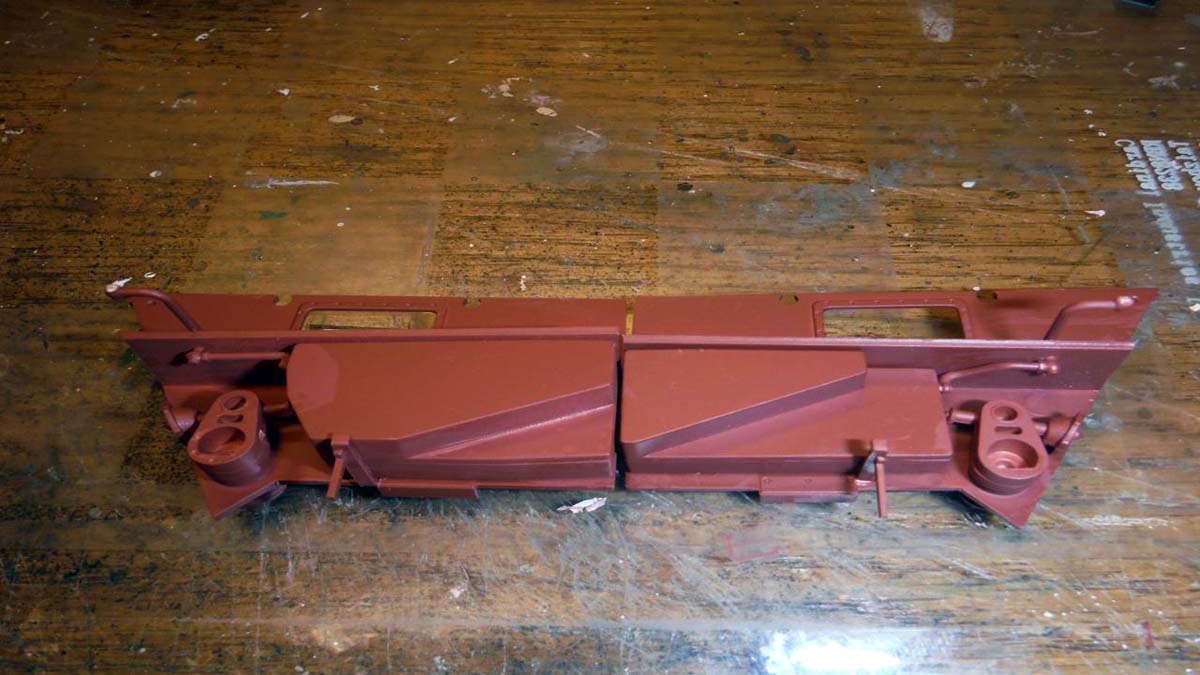
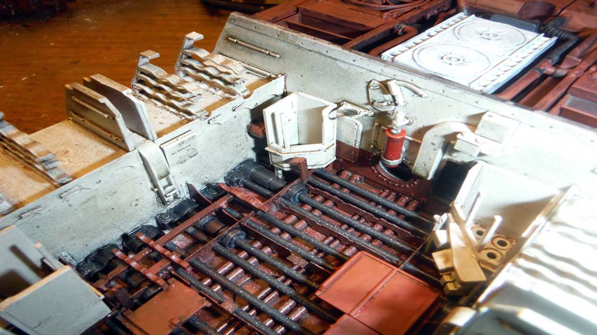
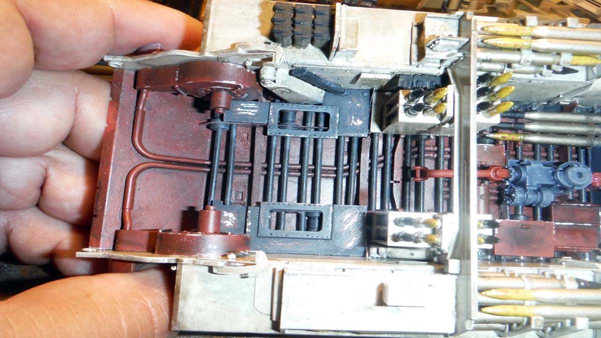
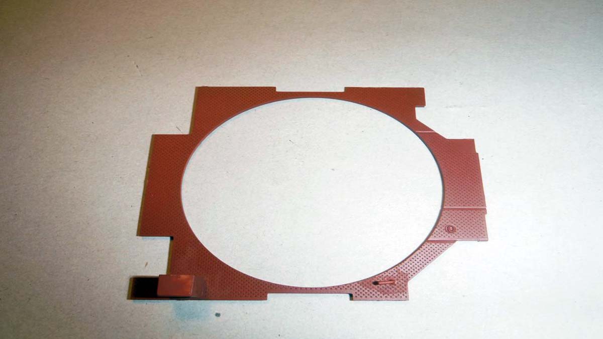
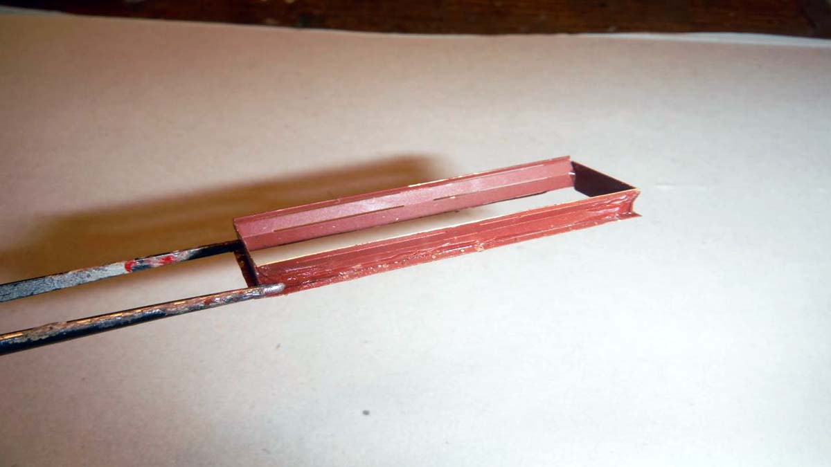
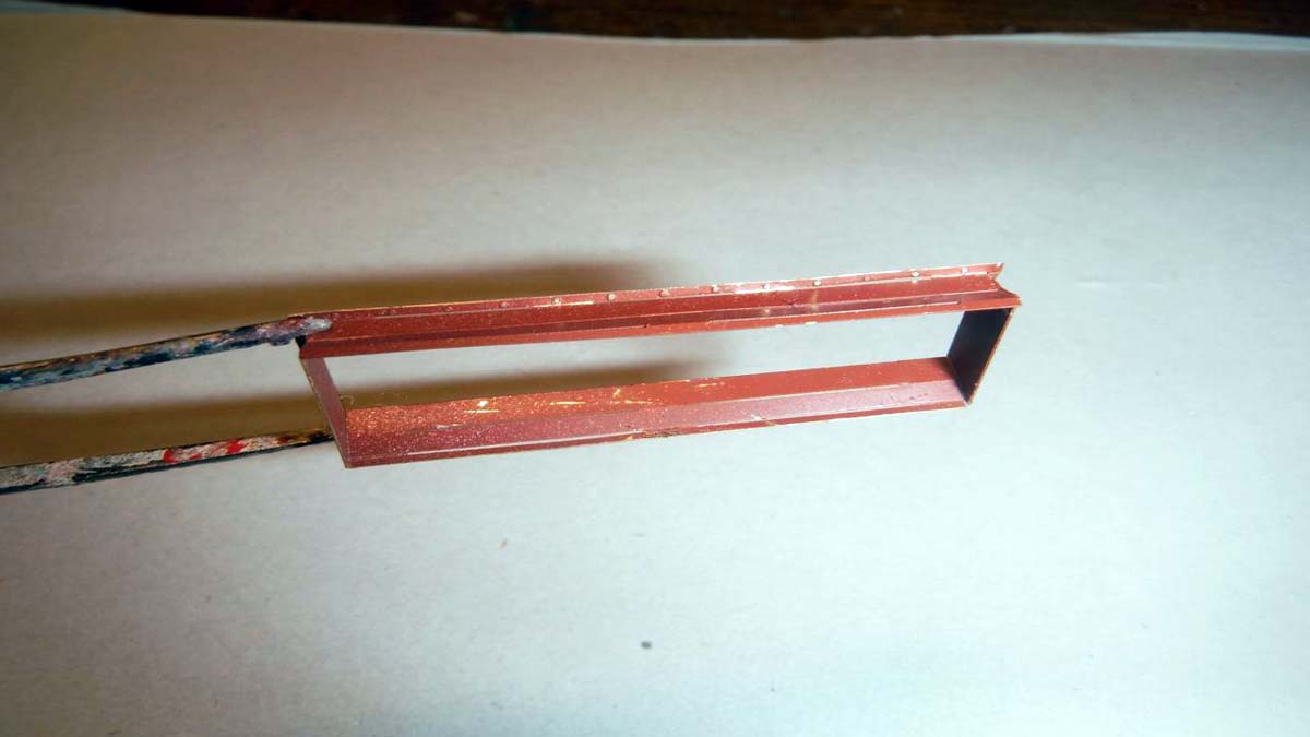
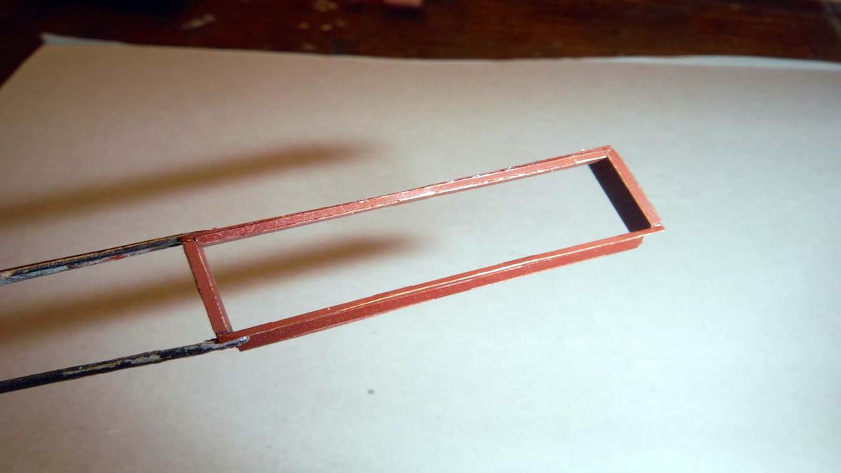
Once the torsion bars where installed, I started on the photo etch frame that went inside the lower hull over the torsion bars. The photo etch frame started in step 30, sub step C7, C8, C9, and continues on in step 32. So, I skipped step 31 till after the frame was all built. I went back to step 31 and installed all the road arms/torsion bars. You can cut a locking pin on each road arm in order for the road arms can move up and down. I chose to just glue the arms stationary. Once the road arms where glued in place and level, I went ahead and installed the whole photo etch frame and its cross beams. Be very patient when you install the cross beams and frame. It might seem to not fit, but with a little forcible help, everything will line up. At this time, I went ahead and jumped to step 51 and 52, the engine side walls.
By now, you can see that this is really a sub-assembly build.
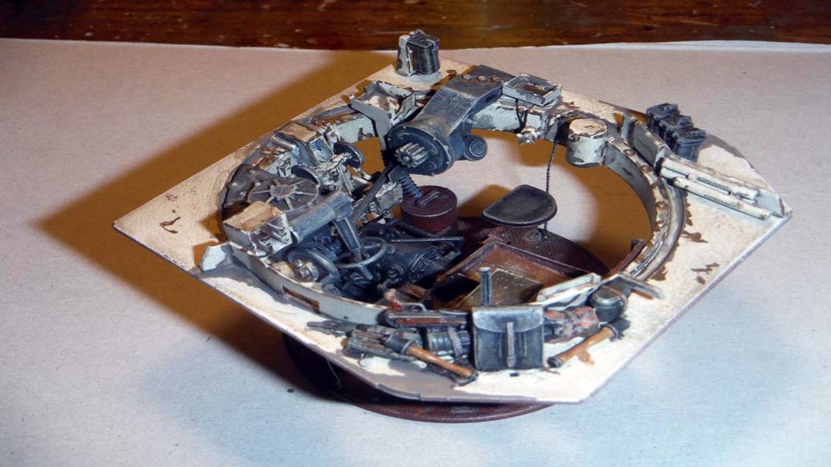
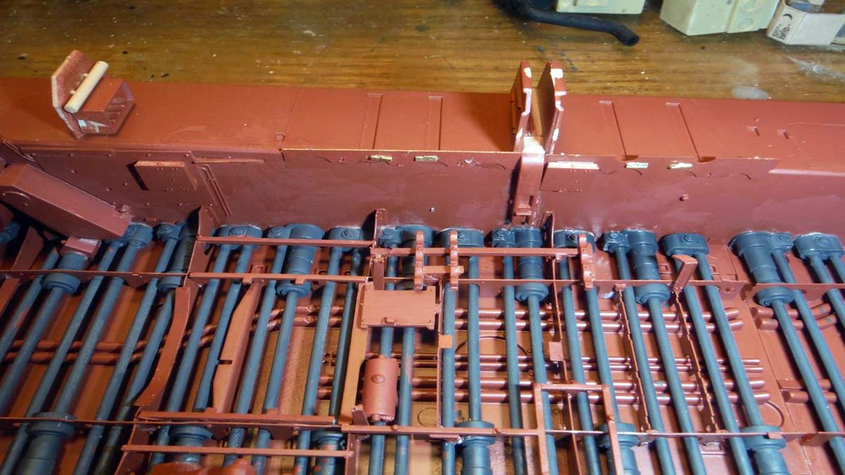
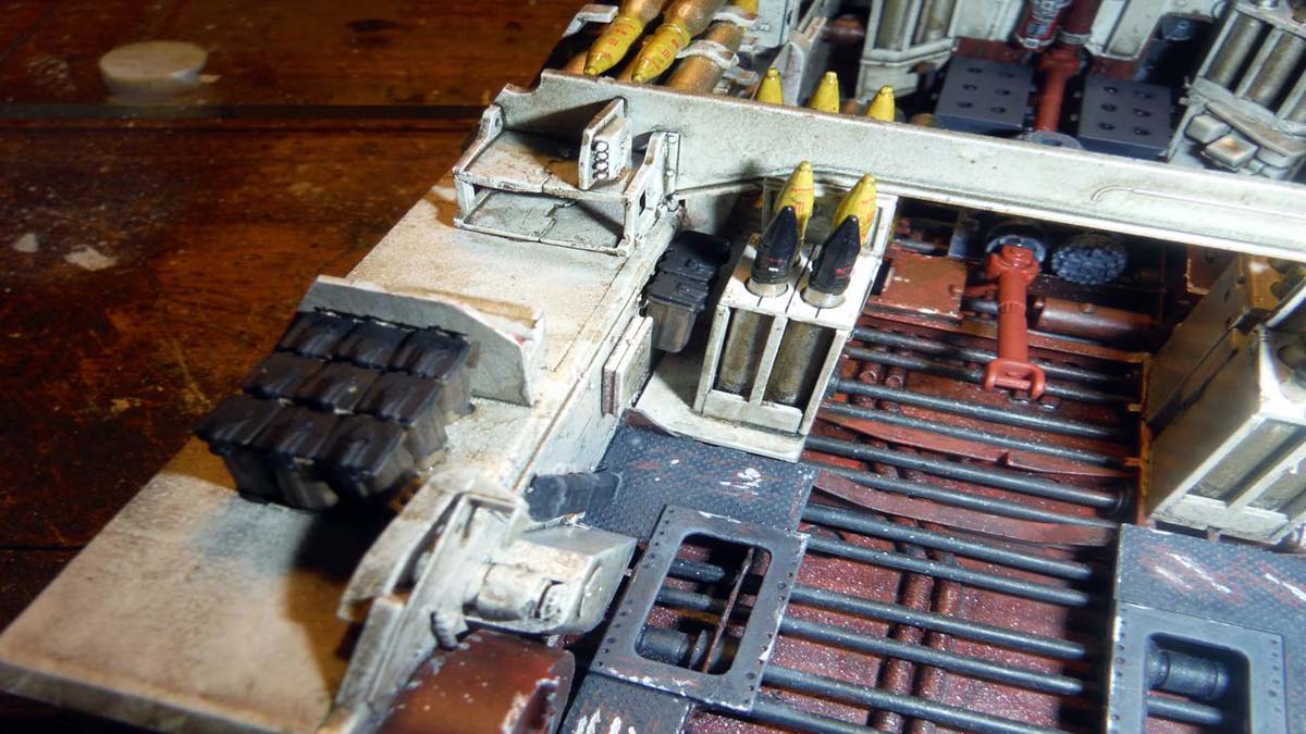
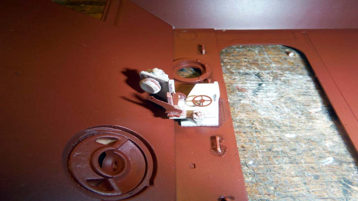
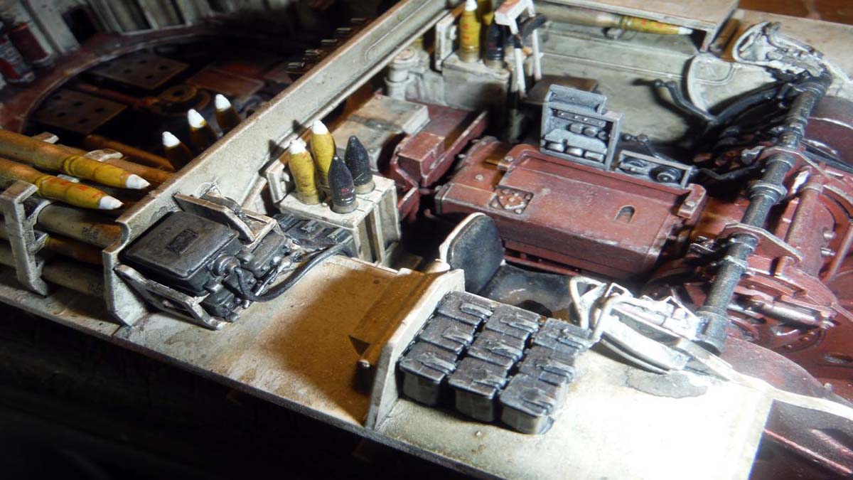
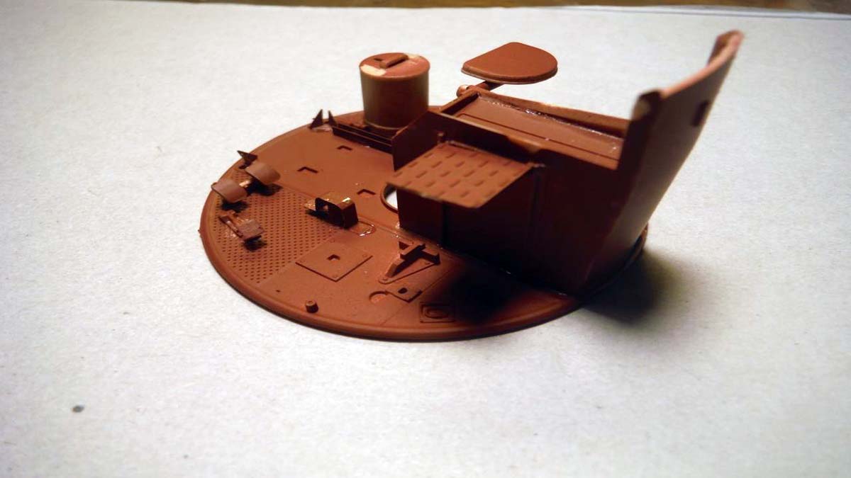
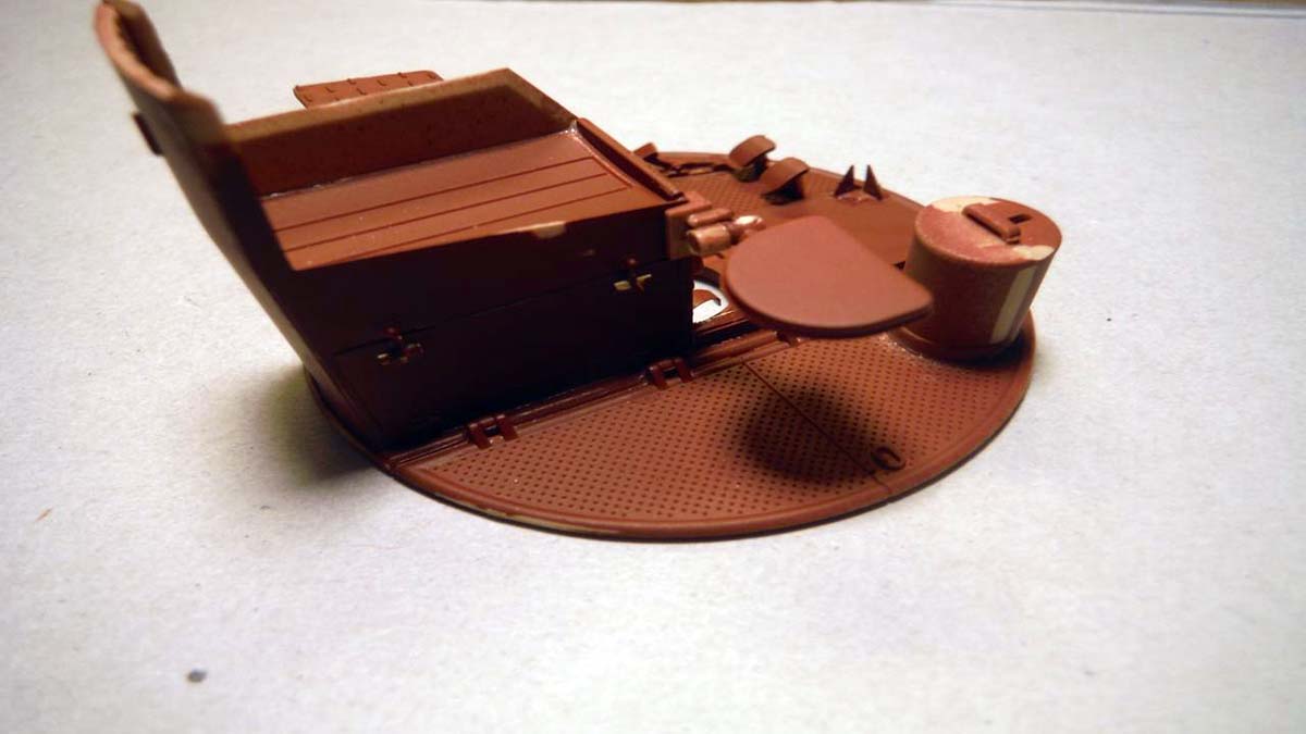
Back to step 33 and 34. Most of these two steps were added. I left off the seat, battery box, and rounds till later. Right now, everything thing is still oxide red other than the torsion bars. At this point, you can mask off the interior to paint the Cremeweis color. Again, in step 35, the seat was left off for ease of painting.
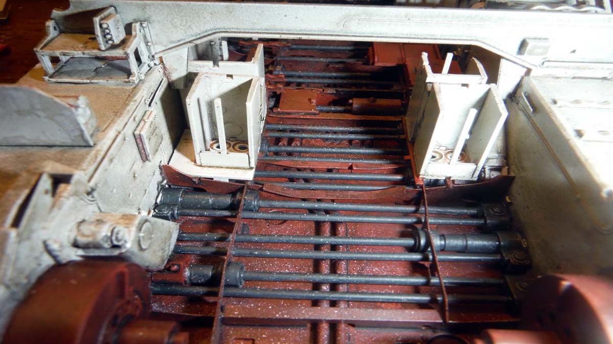
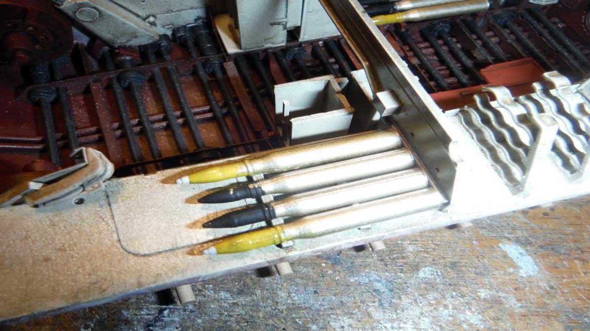
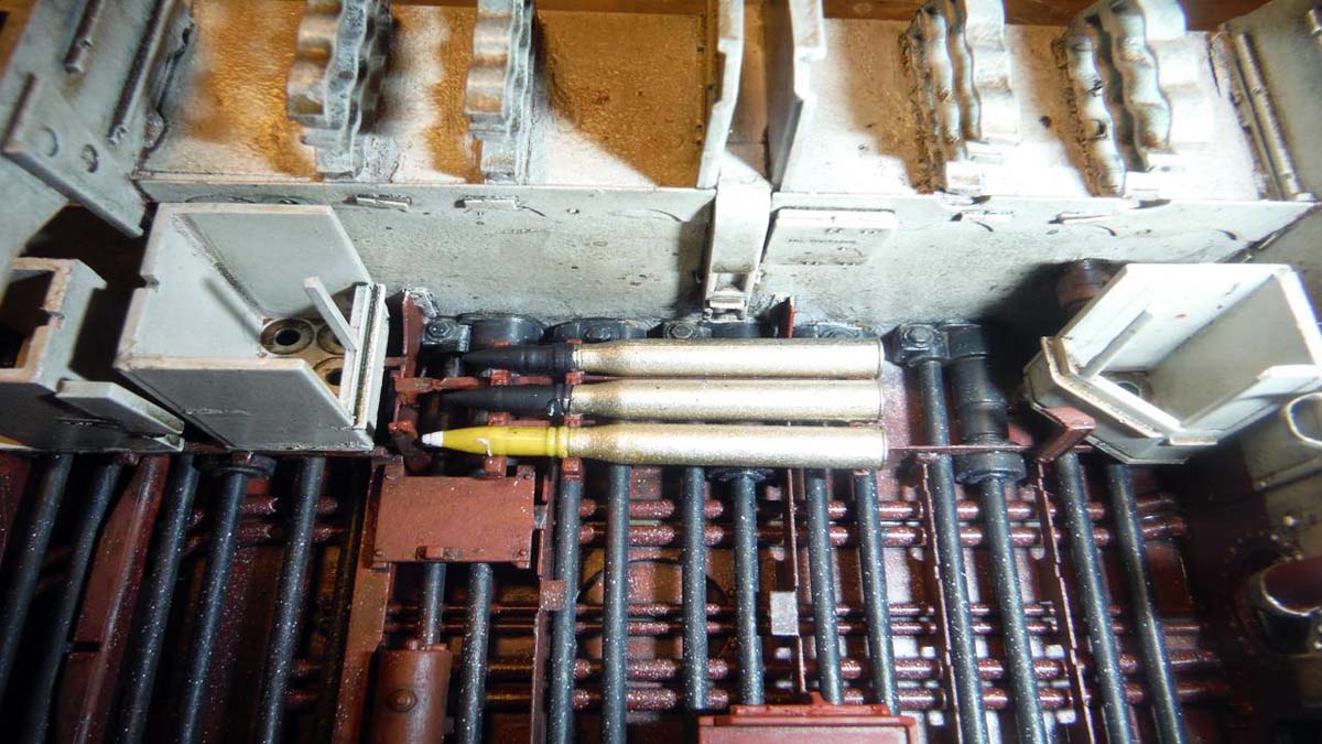
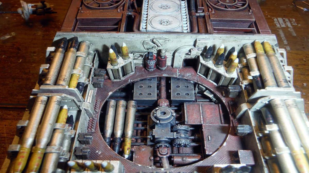
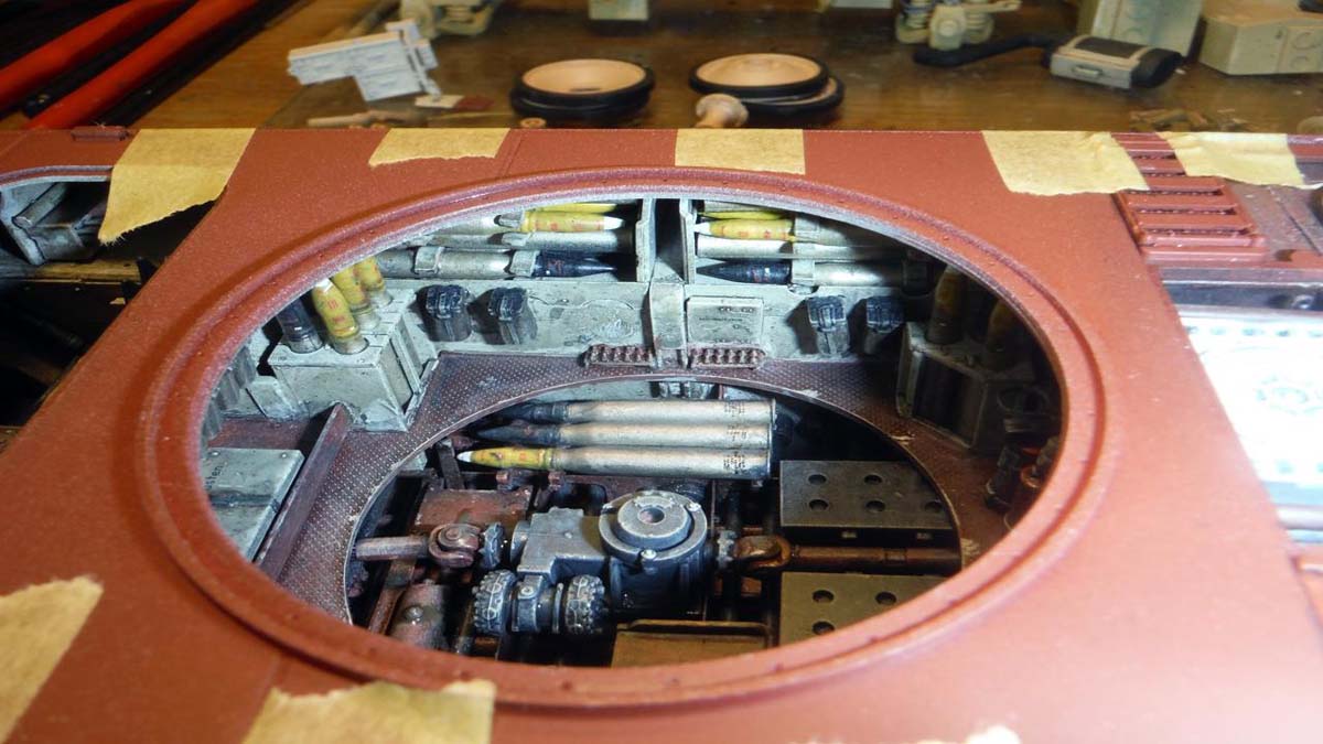
I skipped Step 35, sub step C11 and C12, step 36, and the beginning of step 36. These are the ammo bins. At this point, I hadnt painted the ammo yet which is one of the reasons why I skipped these steps. Second reason was that I thought it would be easier to place all the smaller parts and then drop in the bins.
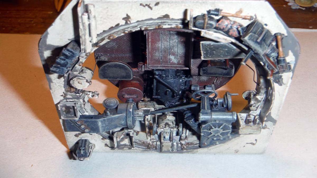
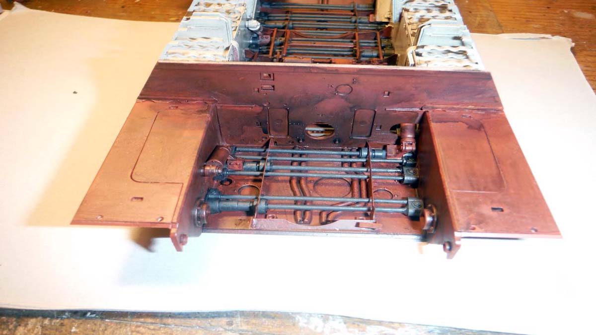
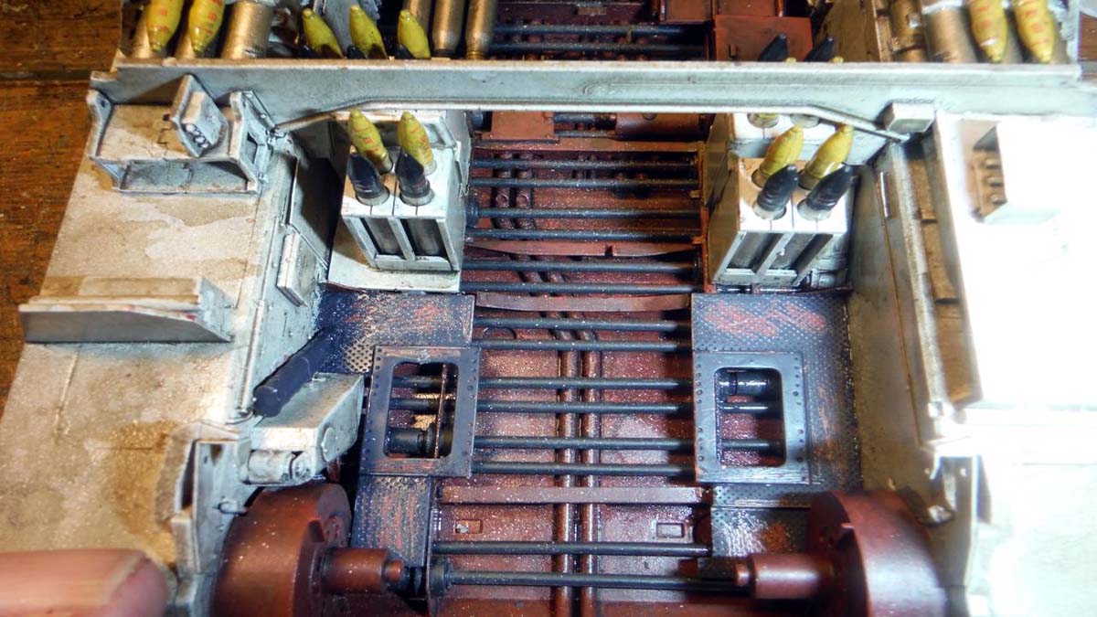
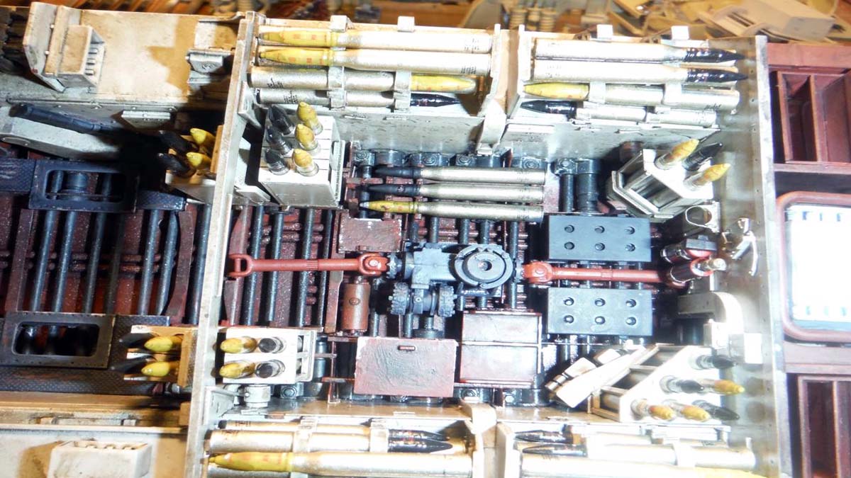
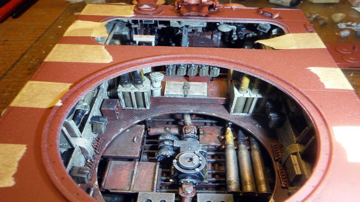
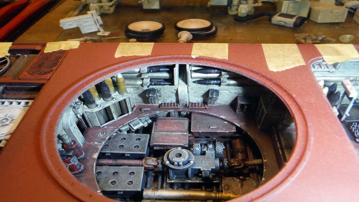
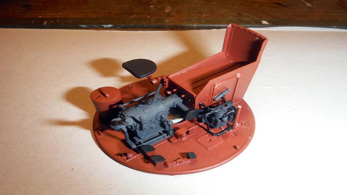
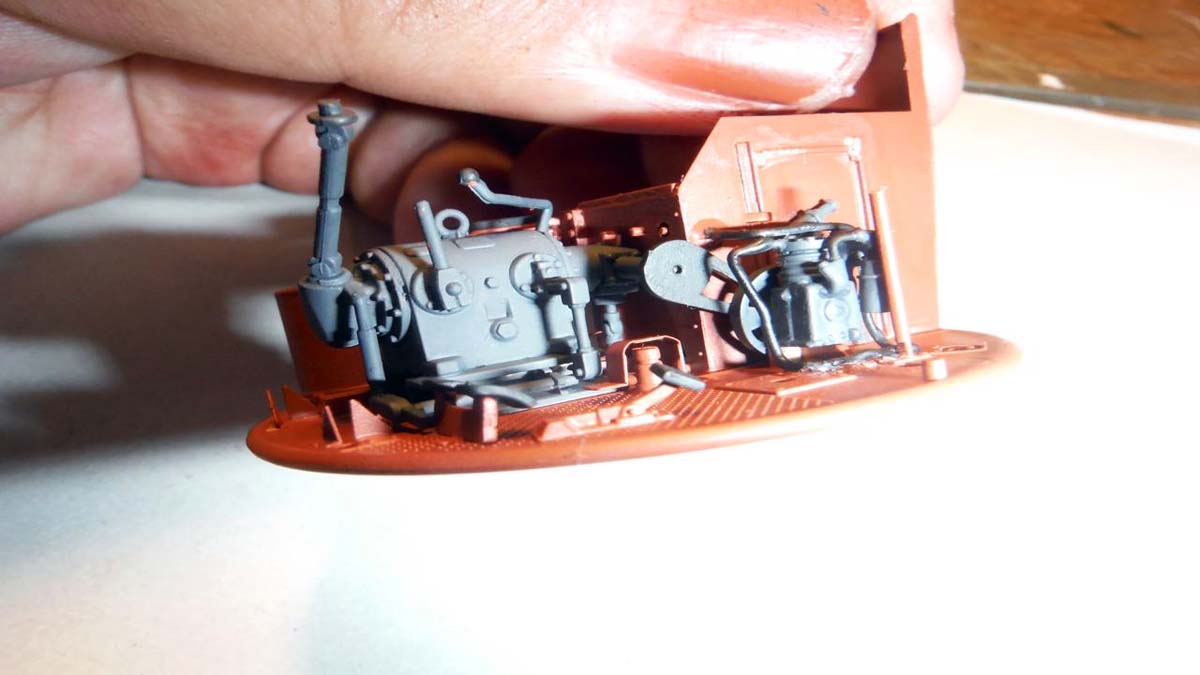
Step 42 drops the transmission in, but attach part K6 after you do step 43, hoses to transmission. Also, in this step, your dropping in the turret drive and drive shaft. Part D27 is not shown in the build box of the turret drive, but is shown in the completed picture that the box is pointing to.
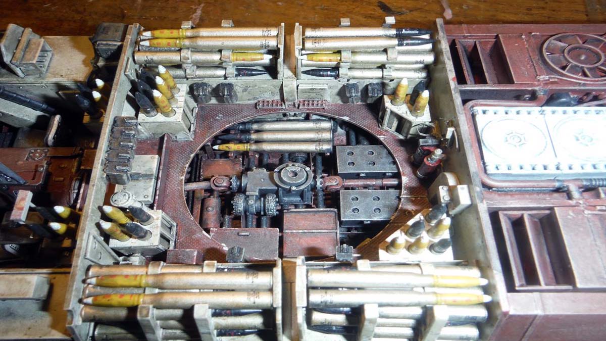
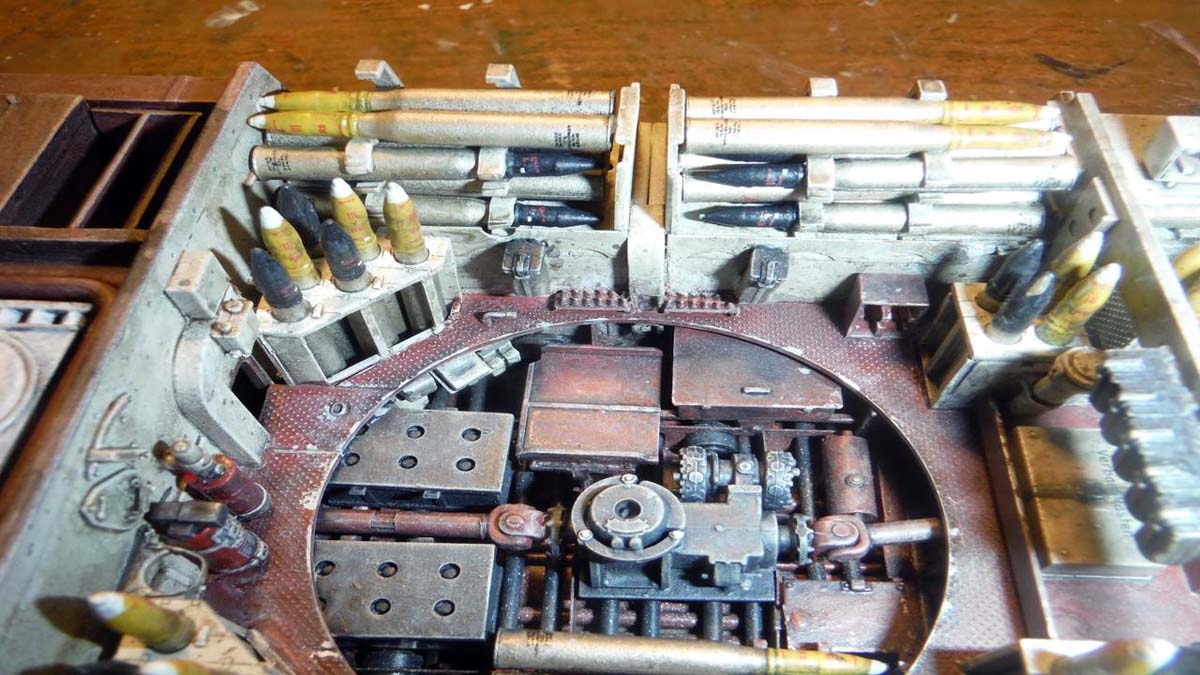
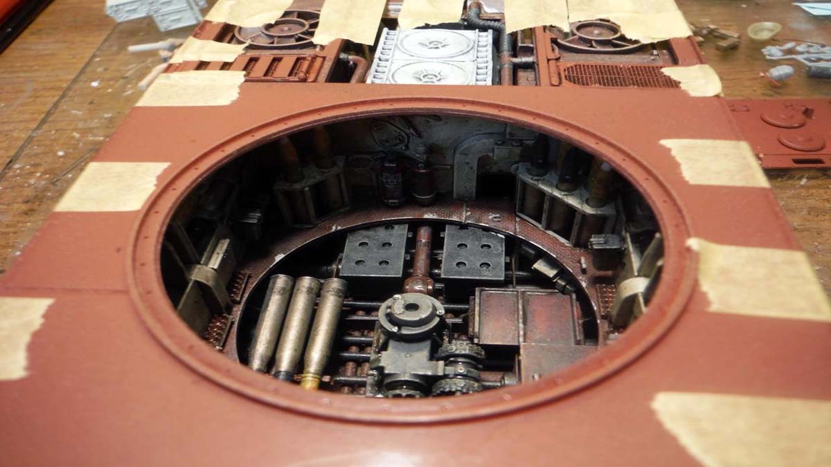
Before going on to step 44, finish completing the ammo boxes and ammo. Attach all the ammo bins and then drop in the hull turret floor. Complete step 45 and 46 as seen.
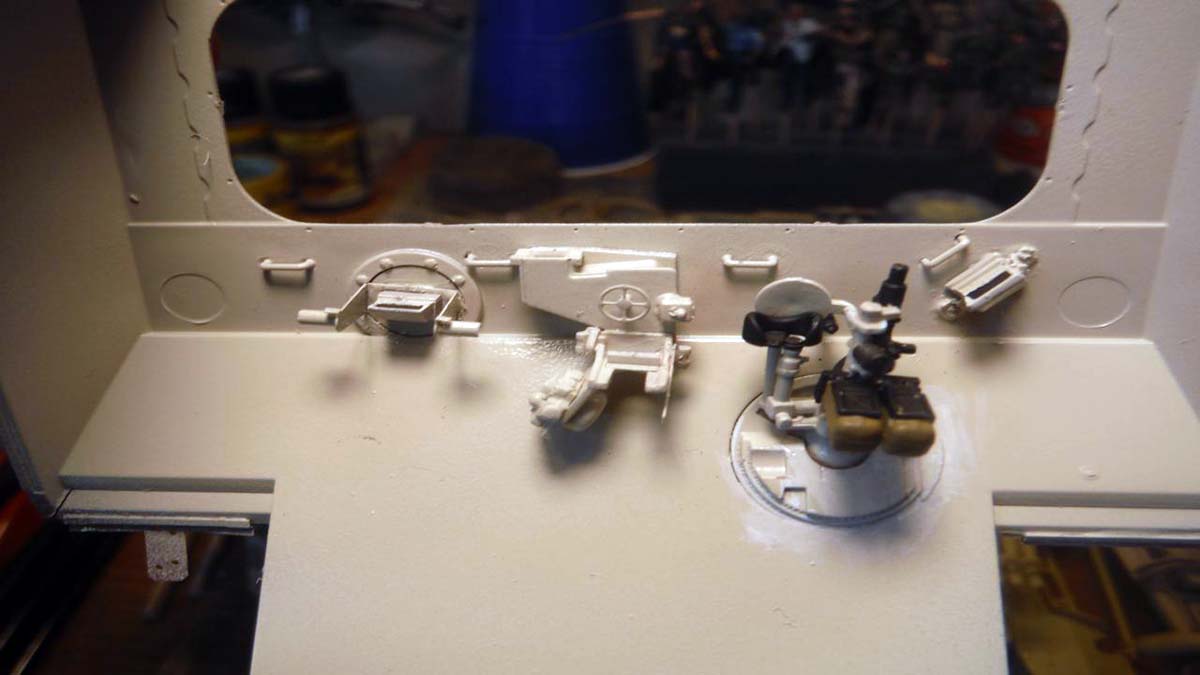
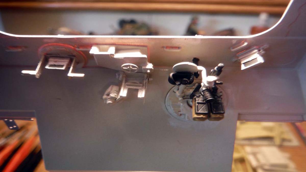
In step 47, I left the radio components out of the rack (K47) until I painted them and wired them up. The rest of step 47 and all of step 48 went without problems.
Step 49 went without any problems. The only correction was that the decals for the fire extinguisher were not called out. On part H29, you need to add decals 7 and 28.
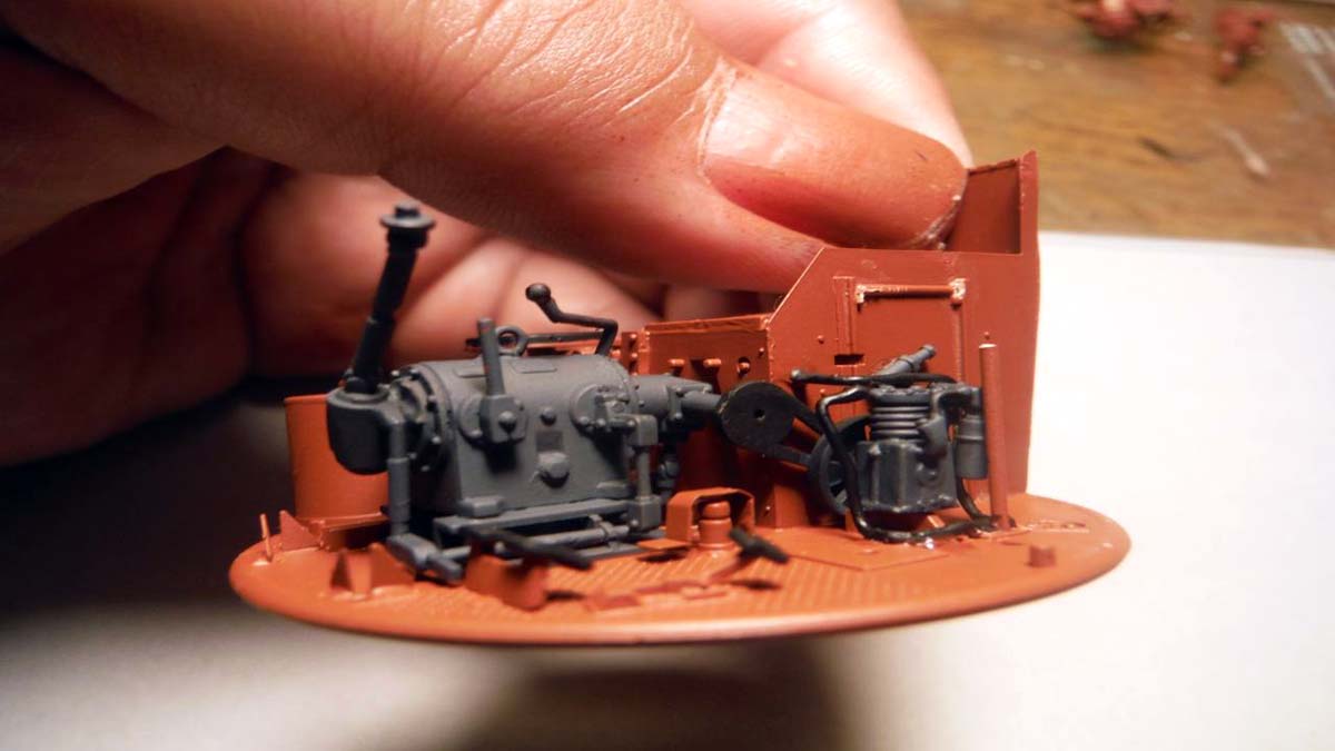
The only thing I would suggest in steps 50, 51, and 52 is wait and glue part D58 (drive shaft) when you install the completed engine. In step 60 and 61, you drop in the engine and attach 3 hoses. Be patient and make sure hoses (K35/36, K37/38, K83/84) align up properly with engine and side fire walls.
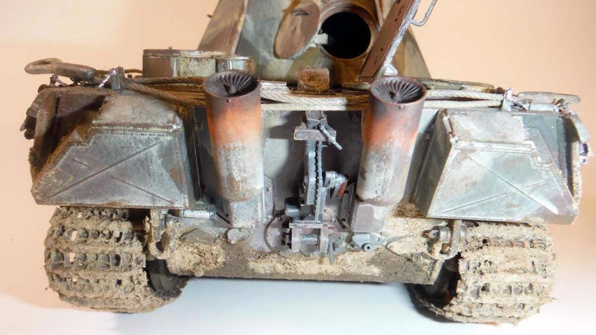
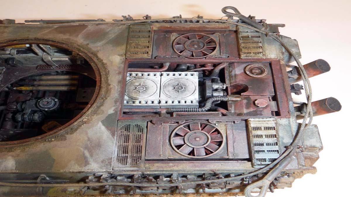
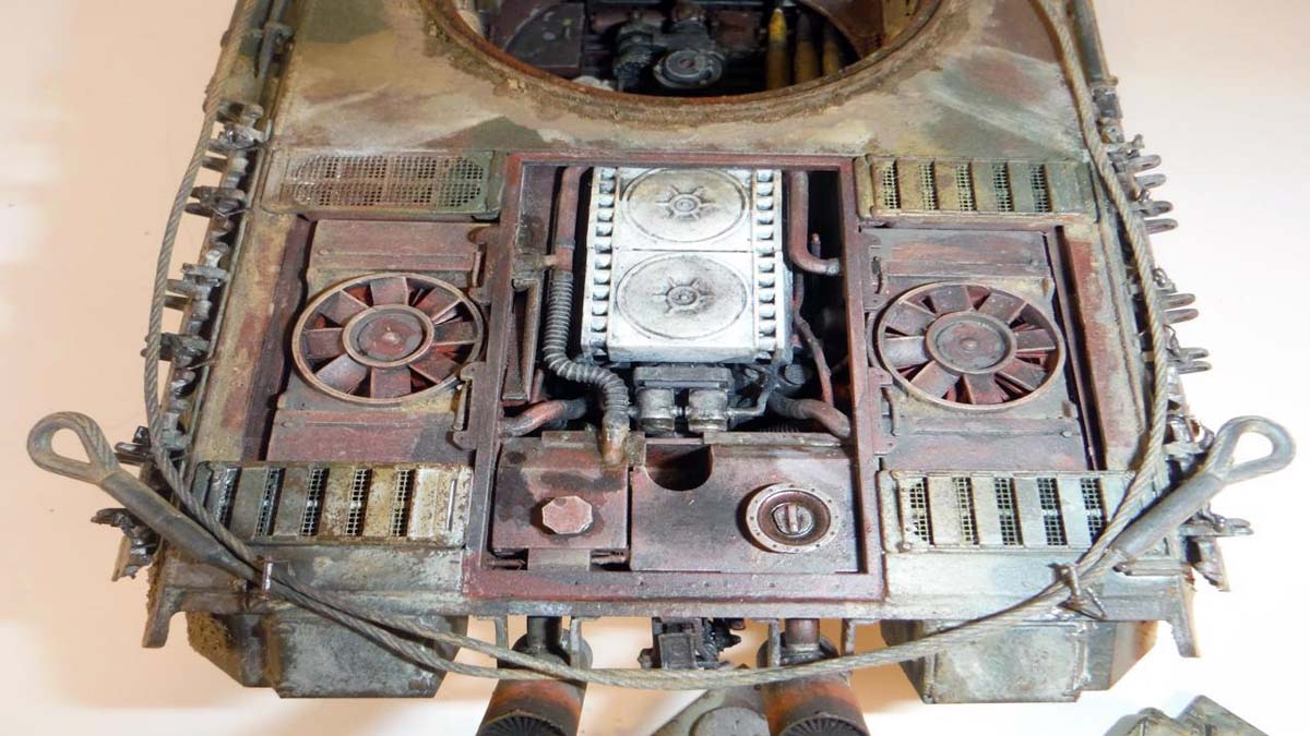
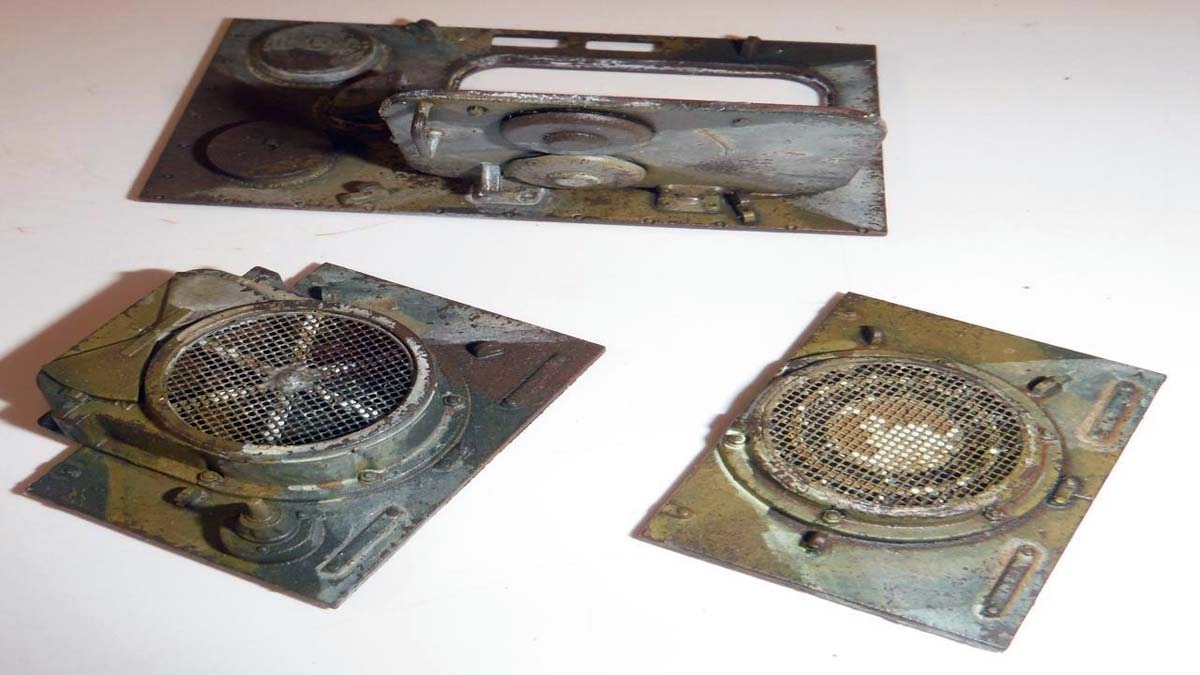
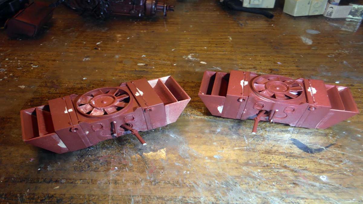
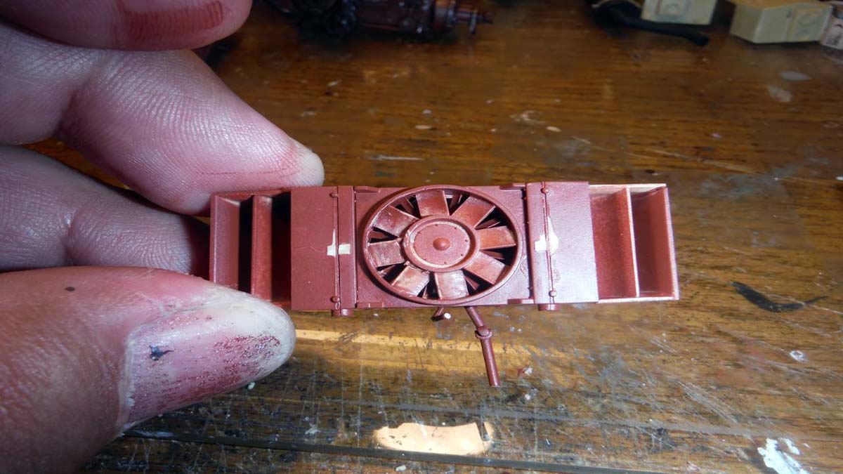
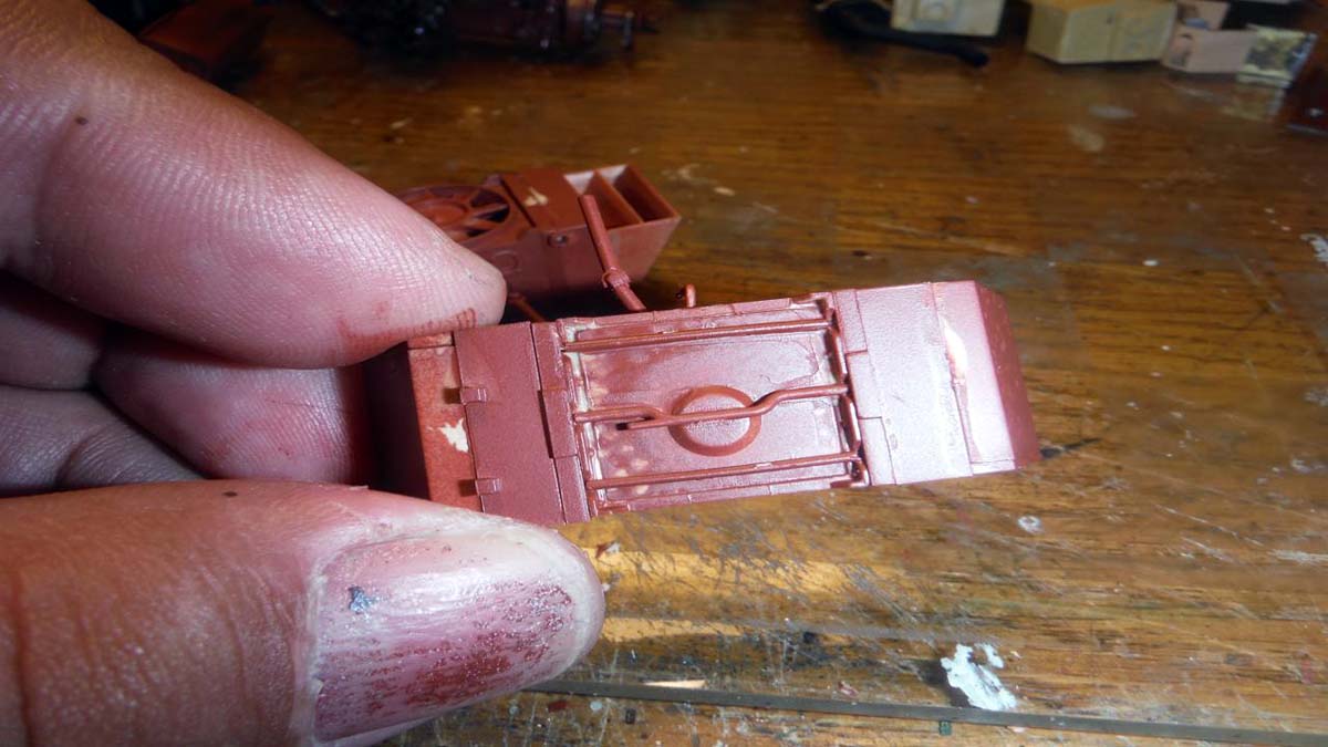
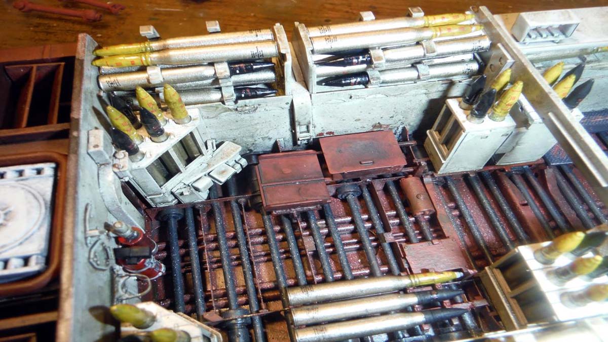
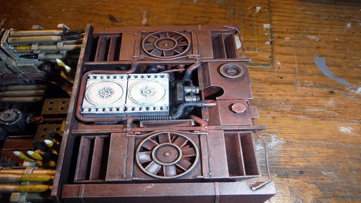
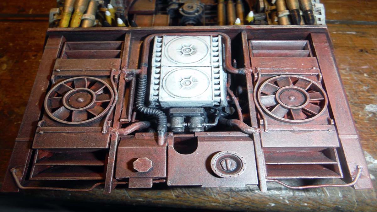
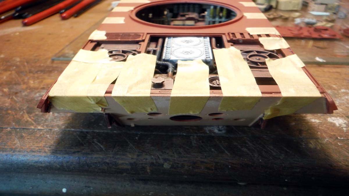
Step 61, sub steps C18, C19, and C20 are the radiators. No issue with building these, but installing is where it becomes weird as far as the instructions go. There is no step for installing the radiators but rather it is just on page 40. Page 40 also included building the fuel tanks, radiator and fuel filler, and last of the hoses. At this point, you can attach the rear fire wall, part F2. Make sure you drill out the appropriate holes in the fire wall according to what vehicle your building before you attach it. On page 41 are sub steps C21 through C30 continuing on to page 42, sub steps C31 and C32. These are all the components that attach to rear of the vehicle in step 64 and 65.
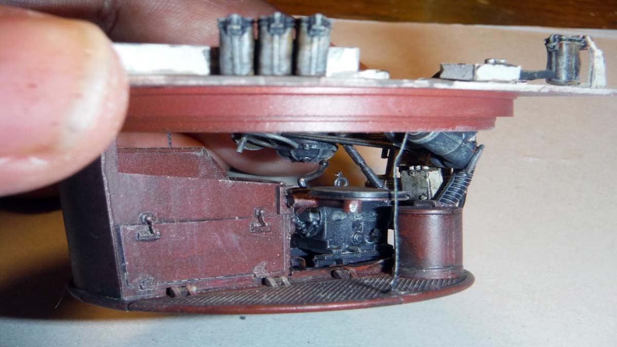
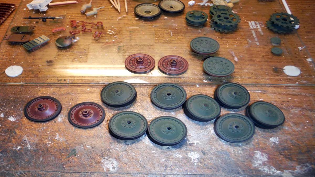
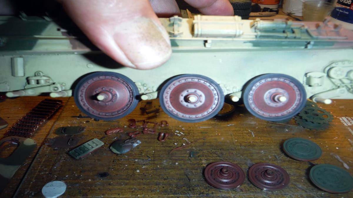
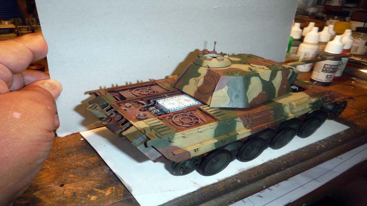
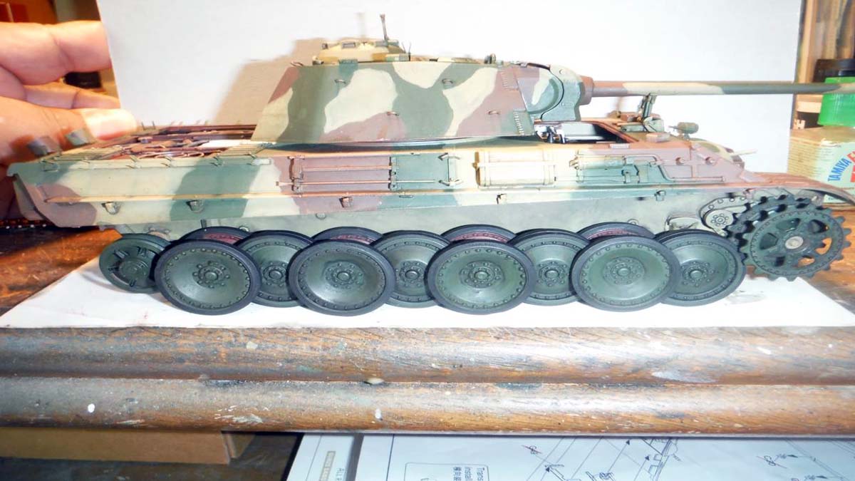
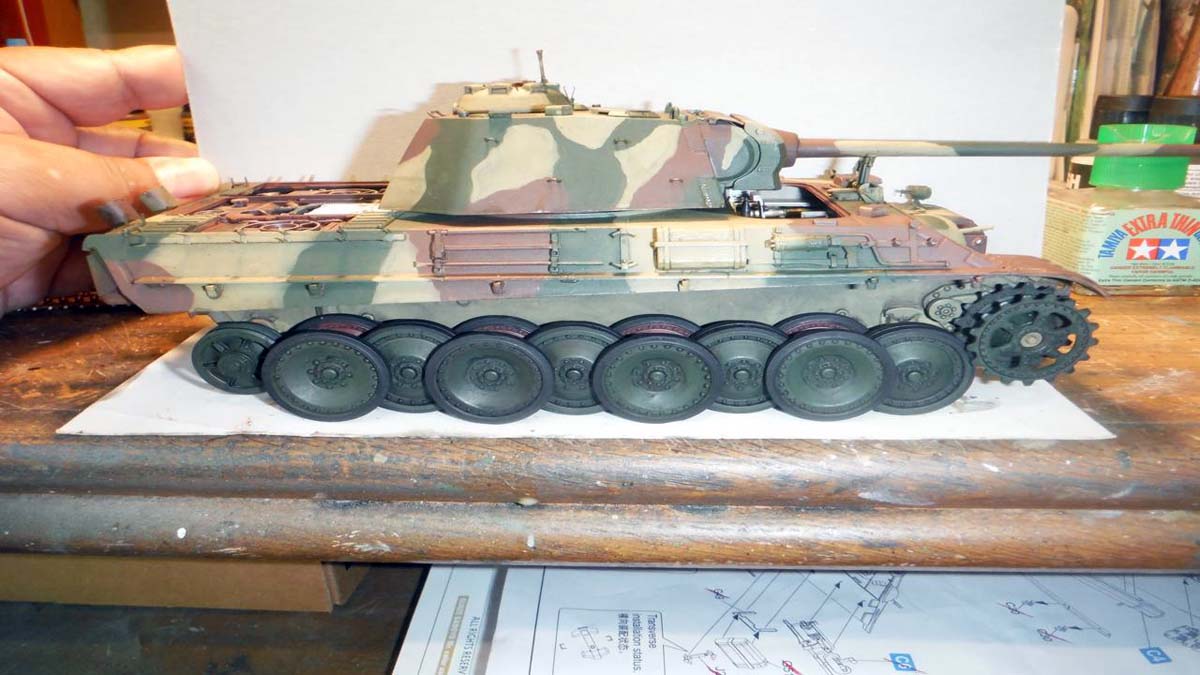
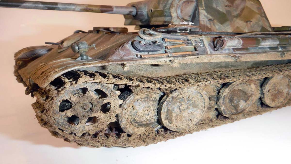
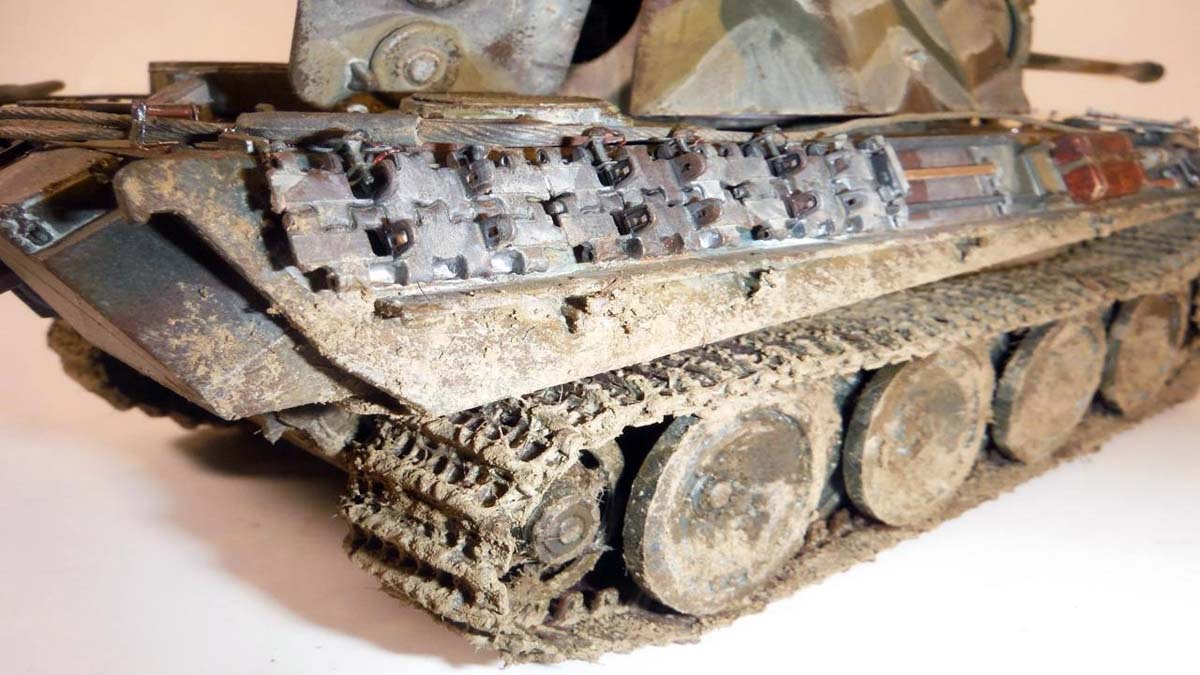
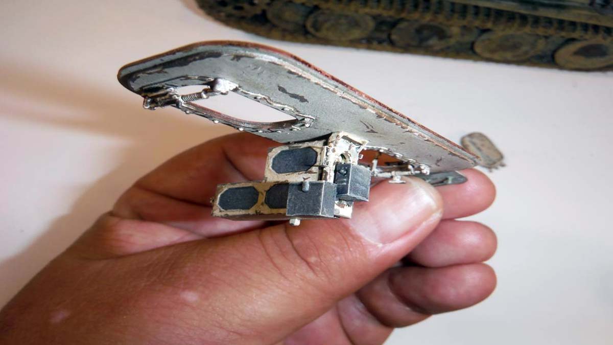
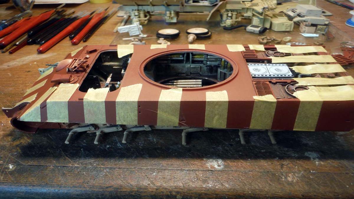
Steps 66, 67, 68, and 69 are road wheel building. All was straight forward, but I did find a big problem when it came to attaching the road wheels and the tracks. If you choose the January 1945 Ausf. G color scheme as I did, the last wheel, according to the drawing is one of the steel road wheels provided. Thats not the problem. The problem is that if you chose not to have the road arms working and you glued them, that is going to create a gap between the track and that last rear steel road wheel. Reason is that there is no rubber around the wheel like the rest creating a little bit of height. So, if you're going to use the steel wheels, dont glue the last road arm and leave it working so that after you attach the tracks, you can tac that road wheel down to the track.
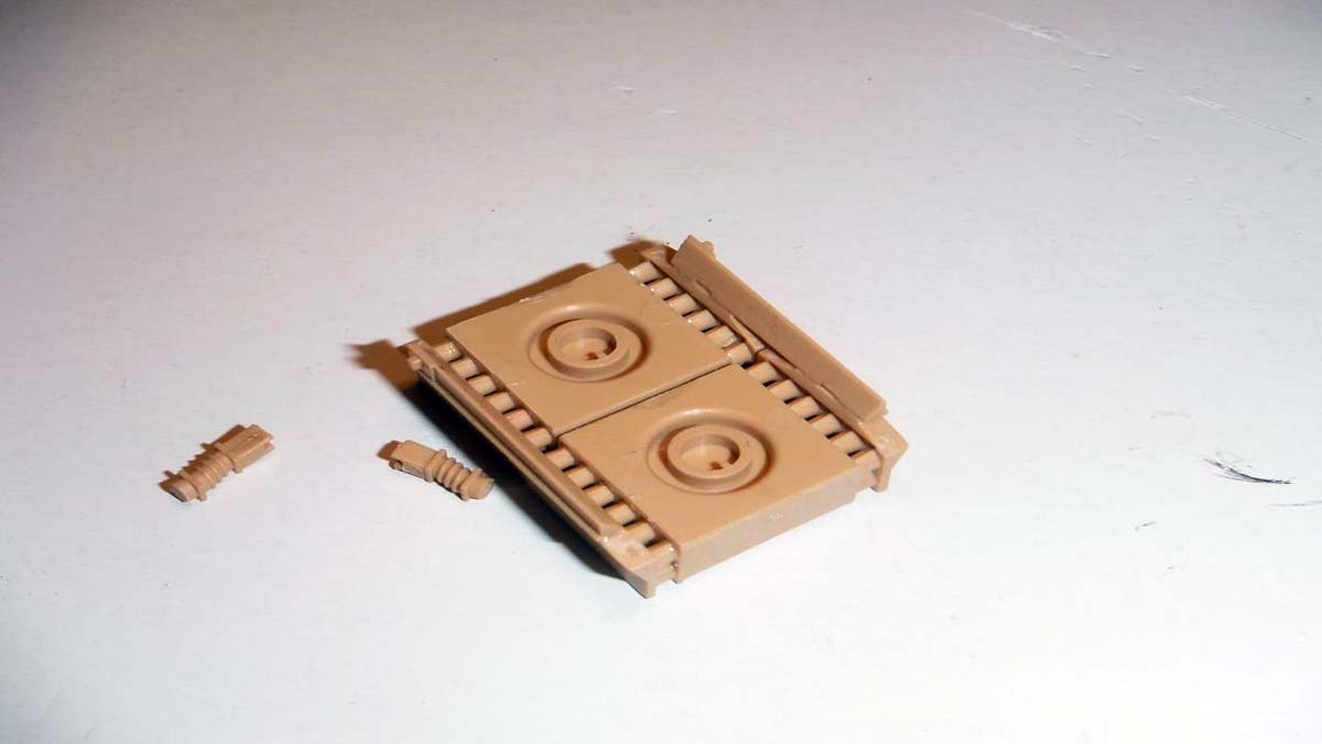
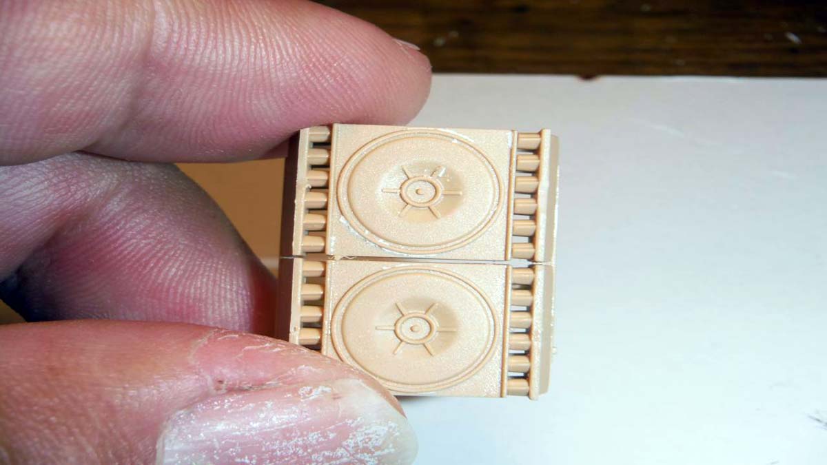
Speaking of tracks, in step 70, track assembly, it looks like the tracks are to be workable, but they are not. I went ahead and painted the tracks first a rusty color, then assembled them around the sprocket and road wheels. Then I just touched them up where the glue took away some of the paint and later after everything was done, I weathered them with powder.
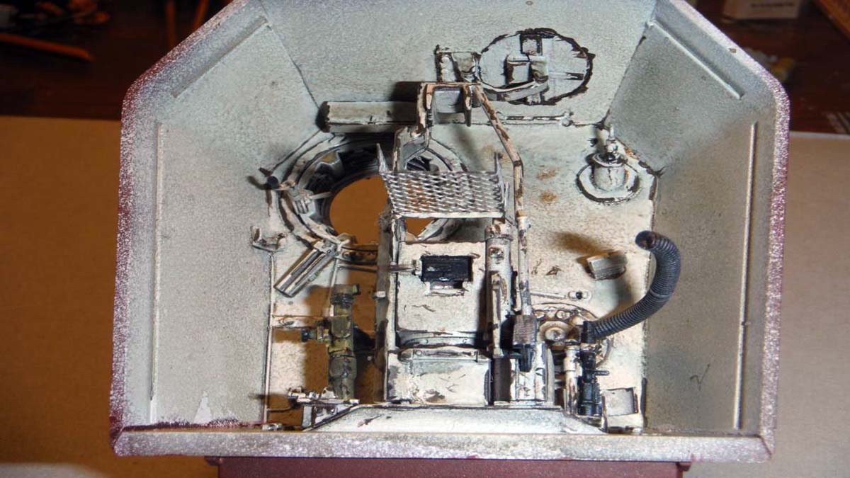
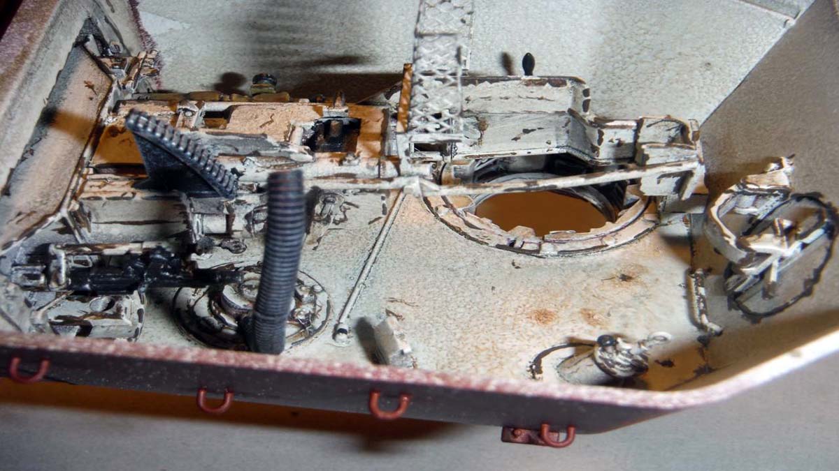
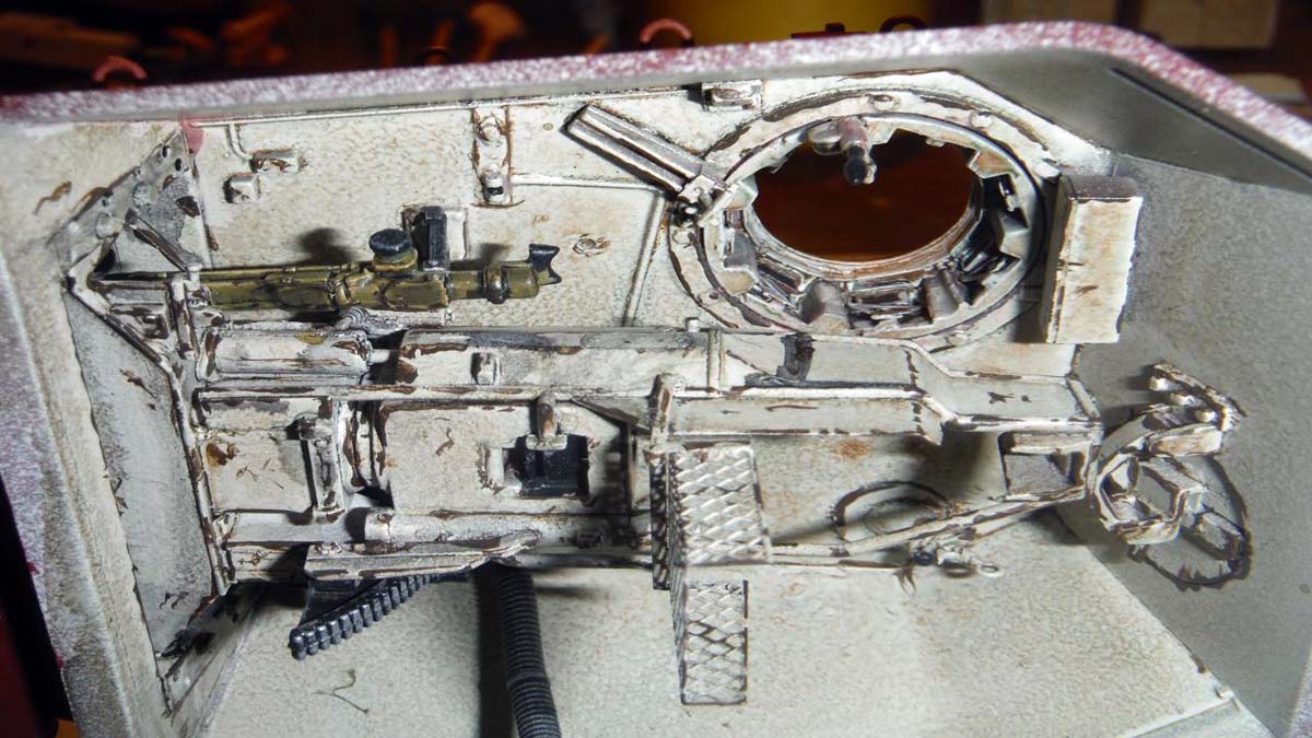
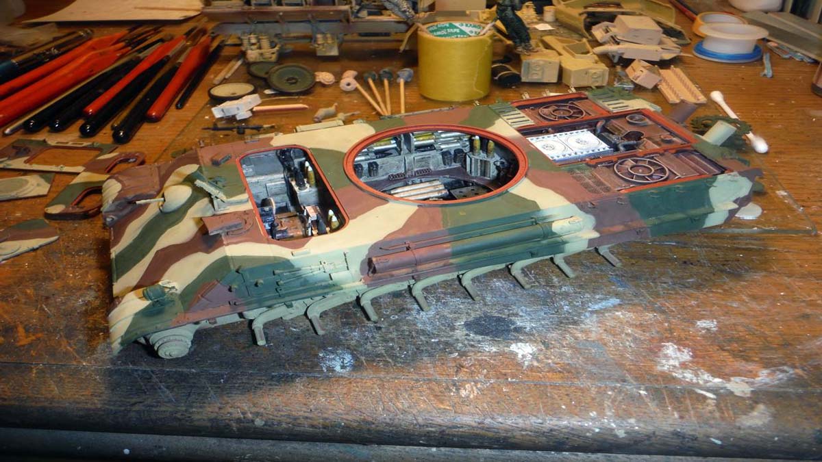
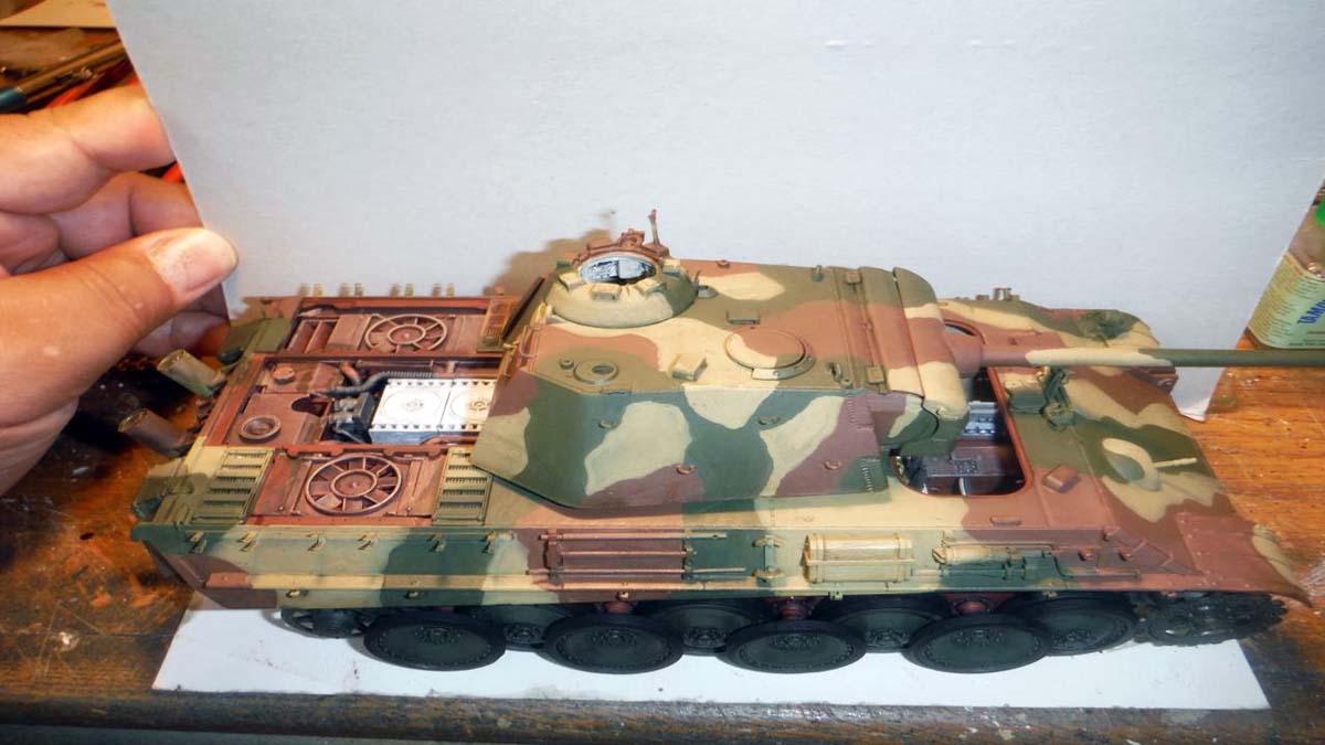
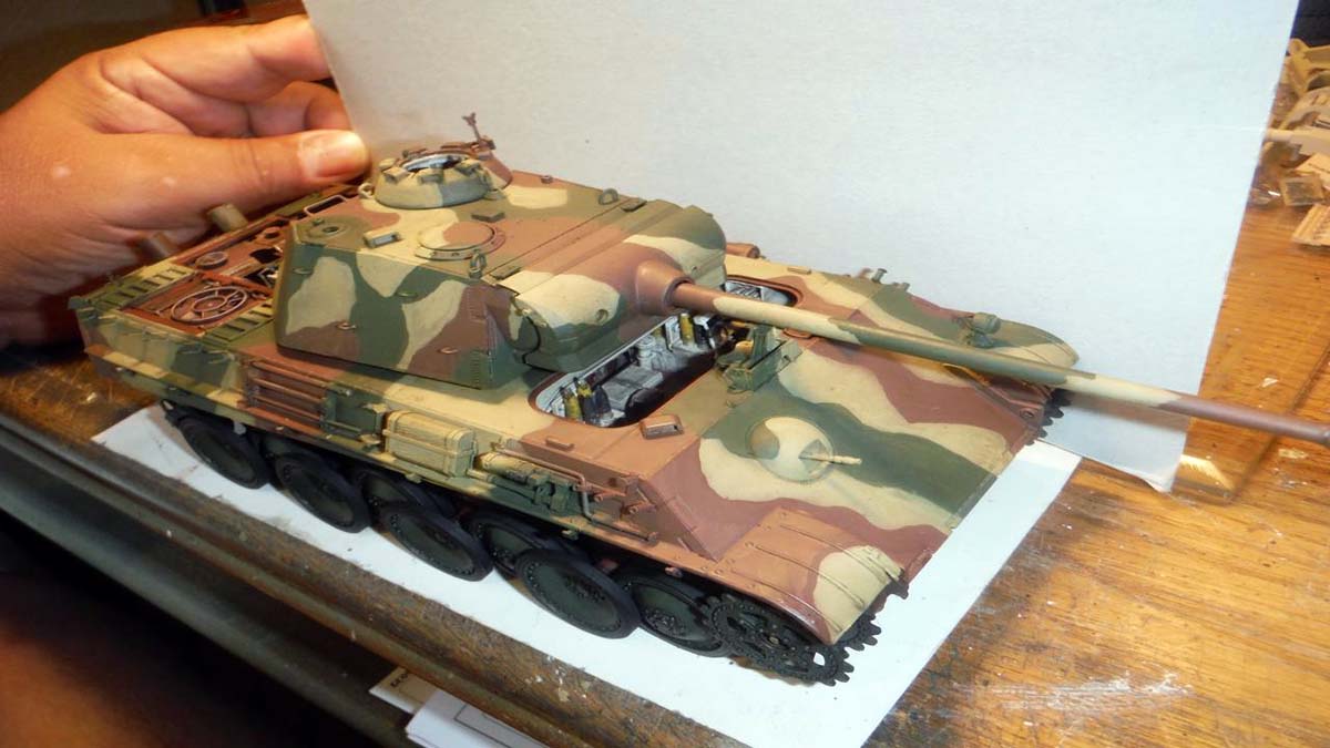
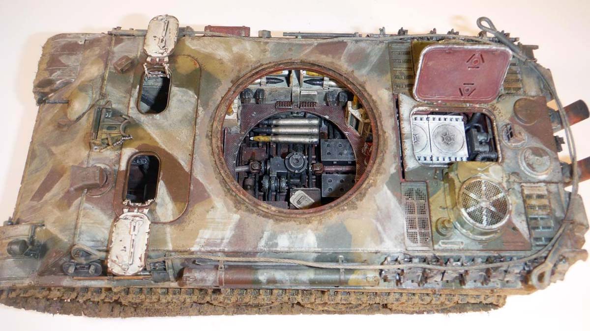
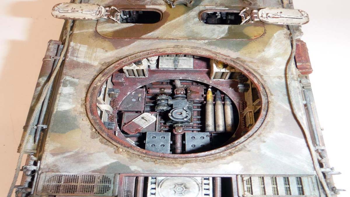
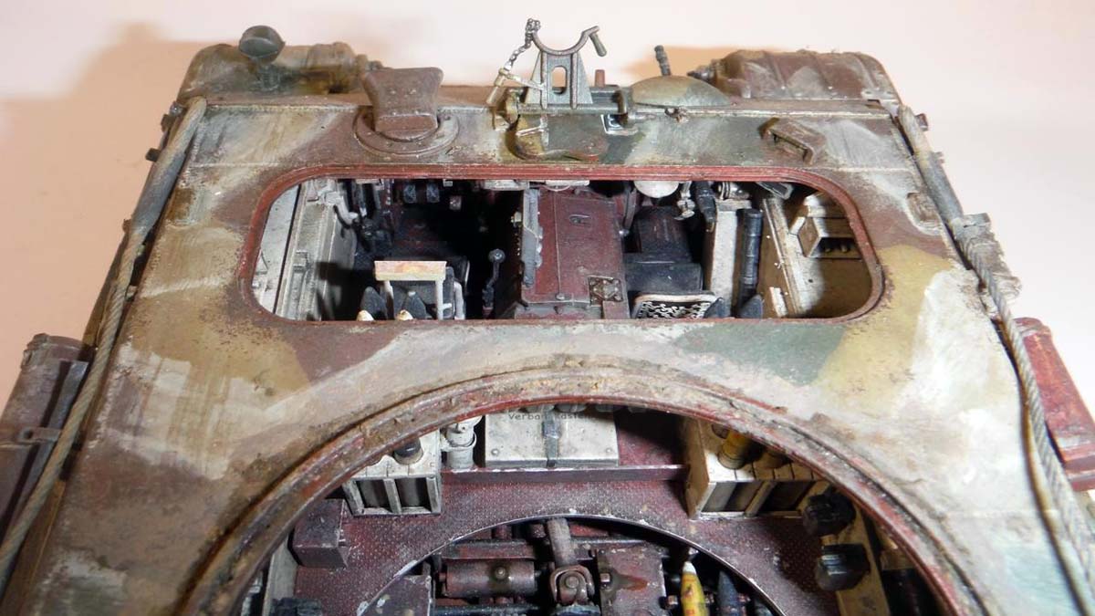
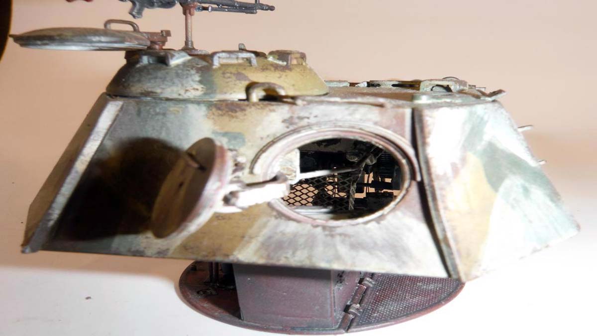
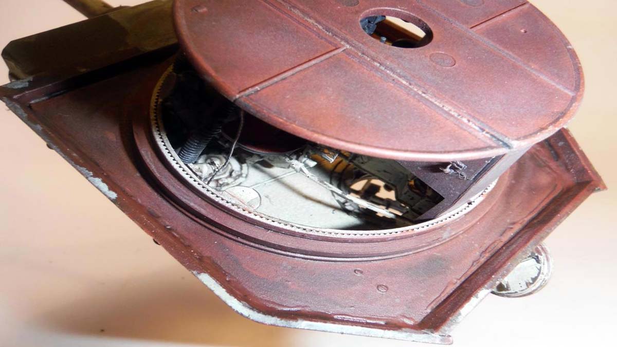
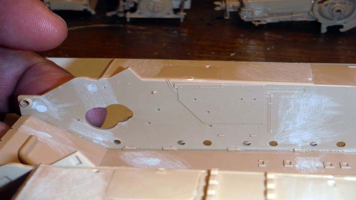
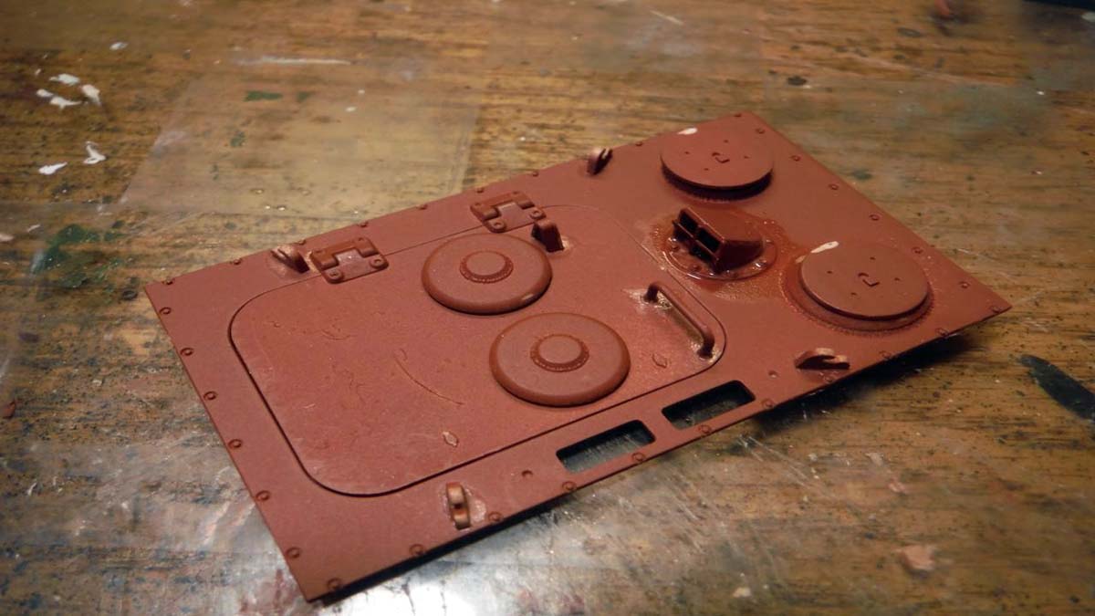
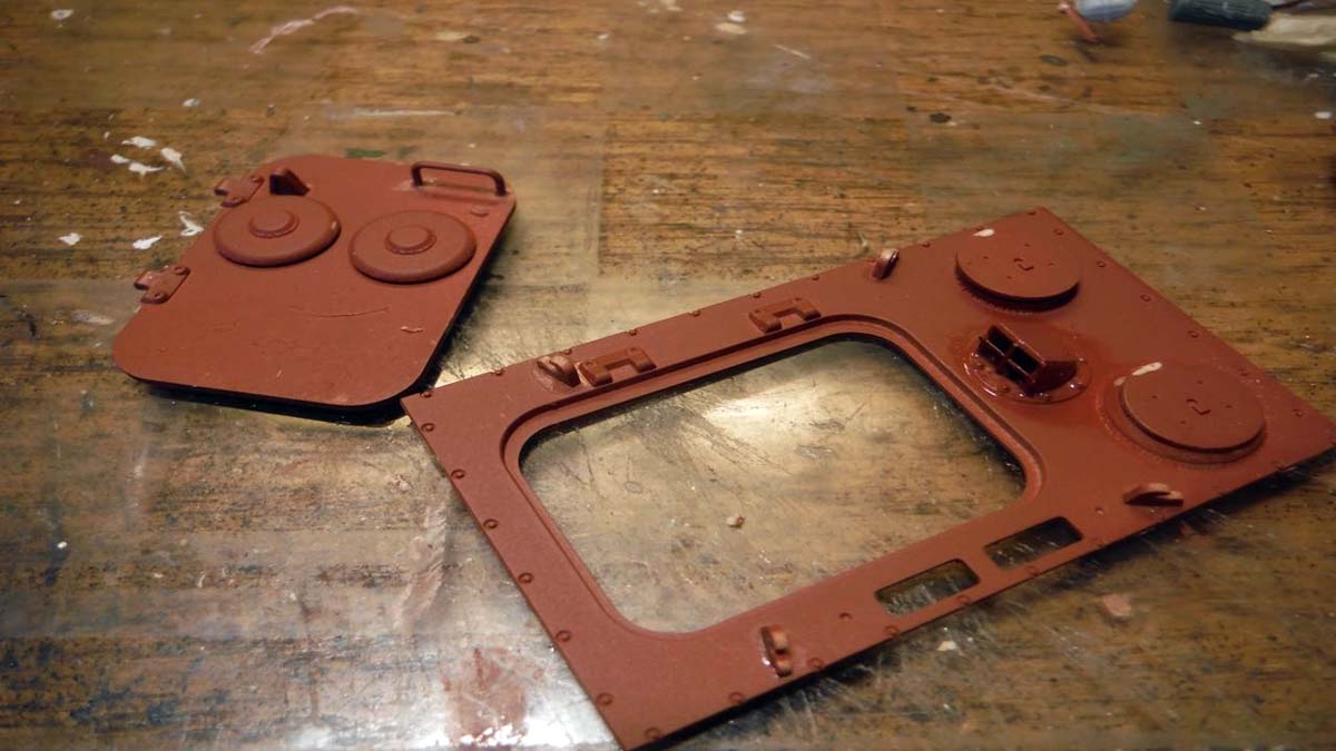
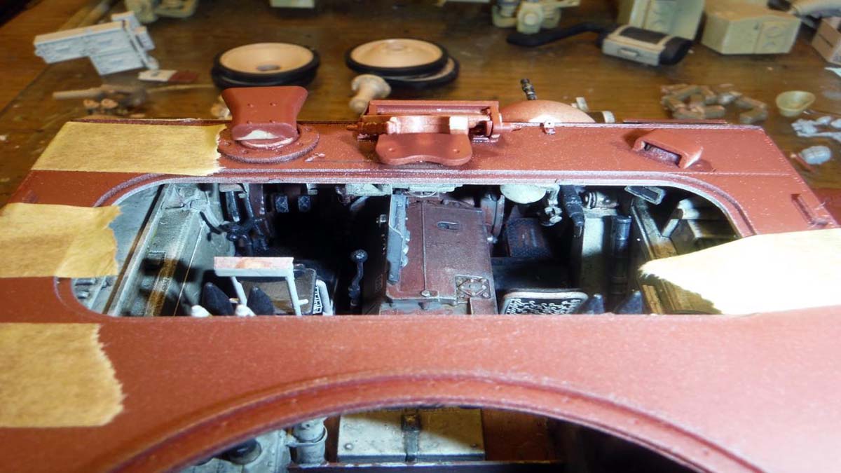
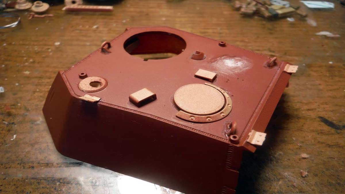
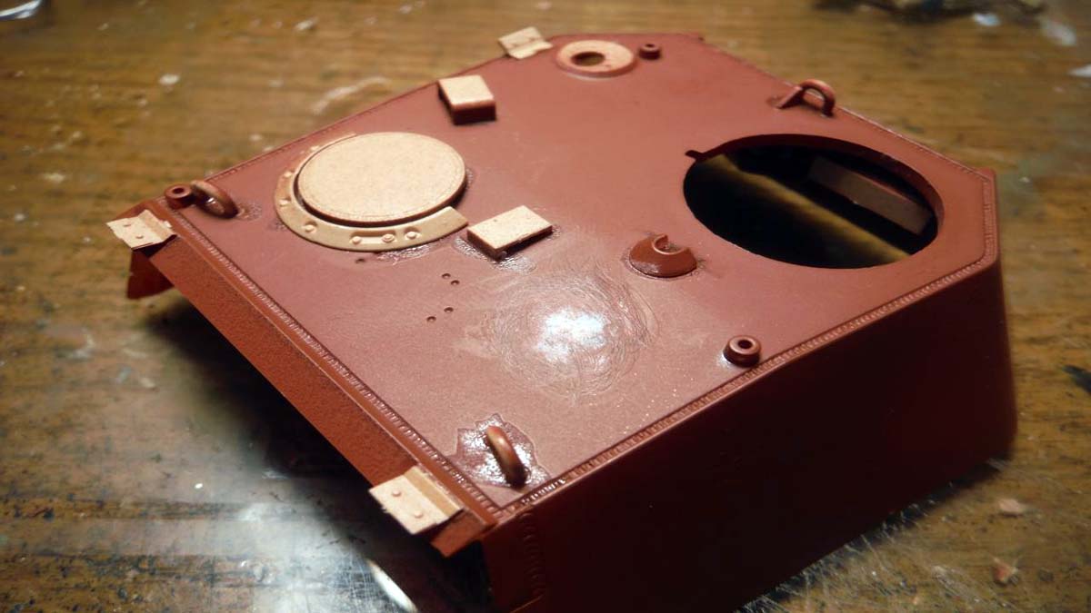
Now back to the upper hull. By now I figured out that I was just going to build this as a regular model and disregard the clear parts. I left the completed hatch component un-glued so that it can be removable to view interior. In step 23, I left off the radios for ease of painting and wiring. Problem here is where some of the radio wires where to go. If you wire the radio, you wouldnt be able to remove the completed hatch assembly. Would have been better if the radio was engineered to be attached to the transmission so wiring can be done. Be careful with all the small parts and work slowly.
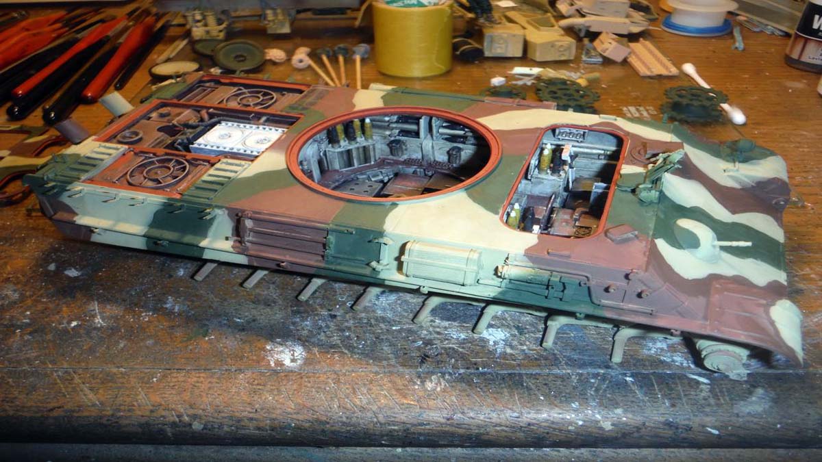
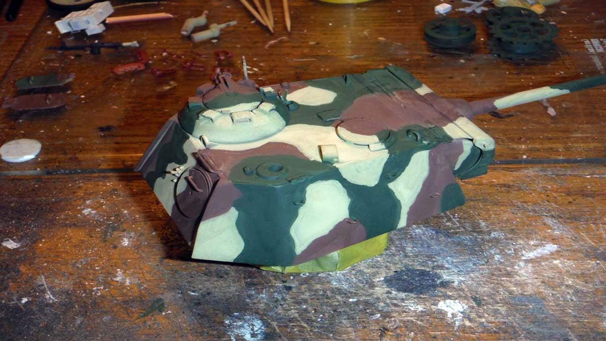
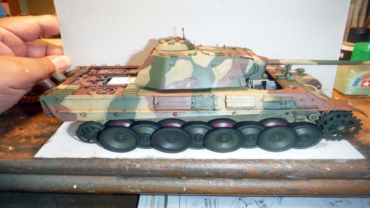
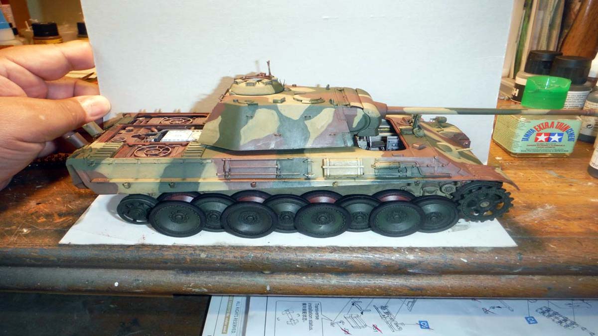
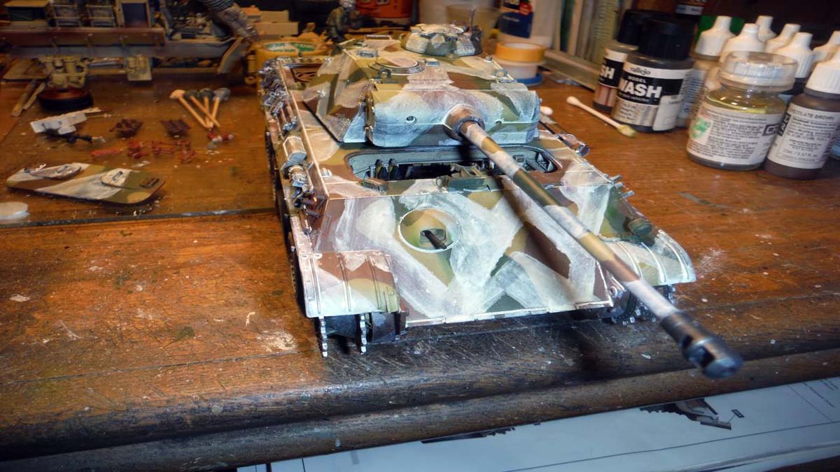
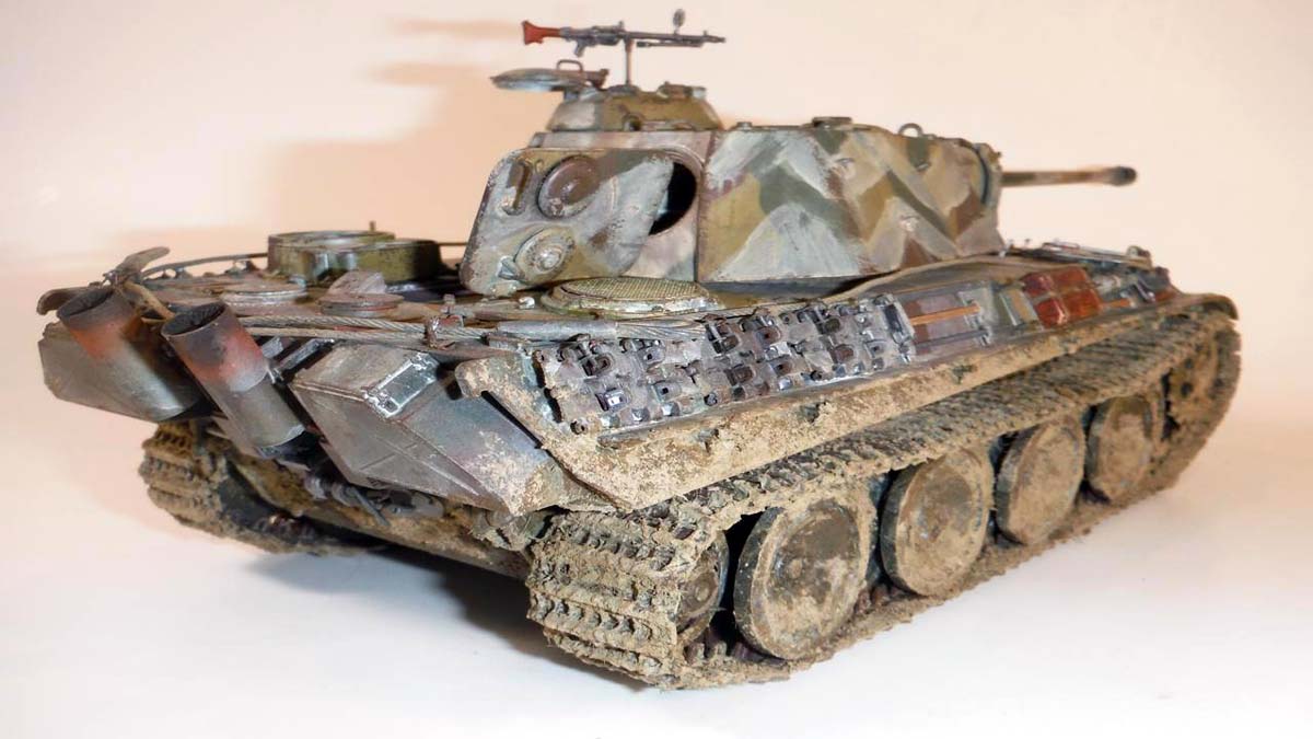
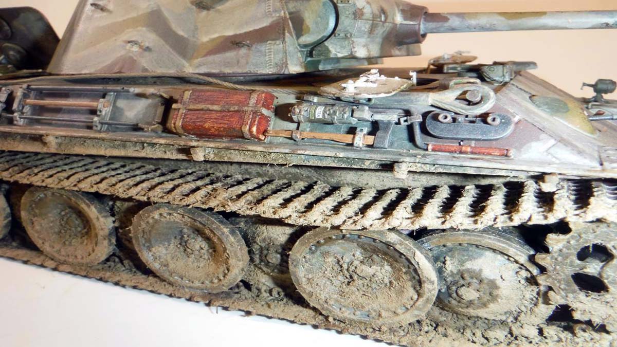
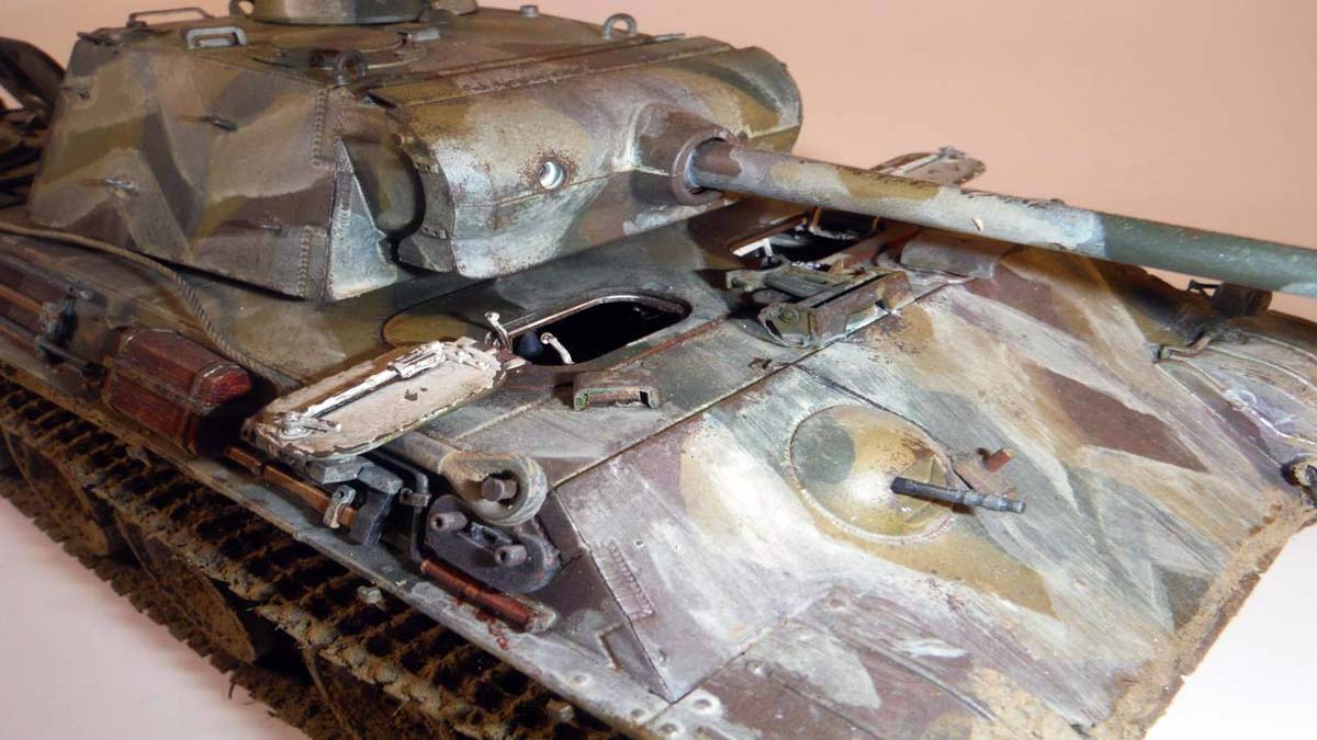
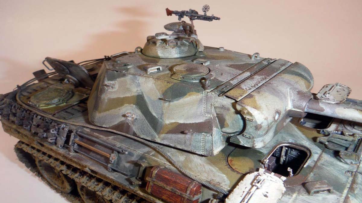
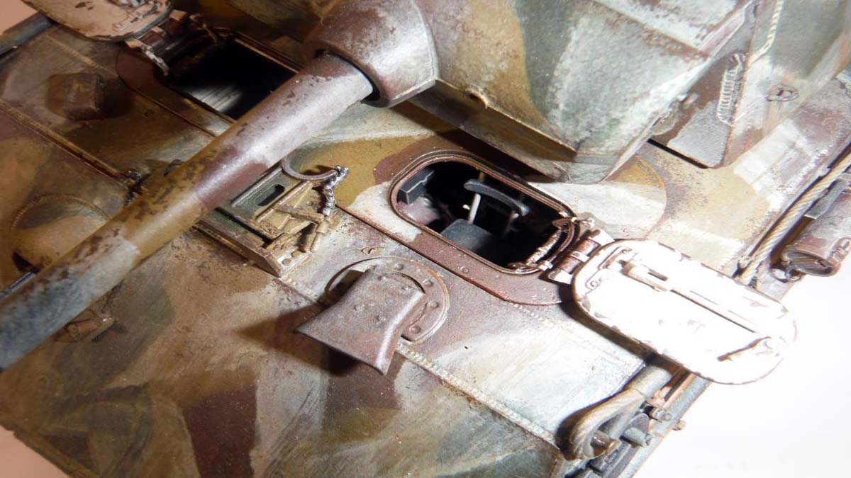
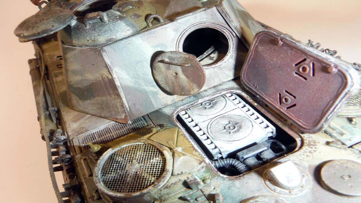
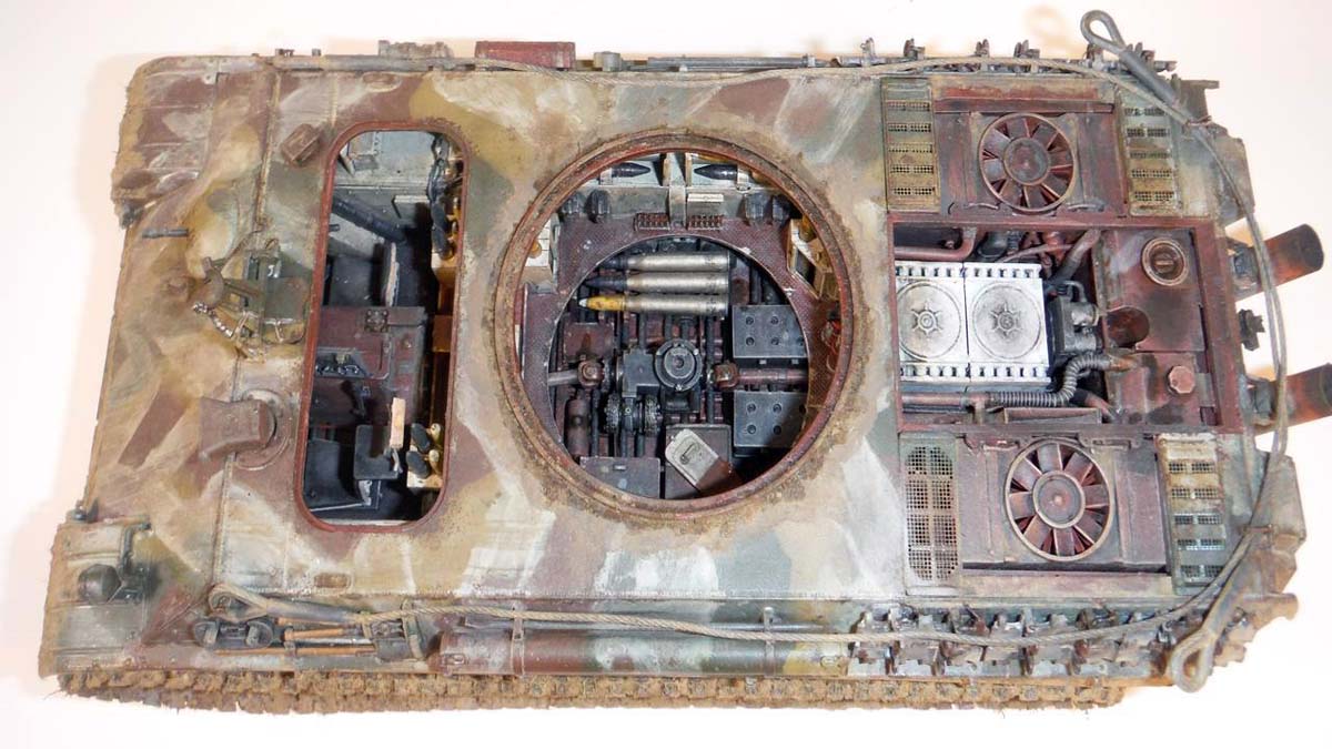
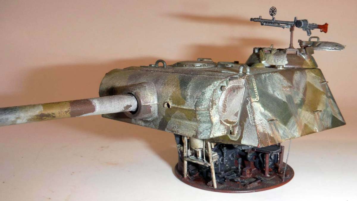
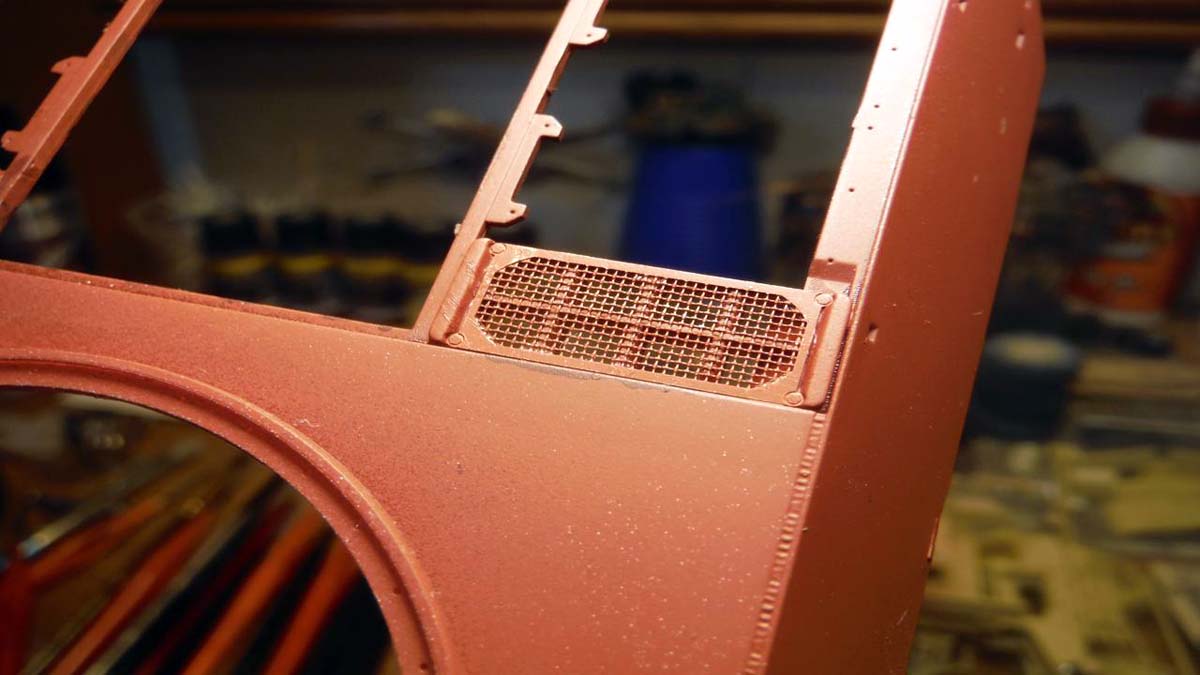
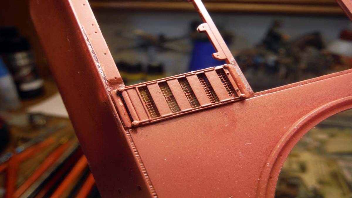
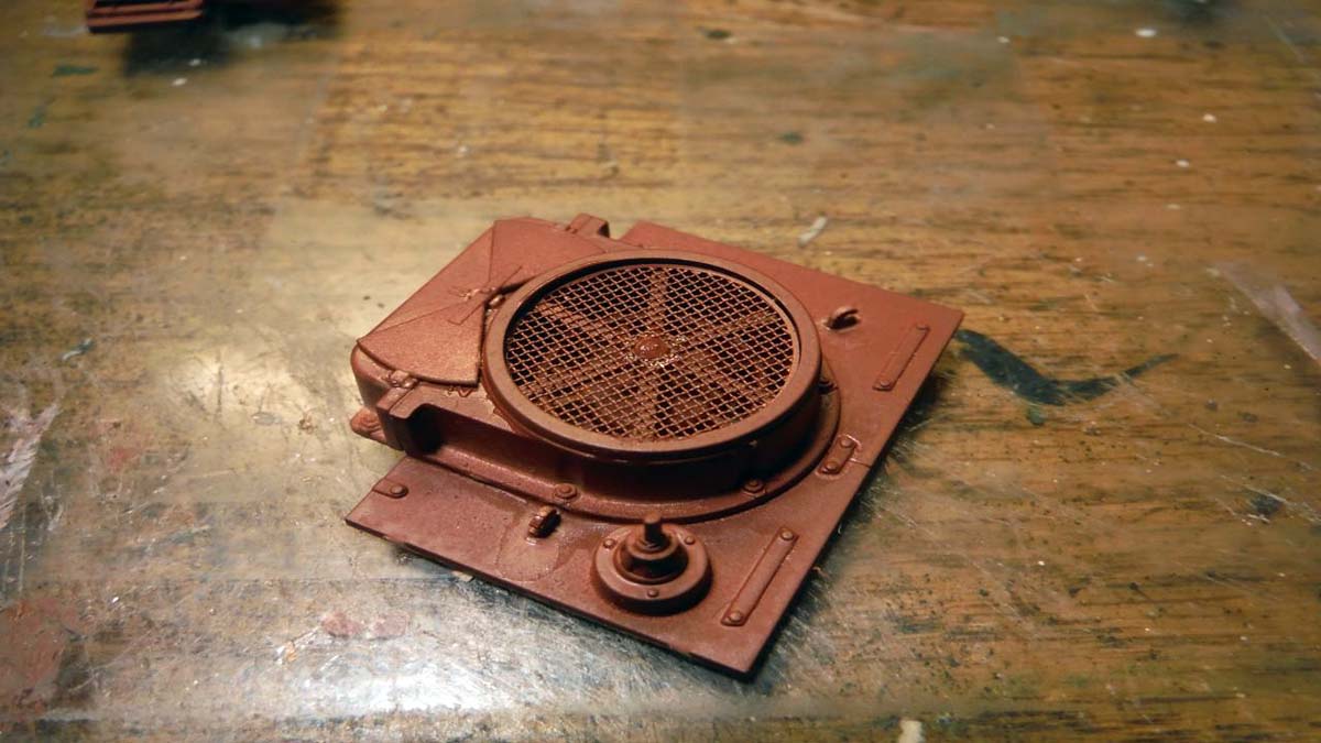
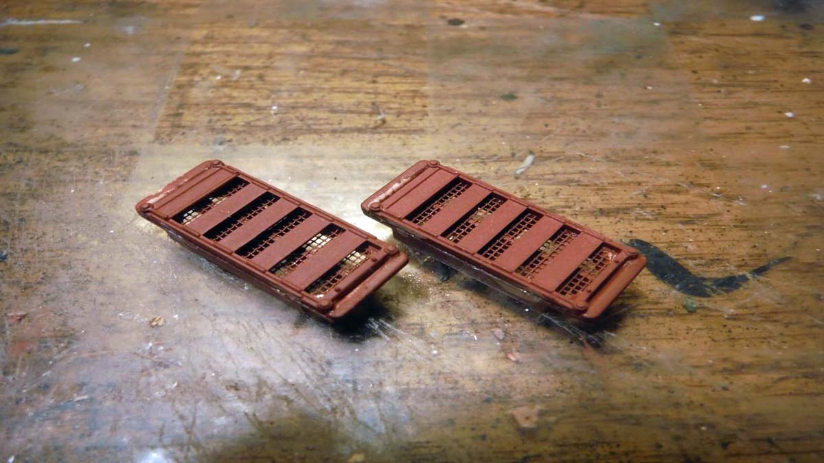
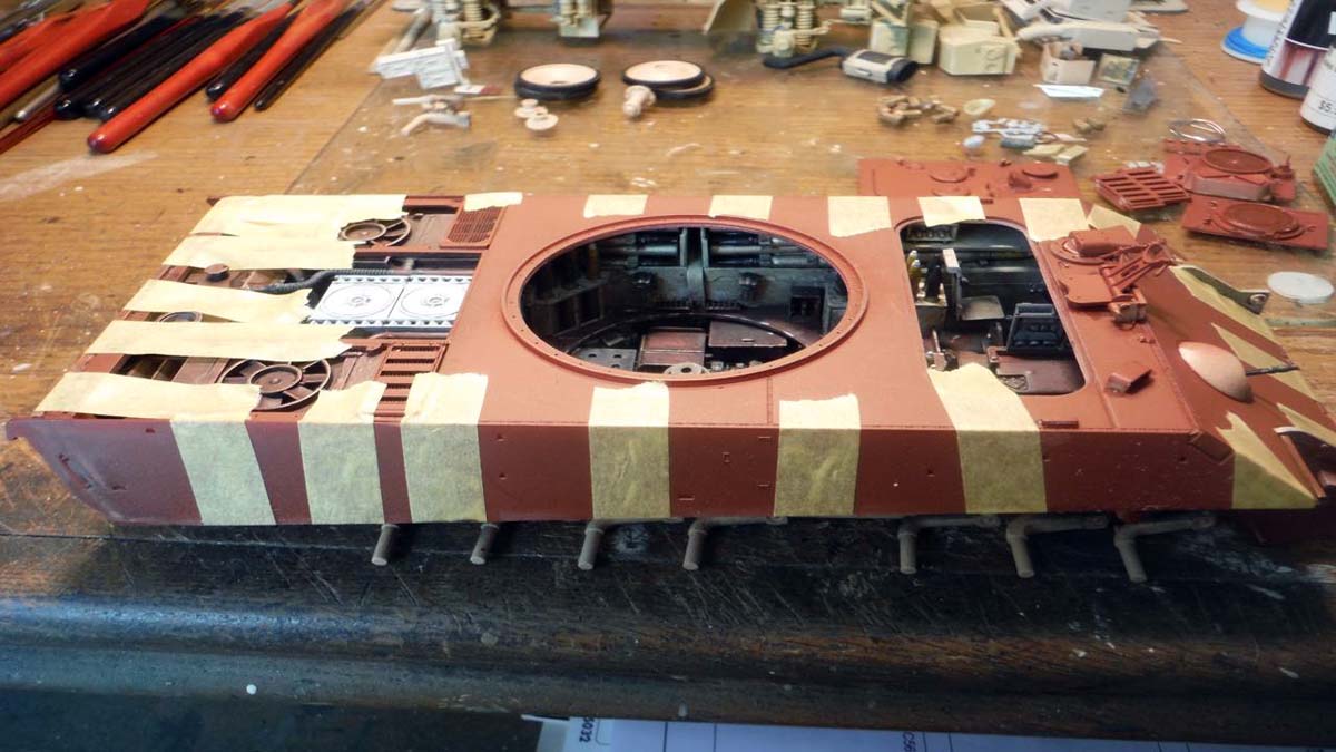
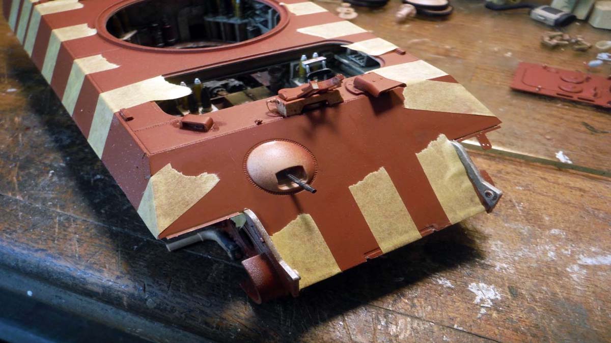
I went on to step 24 and 25 but left the hatches un-glued so that way they can be removed to view the engines. There were a few punch marks to be filled away or filled. I left of parts J11 and Y88 till after I painted the camo pattern. I glued emplaced two completed vents (G45, Y76, and G8) to the front of both radiators. With the rear engine hatches, front drivers and radio hatch, and turret removed, pretty much the whole interior is visible. I completed step 25, sub step C4, C5, and C6 as seen in the instructions. I just left off parts J39, J79, J61, and J40 (all tools) for ease of painting. In step 26, the only thing I did was leave off the track till they were painted and the camo of the hull was painted. In step 27, again the tools, parts J82 and G51 where left off for ease of painting. Hull was painted a 3-color camo pattern and all touch up was done. Then I set the hull aside to work on the turret. Both the turret and hull will be weathered together once the turret is complete.
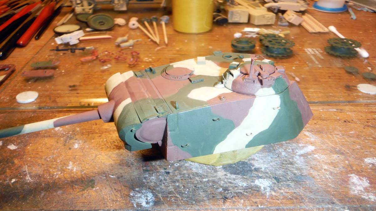
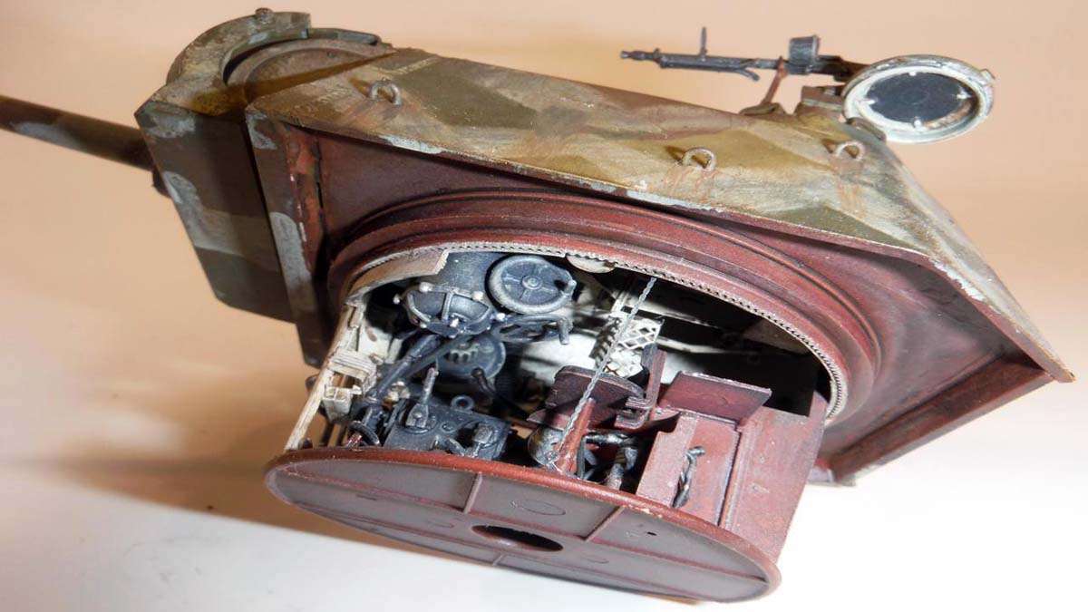
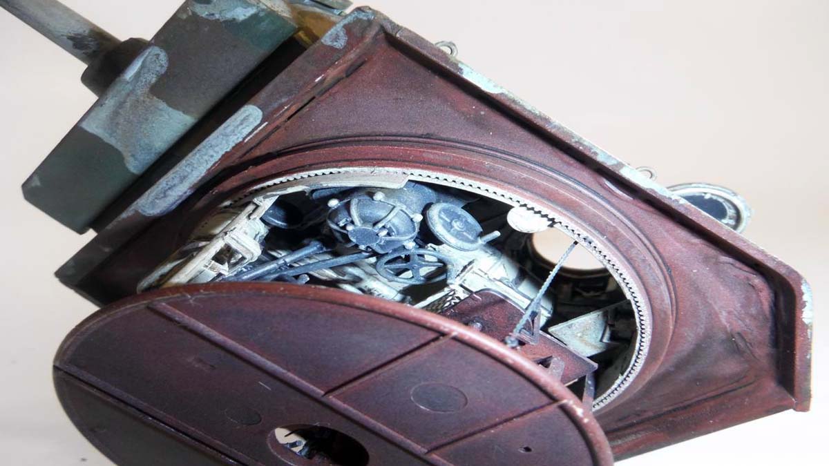
Turret
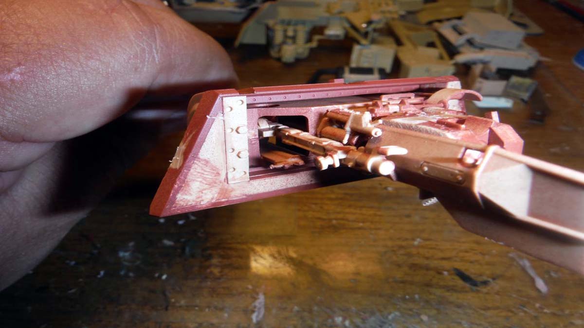
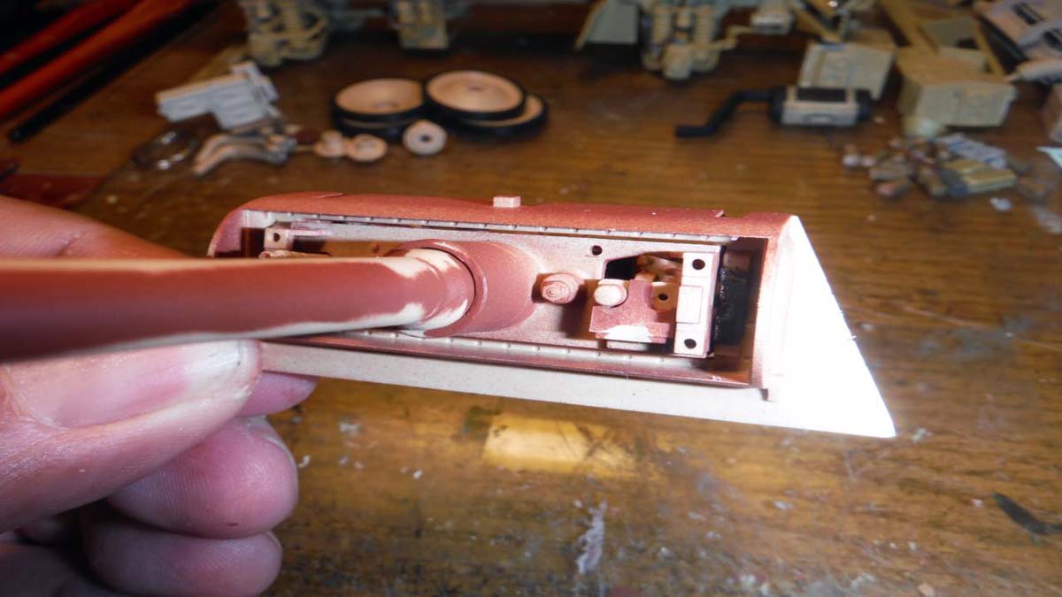
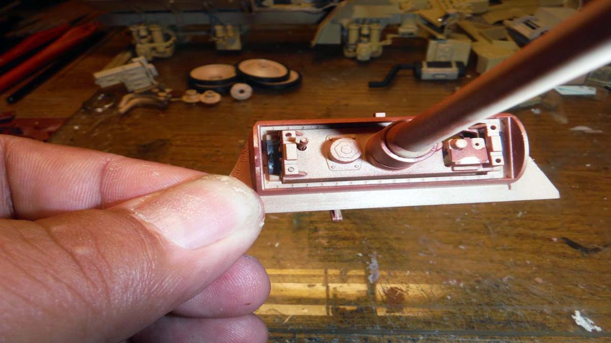
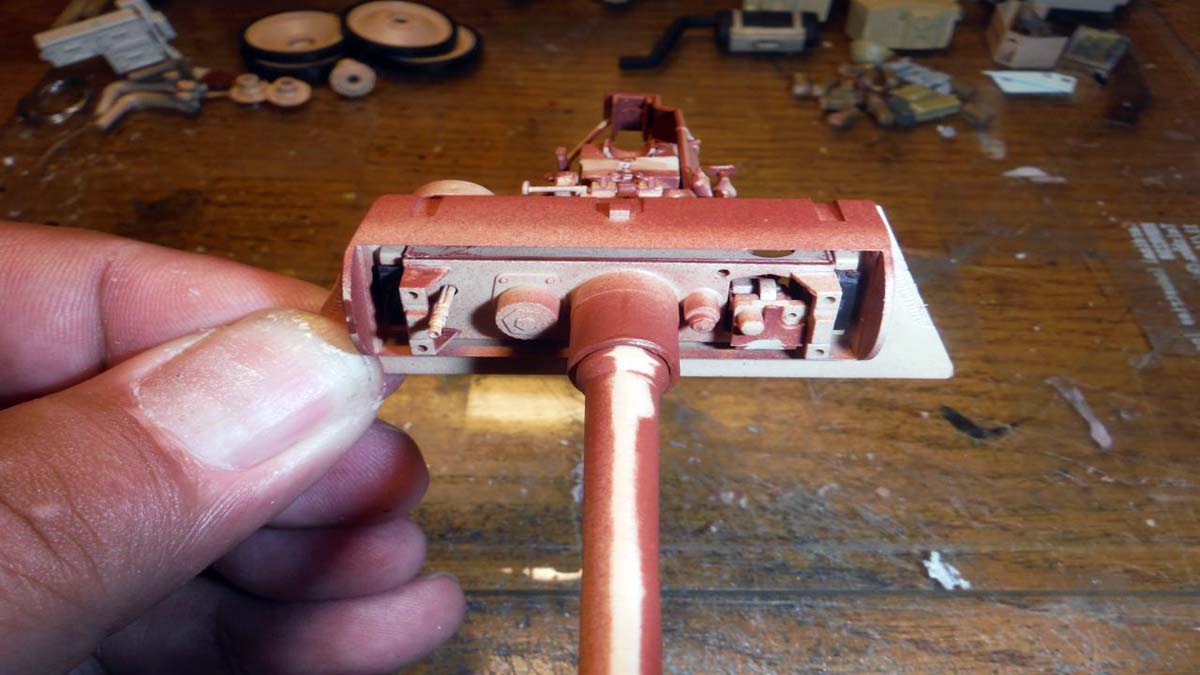
I started off with what turned out to be a pretty difficult piece of photo etch to work with on page 7, sub-step A2. Yes, it was difficult to bend and secure, but with lots, and I MEAN LOTS, of patience, it can be done. I went back and completed all the rest of the steps for the main gun, step 1 through 5 with out and problems. All this will be painted Cremeweis except for the coax gun and sight (A98). Again, be very careful with the little parts and the carpet monster.
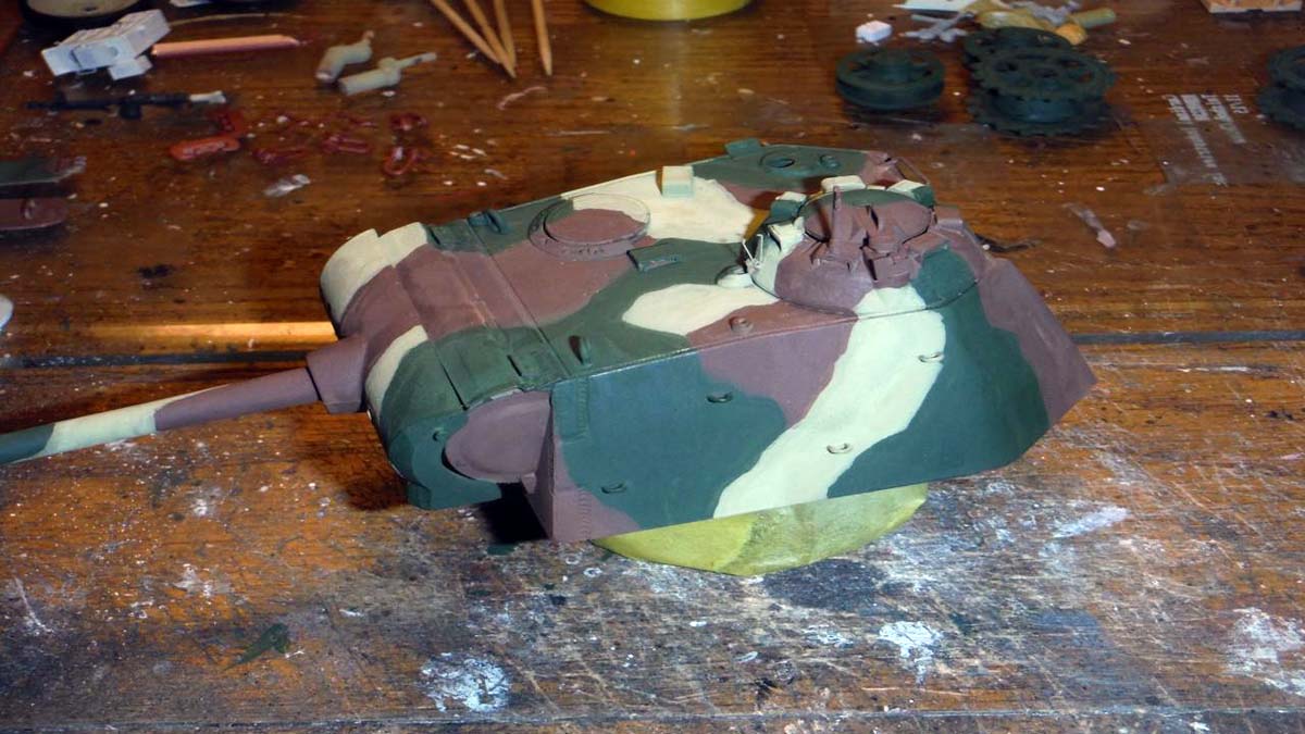
Since I chose not to utilize the clear parts and paint over them, I went ahead and glued everything in sub-step A3 on page 7 without worrying about the clear plastic. There was a very small dimple on top of the clear turret that needed to be filled. On page 8, sub-step A4 and A5, I went ahead and glued in all the clear periscopes without masking them. I left off the machine gun in sub-step A6 for ease of painting and also so it wont break off during handling. I did leave off photo etch parts Y59 till after the periscopes, party A21 and A10 was completed. It was easier and the photo etch didnt break off as easily. There were no issues with step 6 and 7.
In step 8, 9 and page 10 sub-step A7 are very small parts, so be careful when cutting them off the sprue. I wish that RFM would have made part B16 a soft plastic or vinyl piece. In step 21, it did create an issue with me and I will explain when I get to that step. In page 11 sub-step A8, I left off part B51 till step 18/19 so that way it can be aligned properly. I didnt have any more issues till step 12 when you had to bend the metal cable. The measurements were too long in the instructions for that metal cable. Steps 13, 14, 15, and 16 went without any problems. In step 17, you have to attach these two cables from the drive motor in the hull to the turret. How you do so is a mystery to me, so what I did was just cut it right before it is supposed to be attached to the drive motor in the turret and leave it hanging there. When the turret is in place those two hoses look attached and when the turret is out, they are just there naturally. In step 18/19 is where you can attach part B51 from page 11 sub-step A8, to get a better alignment. As I said, I wish that RFM had made B16 and now B14 in step 21 vinyl. In step 21, you have to mate part B14 to B16. If you happen to not glue part B16 wrong, like I did, you will have a gap and will also be off alignment. I had to use super glue to fill in the gap.
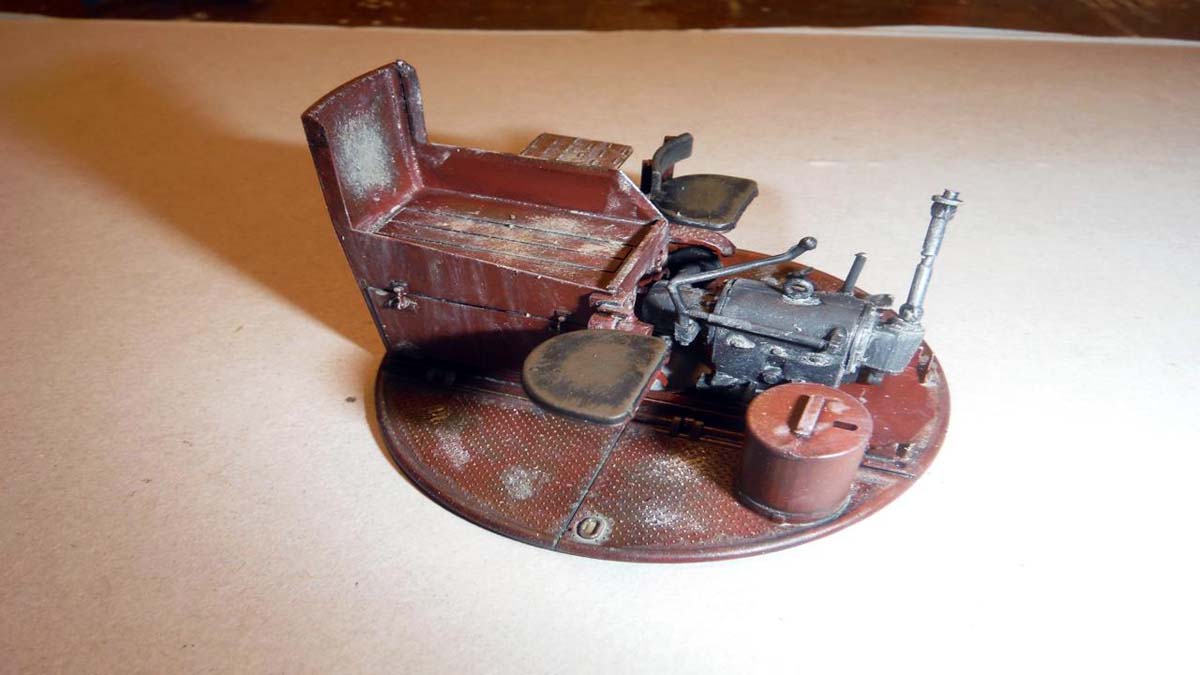
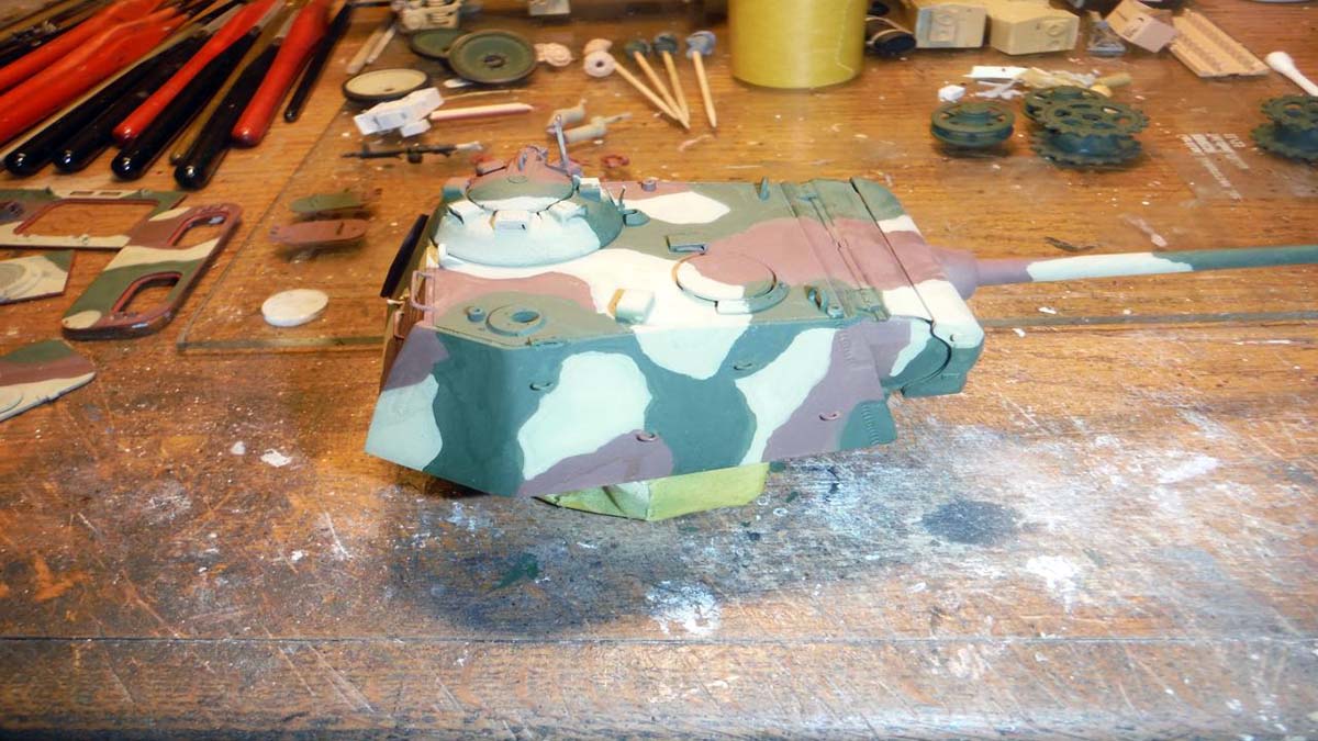
Painting
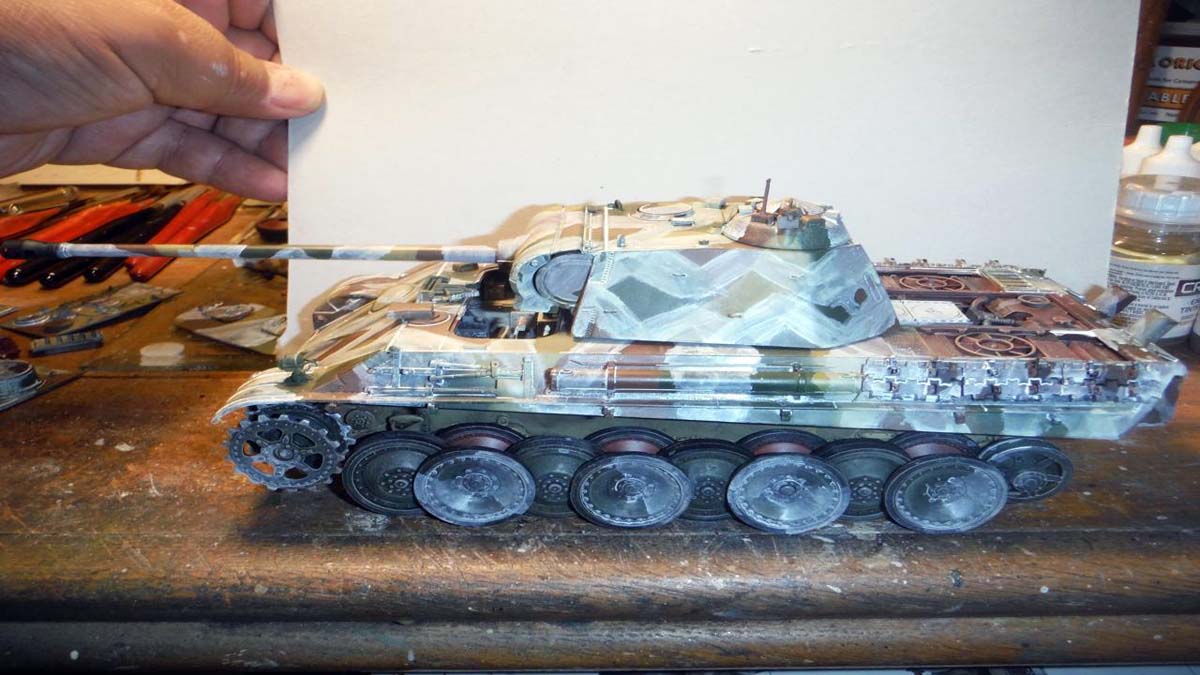
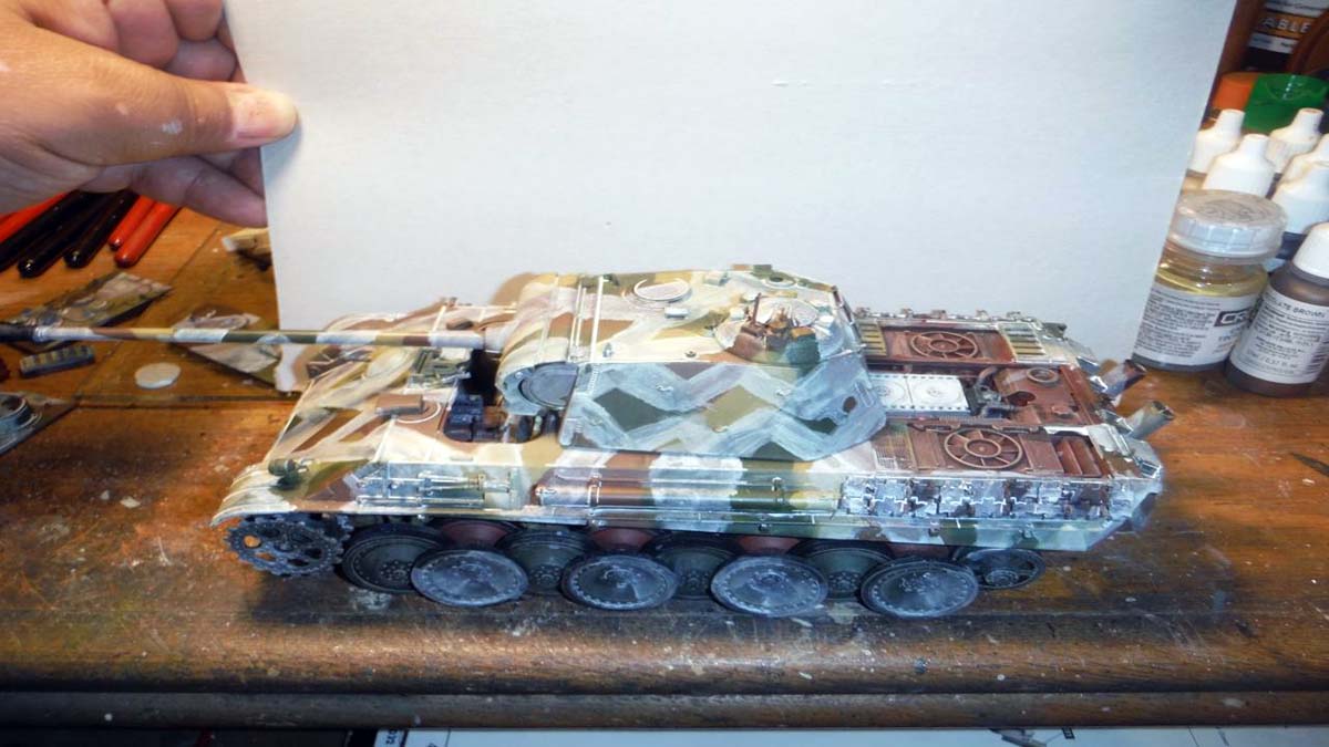
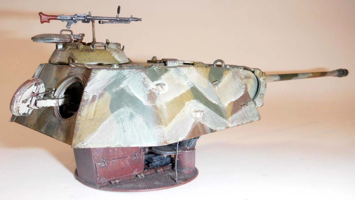
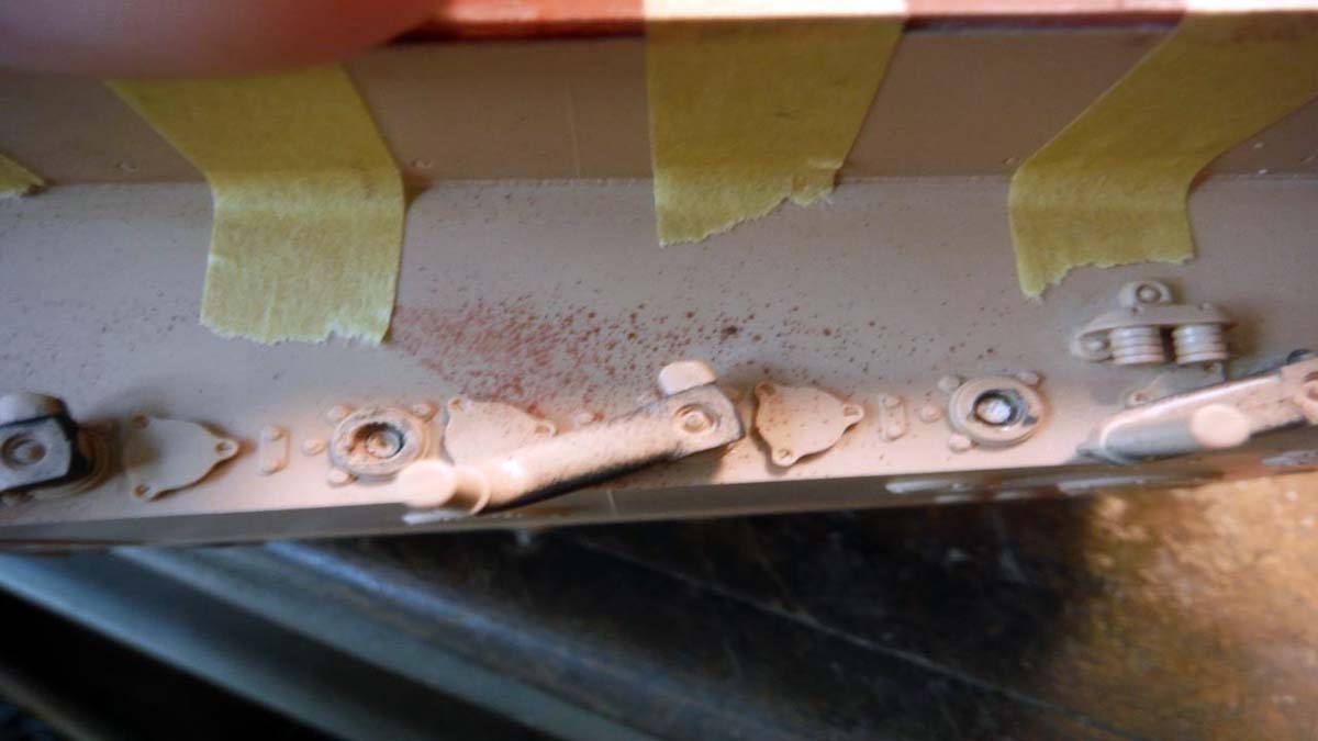
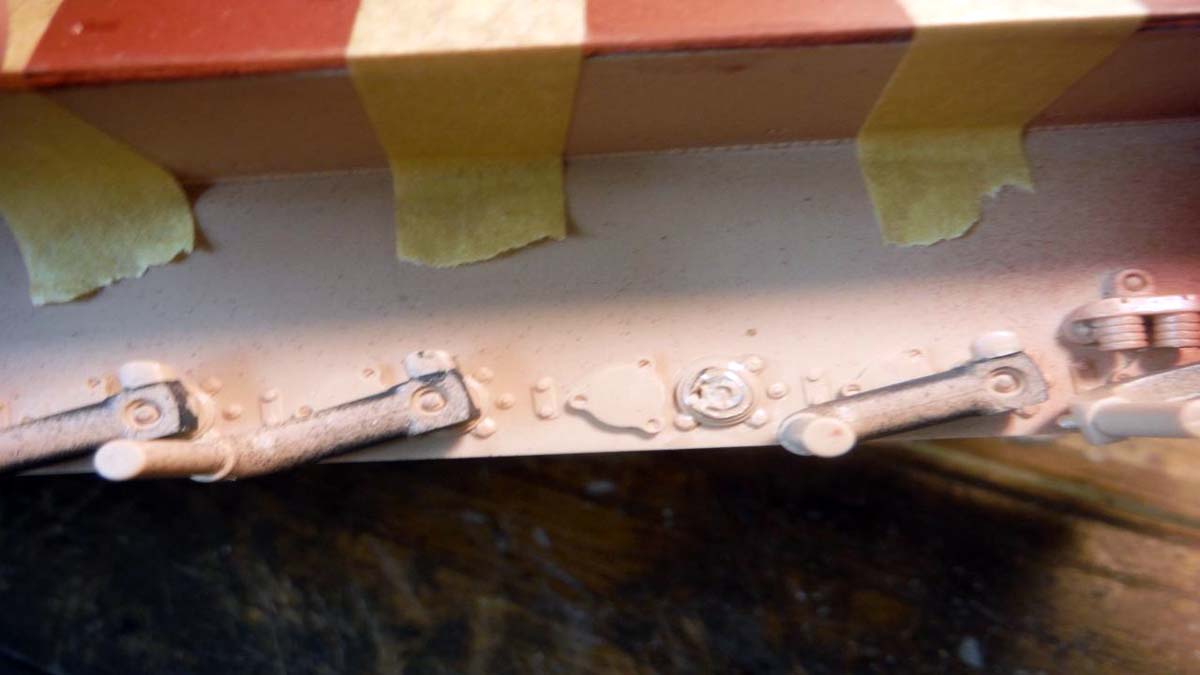
Tamiya paint was used for the main 3 colors of the camo pattern. At Hobby Lobby, I found in the clearance isle, Testors White Wash. I had it in my paint stash for a while and finally decided to use it on this project. Before I attempted to put it on the model, I sprayed the 3 colors on scrap and then painted the white wash with a bush. I was satisfied with it on the scrap, so I went ahead and used on the model. The effect came out pretty good. All the detail painting was done using Vallejo paints and washes and pigments also came from Vallejo.
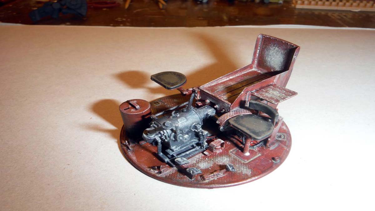
Conclusion
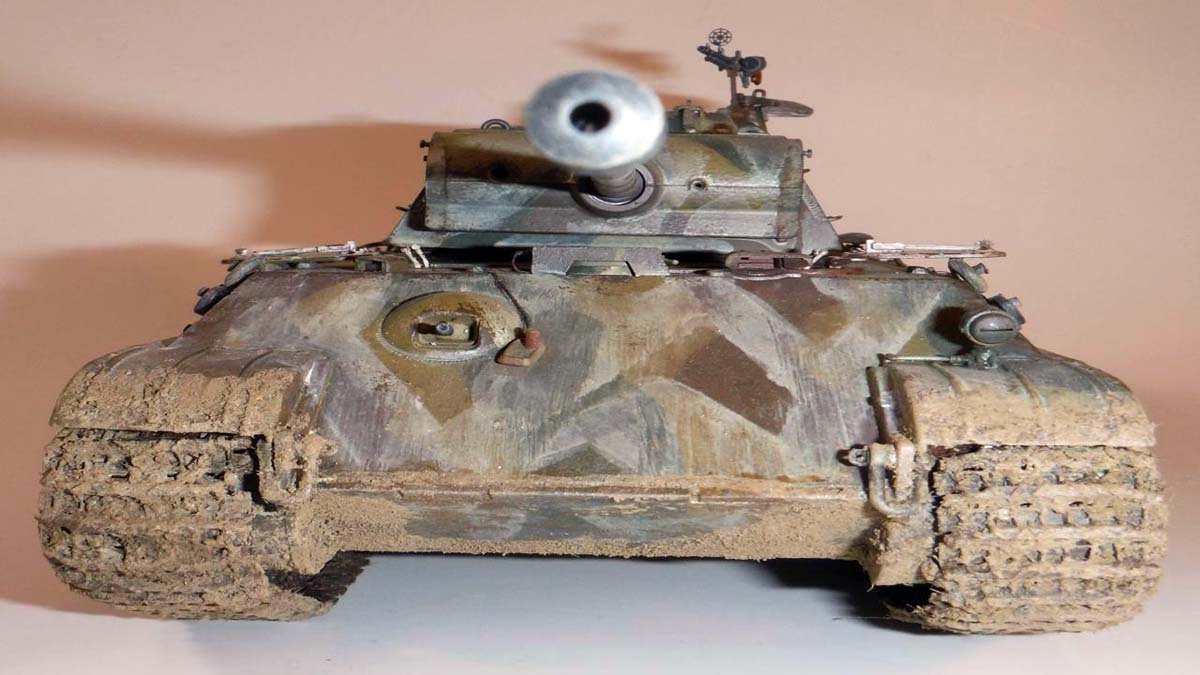
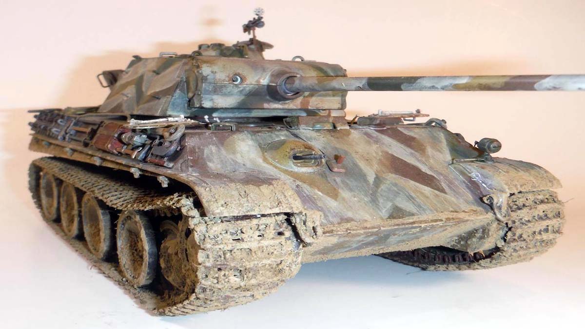
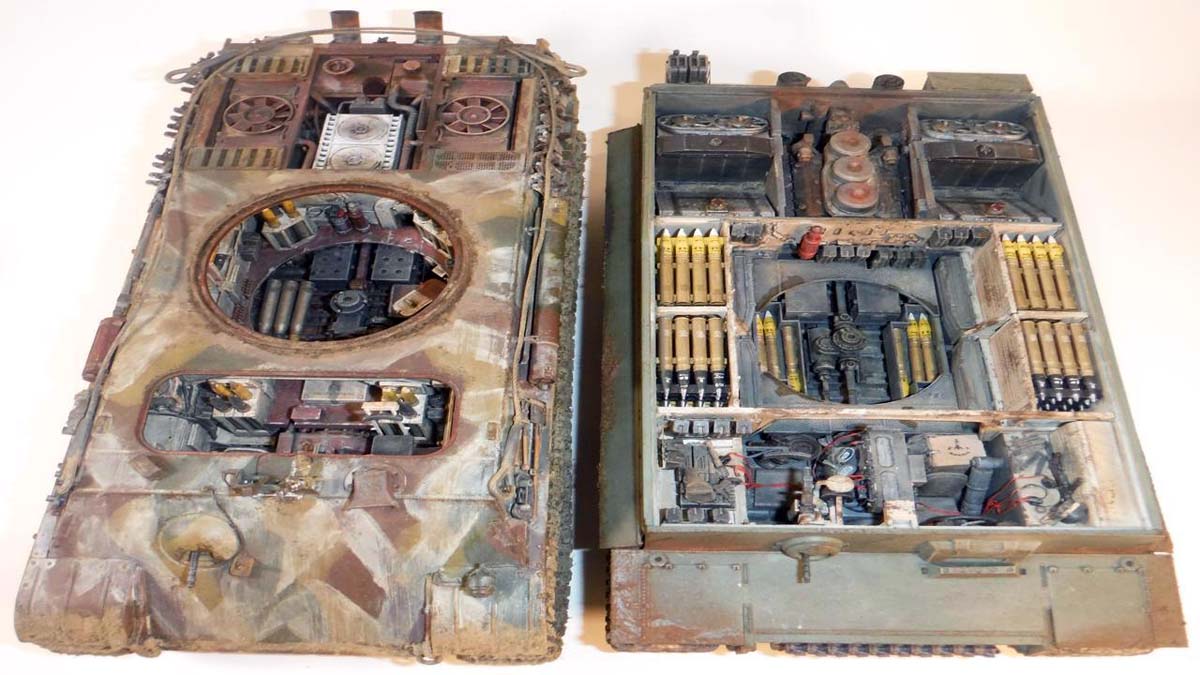
In my opinion, this kit is not one for the beginner. It is a very complex build where you have to really study the directions and have a game plan in place to tackle the baby. Now I dont claim to be a Master Modeler like Christopher Mrosko, Robert Burik, or Pascal Busset whose work is beautiful, but I do have a few kits under my belt and I had trouble with this kit. The photo etch frame in the lower hull and frame around the main gun would prove to be difficult to a beginner and maybe even a moderate builder. The sheer amount of parts would scare anyone away. A lot of time and decision making went into this kit, unlike any other I have built. Would I do it again, hell yes!
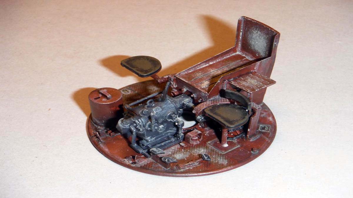
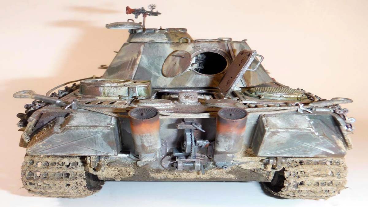
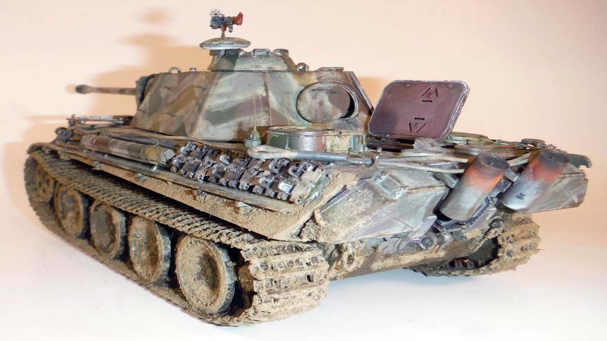
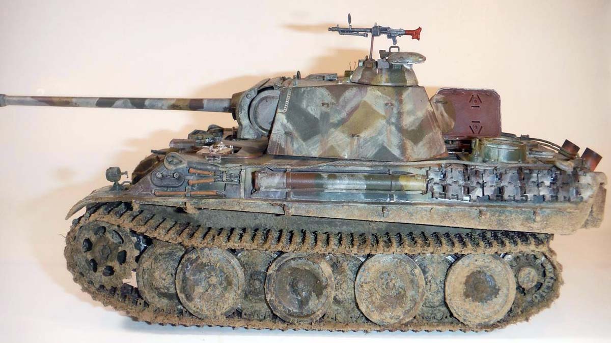
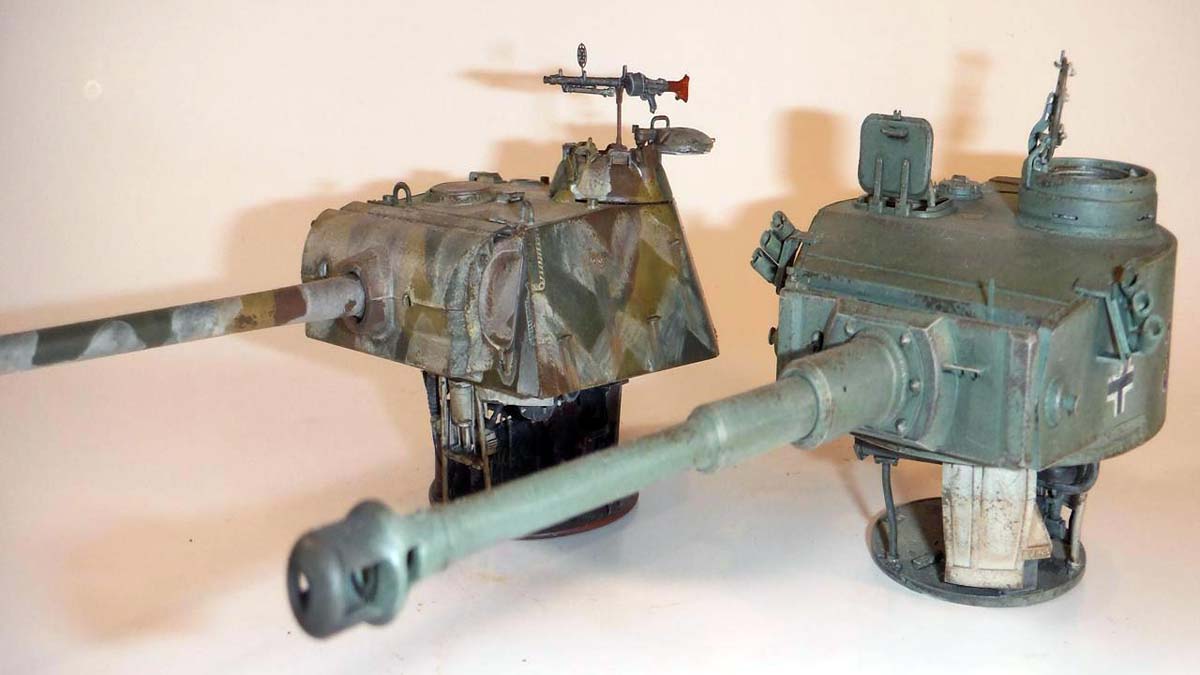
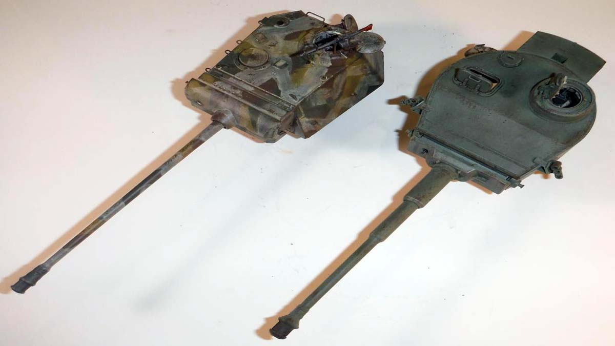
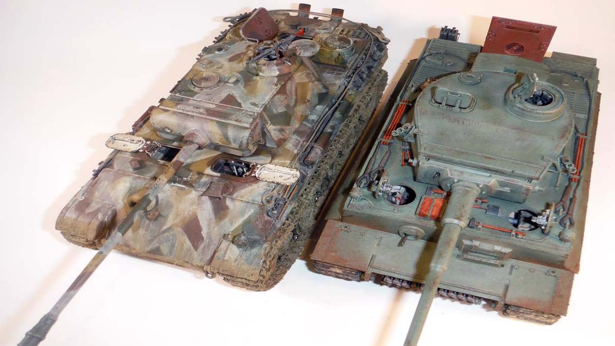
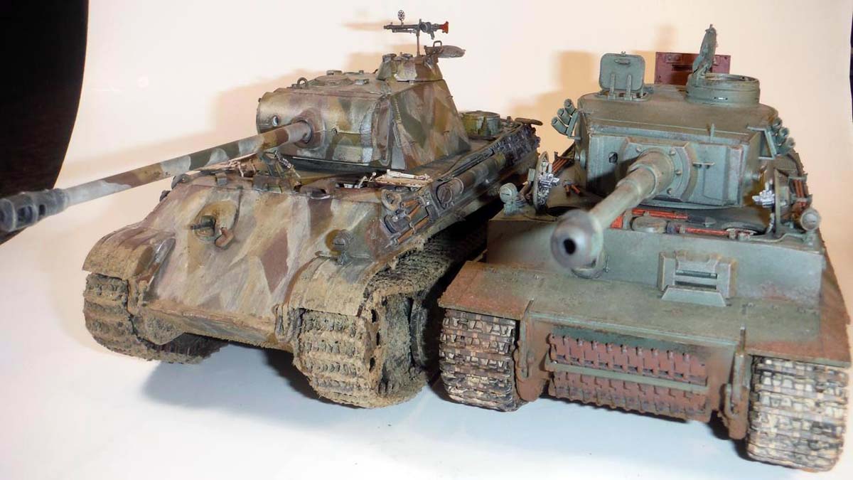
As you can see in the pictures, the Panther Ausf. G looks awesome next to its big brother, the RFM Tiger 1. Another opinion I have is that RFM needs to just stay away from the clear plastic gimmick and just stick with engineering the kit like the Tiger 1 kit and have them engineered with removable tops located along natural lines of the real vehicle. Also start incorporating some more mixed media like vinyl for hoses.
Bottom line, a beautiful kit but for the more experienced modeler.
SUMMARY
Pete Becerra tackles the Panther Ausf. G with Clear Parts from Rye Field Model in 1/35th scale. Pete has provided a full build and finish of the model in this review.
Our Thanks to Rye Field Model! This item was provided by them for the purpose of having it reviewed on this KitMaker Network site. If you would like your kit, book, or product reviewed, please contact us.
About Pete Becerra (Epi) FROM: TEXAS, UNITED STATES
I am 48 years of age. I have been modeling since I was around 8 years old. As you can see from my signature, I am retired from the US Army and Texas Army National Guard. I served 6 years in active duty from 1989 to 1995 and in 1998 I joined the Texas Army National Guard and been serving up unt...
Pete,
Fantastic build review. I've been waiting to read your comments before getting started on my build. Your end product looks amazing.
I will be adding your suggestions to my own notes as I try to figure out how to tackle this beast. One item to note is that if you use the steel roadwheel, in Step 31, there are two positions for the torsion bar. It needs to be glued in the lowest position so that you don't get that gap with the tracks. It should not be lined up with the other torsion bars as they dry. Just need to finish whats on my table before starting this one.
Great build review! One thing that slipped away, is some distorted pictures, especially top shot of panther + tiger.
I would also like to add about instructions. Everybody says it is important to study them, before cutting the sprues. While this is true, it is hard not to lose focus with 70+ steps. Similar story with errata, or suggested fixes to the model. While it is very good to have such information complied in review, its still too much information to remember when you start building your own. And fallowing instruction manual, plus 5 reviews or blogs while building the kit is plain overkill.
The answer to this would be marking out the instructions. Placing notes on the steps, what to do and what not, putting down shortcuts to the other steps, if some part is to be attached in earlier steps and so on. I will try to do this on my next build review, so modelers can print out revisited instructions, and build according to this, single source. You can also mark out what options/tools etc are correct/wrong for given version.
Darius, That is exactly what I am doing with this kit. I have scanned and printed every page and I am making notes for every step and sub-step. This is a complex kit and the only way to keep from losing control is lots of pre-planning. I have easily spent more than 10 hours studying the instructions and making notes. The fruit of that labor ended up being the in-box review that was posted a few weeks back. Now, I will incorporate Peter's build experience into my notes. Once I pull the kit off the shelf to build, I'll spend several more hours studying the steps and my notes before I remove the first sprue from the box.
Mark, that's what i usually do with most kits too. What i would love to do, is to print "revisited" instructions done by somebody else, who has already done it for review. Don't get me wrong, i love doing research work (there's lots of scientific work in my job), but i prefer studying history of exact vehicle I'm building, rather than instructions. Yes, you have to understand what you will be doing in next step, but there is no point to understand where you will put some microscopic part 50 steps later. That's engineers, who is doing instructions work. That's what makes the difference between good and great kit. If Takom panther i reviewed recently had instructions like Tamiya, it would be perfect kit for me. And now, kit is very good, but probably 20% of time to build it will be spent on instructions.
So scanned instructions with well laid out comments are worth the gold for me. And it doesn't really take so much more time for reviewer to do this. And it it much more informative than hundreds of pictures taken.
Really an impressive build and I'll be looking on as I build mine but I only had one question: as you had the transparent hull version why didn't you leave any areas open to reveal the insides? I'm not too thrilled personally with taking my kits apart to show the interiors so I was just wondering...?
I apologize about the pictures guys. The resize program that I used did something to the pictures. I had moved laptops and down loaded the same exact resize program, but I guess a setting or something was not right. Darren pointed it out to me and it is all fixed no, but unfortunately I don't have the originals anymore.
Frank, as you can see in the below pictures by Voyager Models, with all the stuff added to the sides, it is kind of hard to see inside. This is why I chose to paint the clear parts. Plus i was afraid to mess up the clear plastic with glue and also by removing stuff that needed to be removed in the version I built.
Good enough reason. Then there's people like me who, in the absence of clear parts, pull out our Dremels and cut the tank open to show off the interiors. I think that I'll try hard to use the transparent parts where possible. Rye Field Models recently announced a new interior set for their Panthers that didn't come with one and -apparently- includes openings in the hull and turret to see the stuff. Cool.


Comments